UG Series SIMO Linear Motion
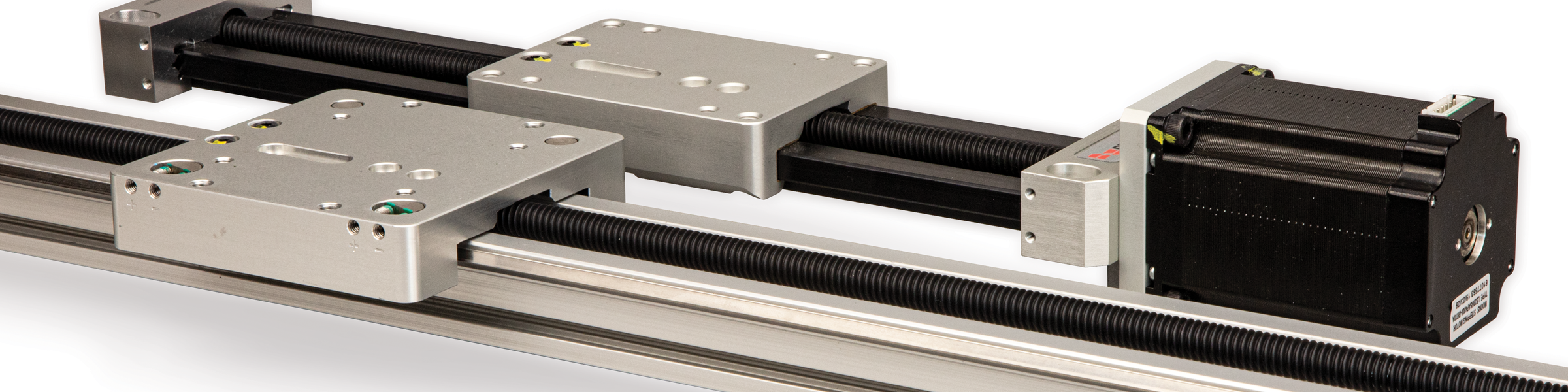
Simultaneous Integral Milling
Operation
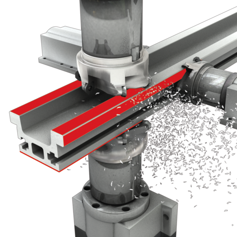
PBC Linear has revolutionized traditional machining with the patented SIMO® (Simultaneous Integral Milling Operation). The SIMO process uses synchronized cutters, eliminating built-in extrusion variances by machining all critical edges concurrently in one pass. This ensures tight tolerances, limited variance and a remarkably straight and repeatable surface at negligible additional cost!
Patented Machining Process
Machined Precision at Extrusion Prices
- Rigid, accurate, repeatable
- Machined rail edges can be used as a reference when mounting
- Low cost
Synchronized Cutters
Eliminate Built-In
Extrusion Variances
| Standard Aluminum Extrusion | SIMO | ||
|---|---|---|---|
| Straightness (Camber) | 0.0125 in/ft (1 mm/m) | ⟹ 6 TIMES BETTER ⟹ | ± 0.002 in/ft (0.166 mm/m) |
| Twist | 1/2° per ft (1.5° per m) | ⟹ 2 TIMES BETTER ⟹ | < 1/4° per ft (0.82° per m) |
| Flatness | 0.004 in (10 mm) | ⟹ 2 TIMES BETTER ⟹ | 0.002 in (0.0508 mm) |


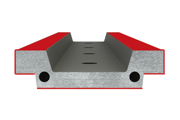
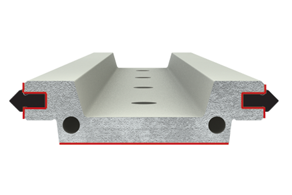
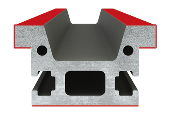
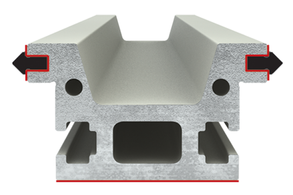
All Critical Surfaces Qualified
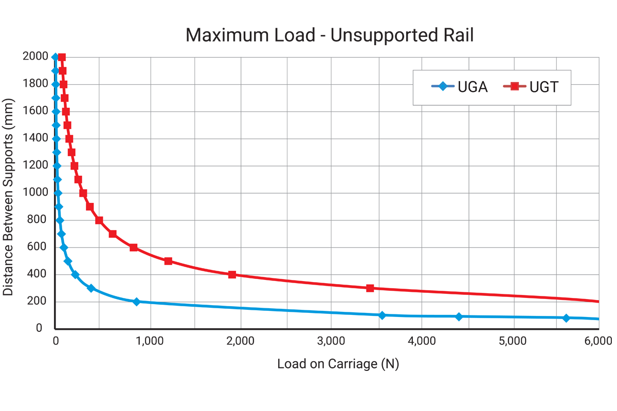
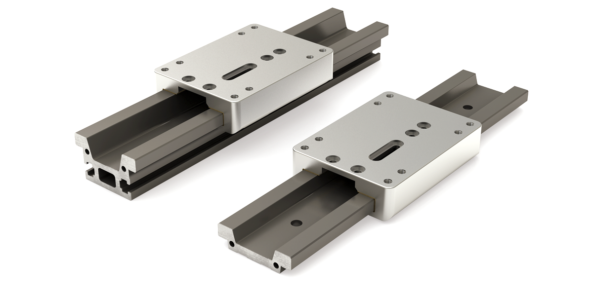
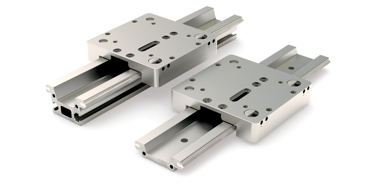
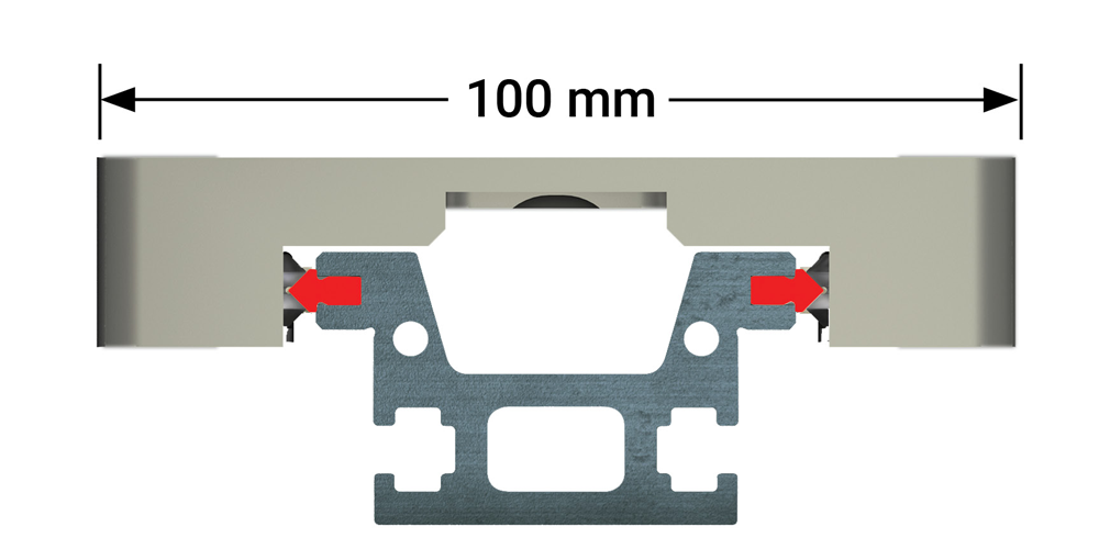
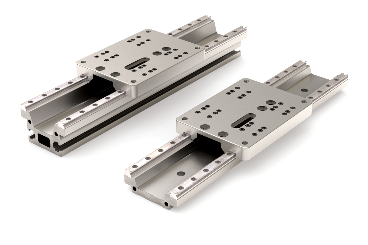
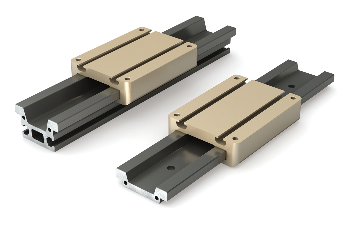
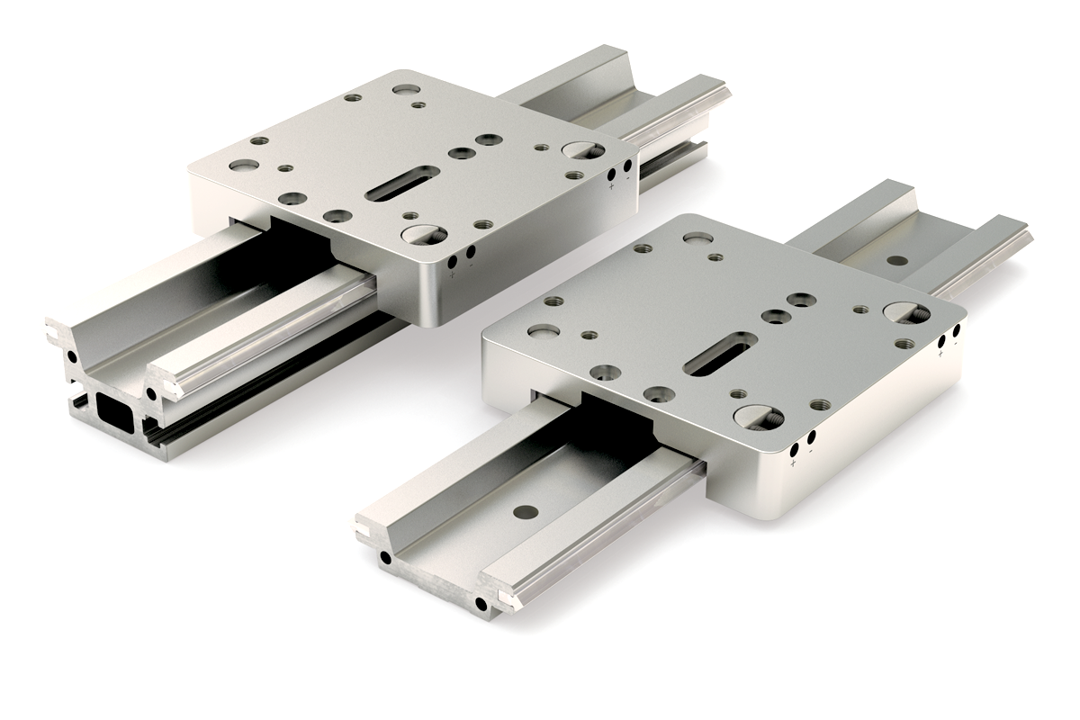
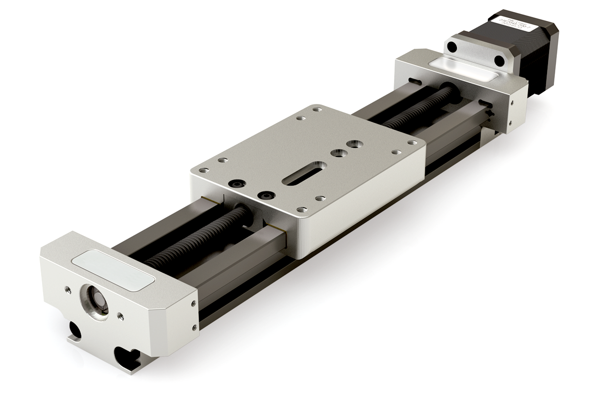
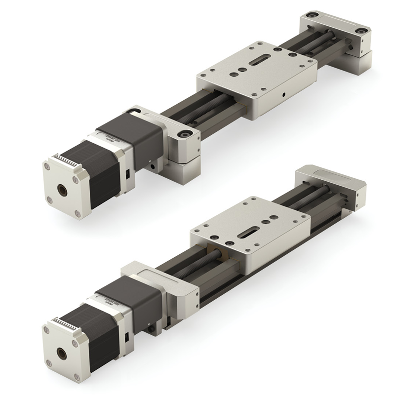
UG Series Linear Motion Platform
Bearing System Options
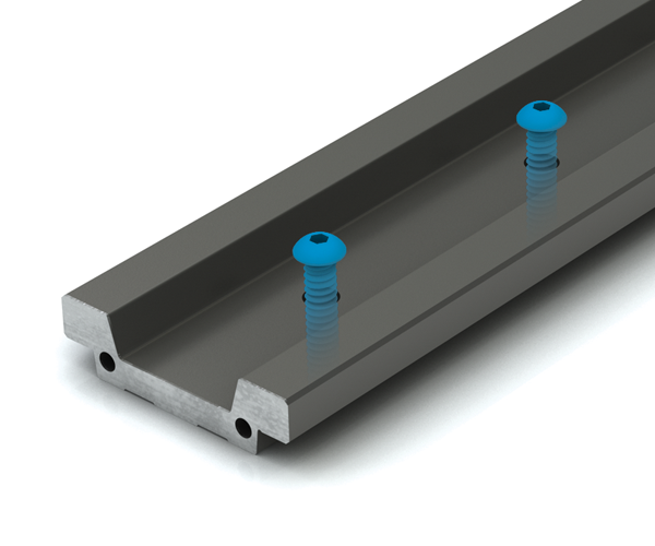
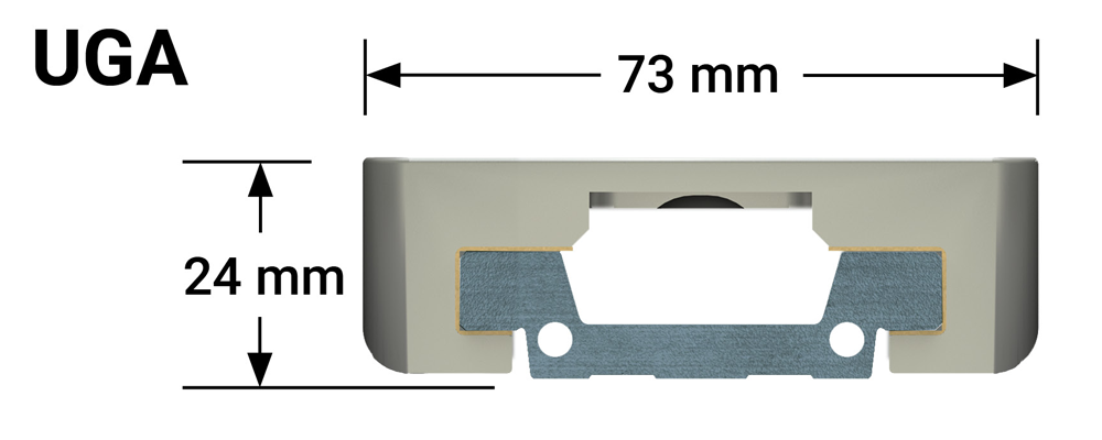
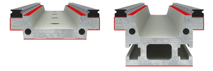
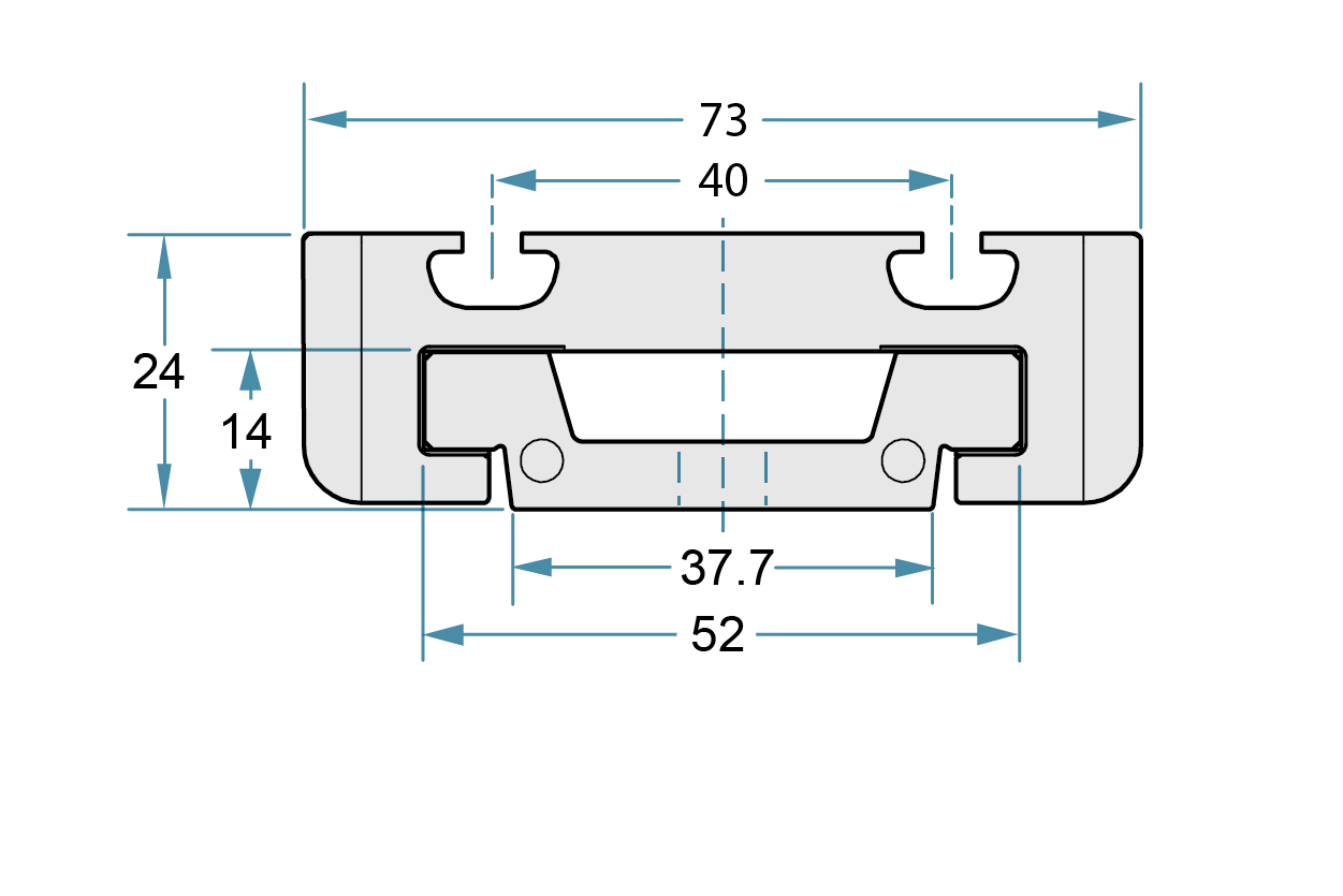
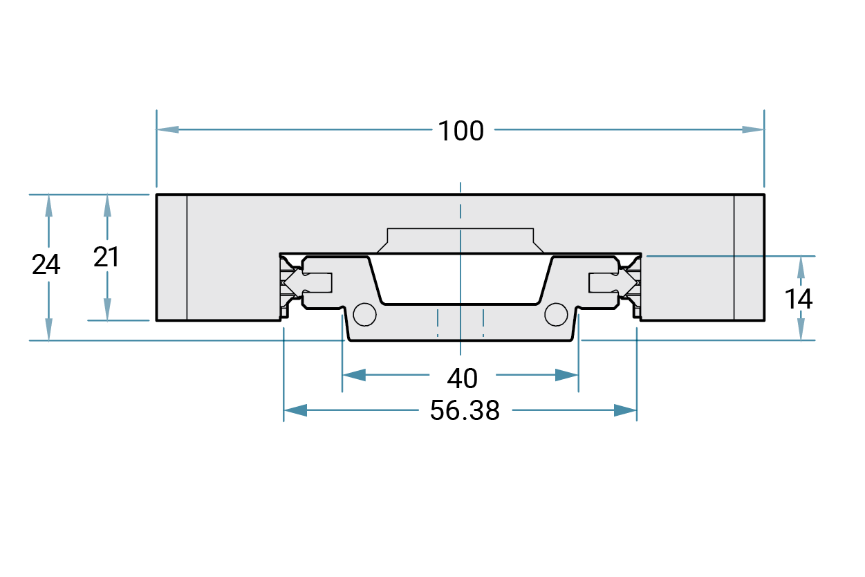
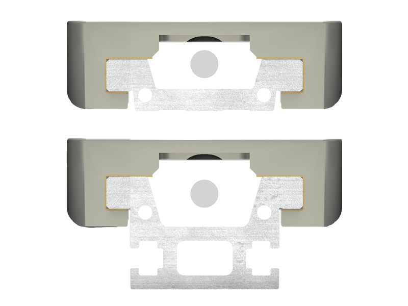
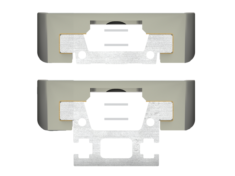
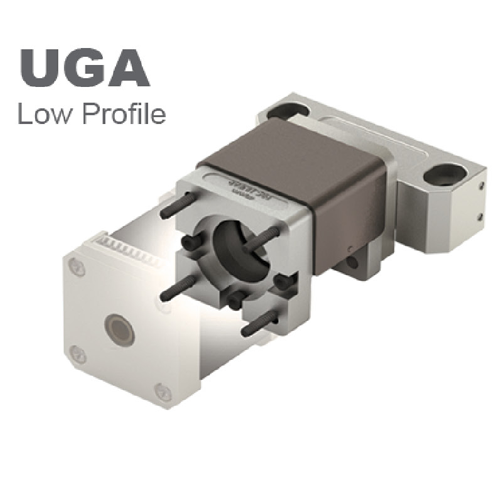
UGA – Low Profile Rail
- Surface mounted
- Ideal for small geometrics
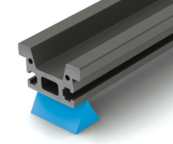
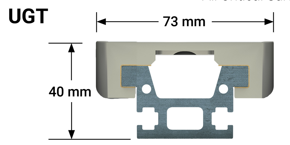
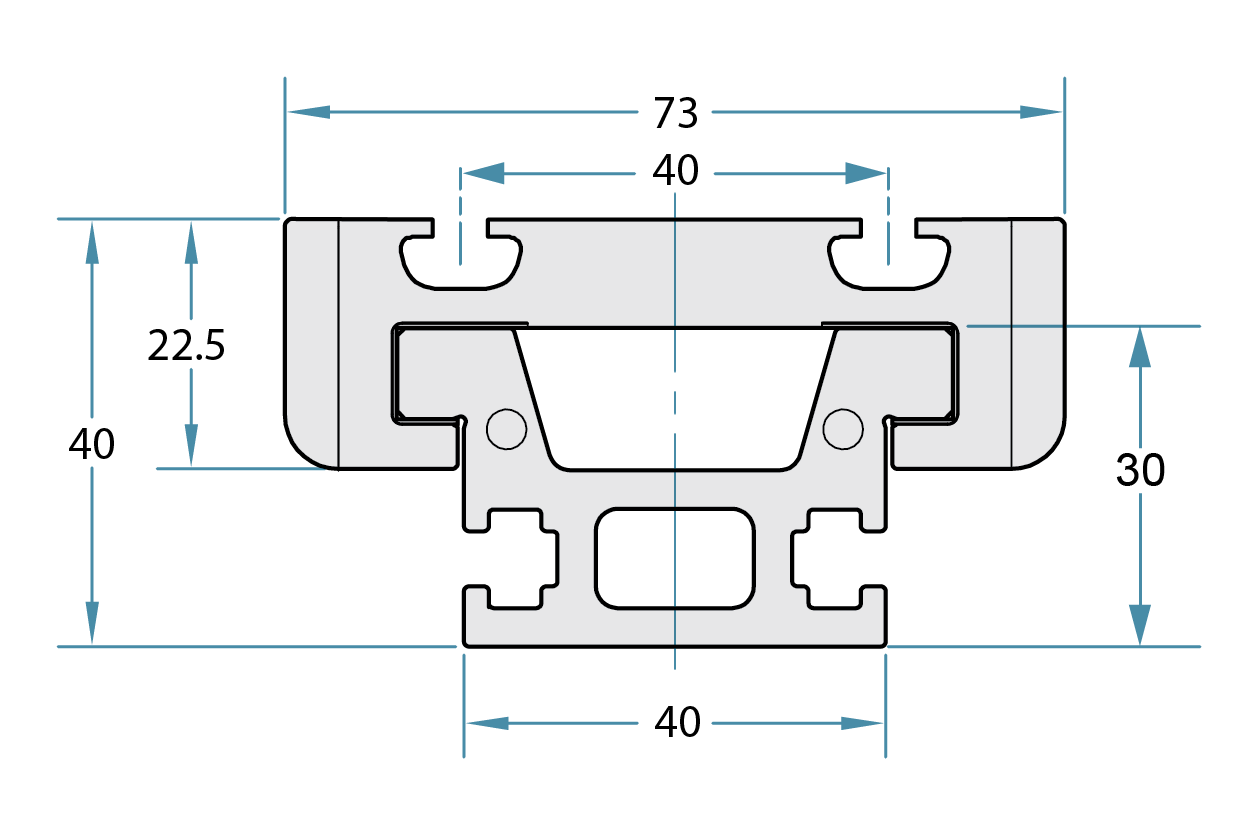
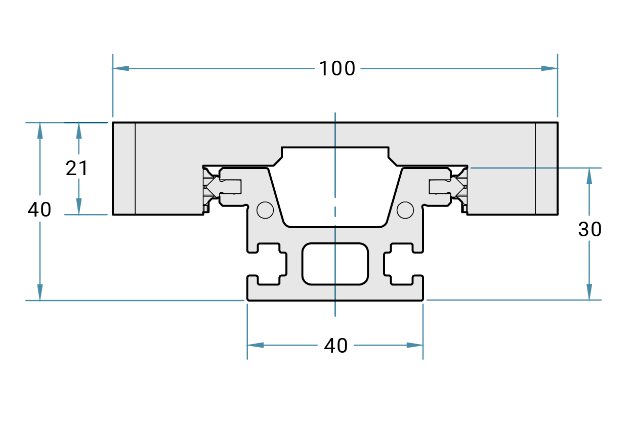
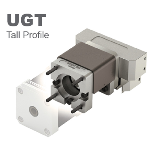
UGT – Tall Rail
- Can be end supported
- Rigid structural component
- T-Slots for mounting clamps and other accessories
Gliding Surface Technology Plain Bearing
(with FrelonGold)
- LOW COST
- Excels in environments from contamination to clean rooms
- Self-lubricating and maintenance free
- Vibration damping
- Suitable for extremely short stroke

Cam Roller Technology V-Guide Roller Bearings
- HIGH SPEED
- Increased cantilevered loads
- Stainless steel raceways resist corrosion
- Sealed V-wheel bearings handle contamination

NOTE: Profile rail bearing & rail with ball screw option
Drive System Options
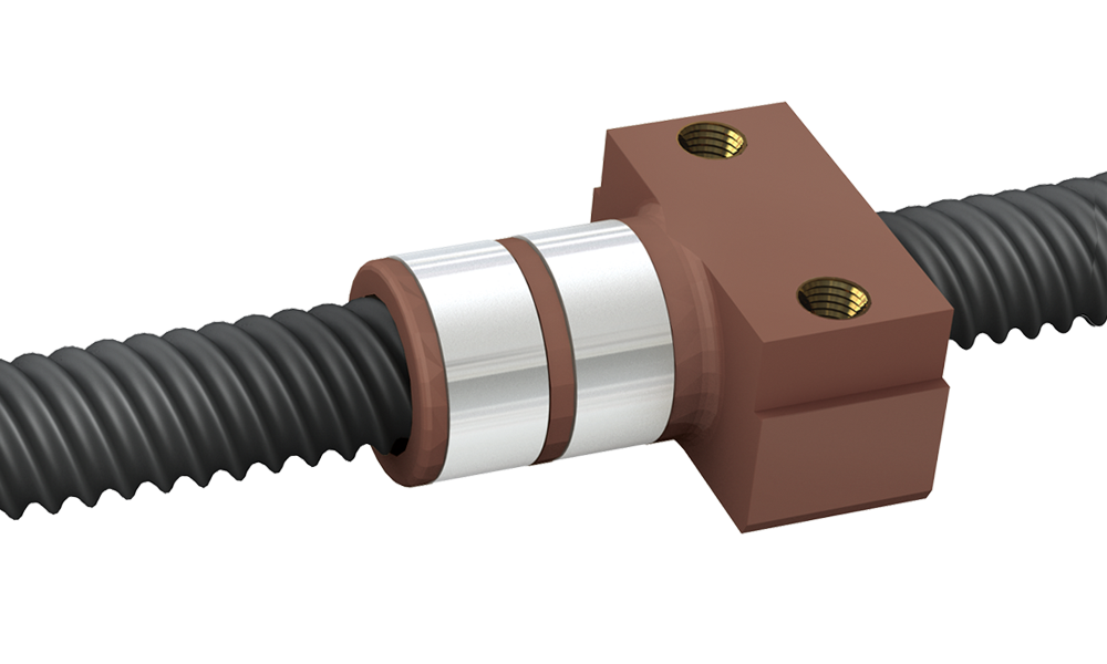
Lead Screw – Low Cost
- Standard fixed or Constant Force anti-backlash nut
- Good rigidity and vibration dampening
- Self-lubricating and maintenance free
Cam Roller Technology V-Guide Roller Bearings
- Good for long stroke applications
- Tolerates contaminated environments

Motor System Options
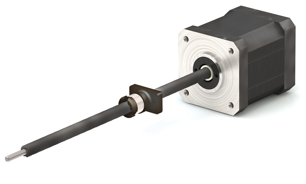
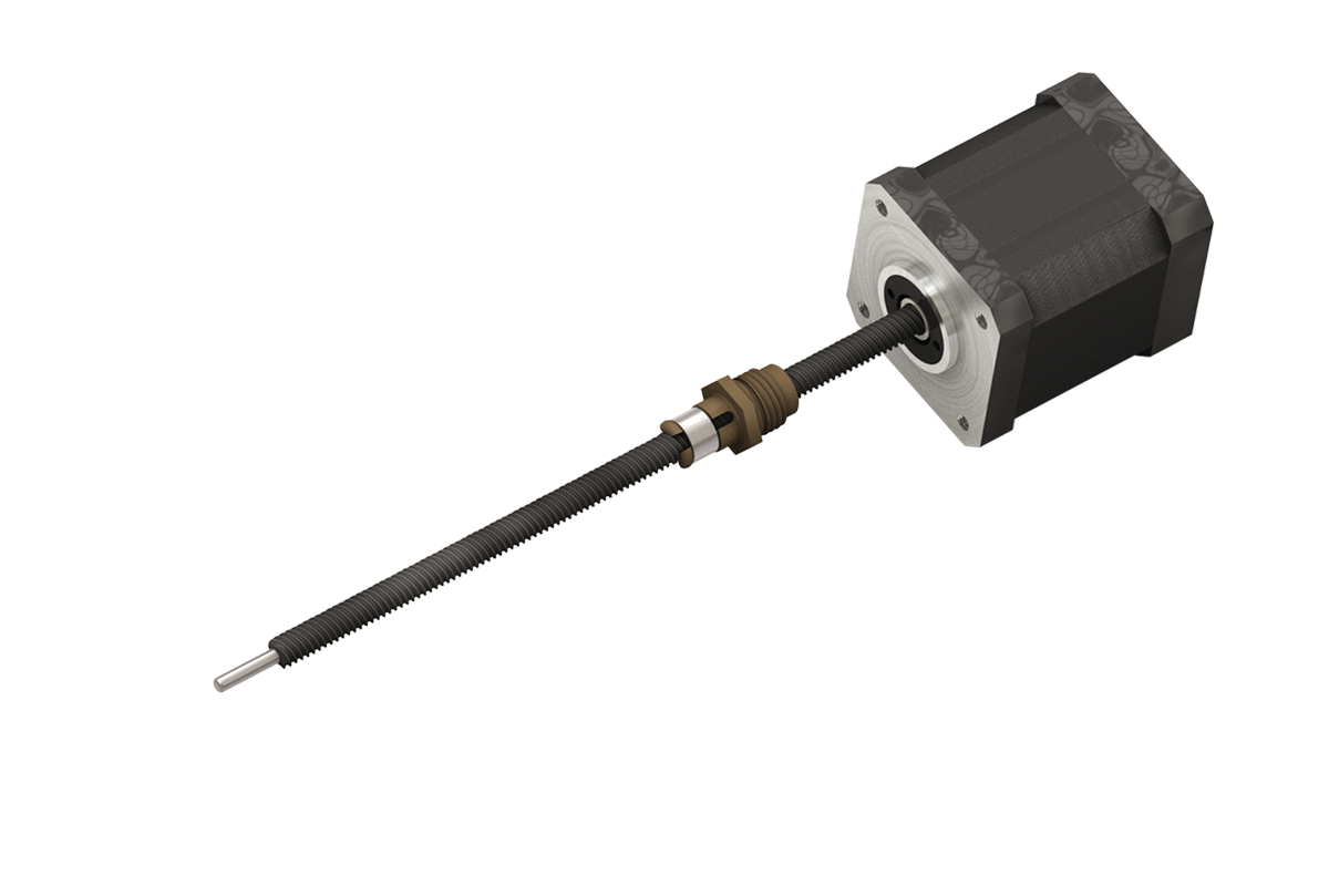
Integrated Screw and Motor
- Lead screw aligned and fixed directly with motor
- Less components means greater accuracy, increased rigidity, and less cost
- Motor is not field replaceable
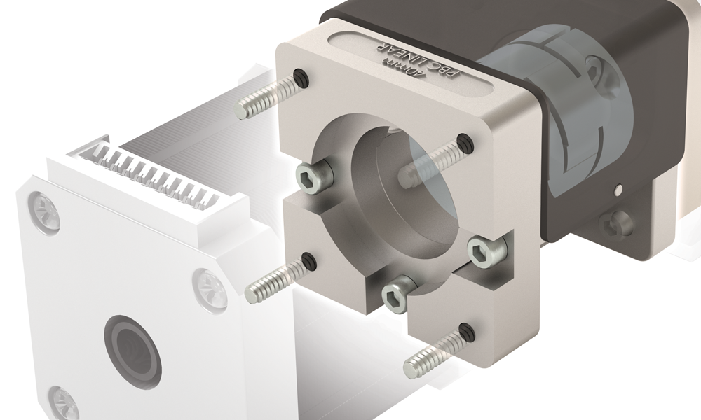
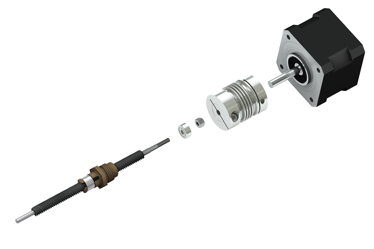
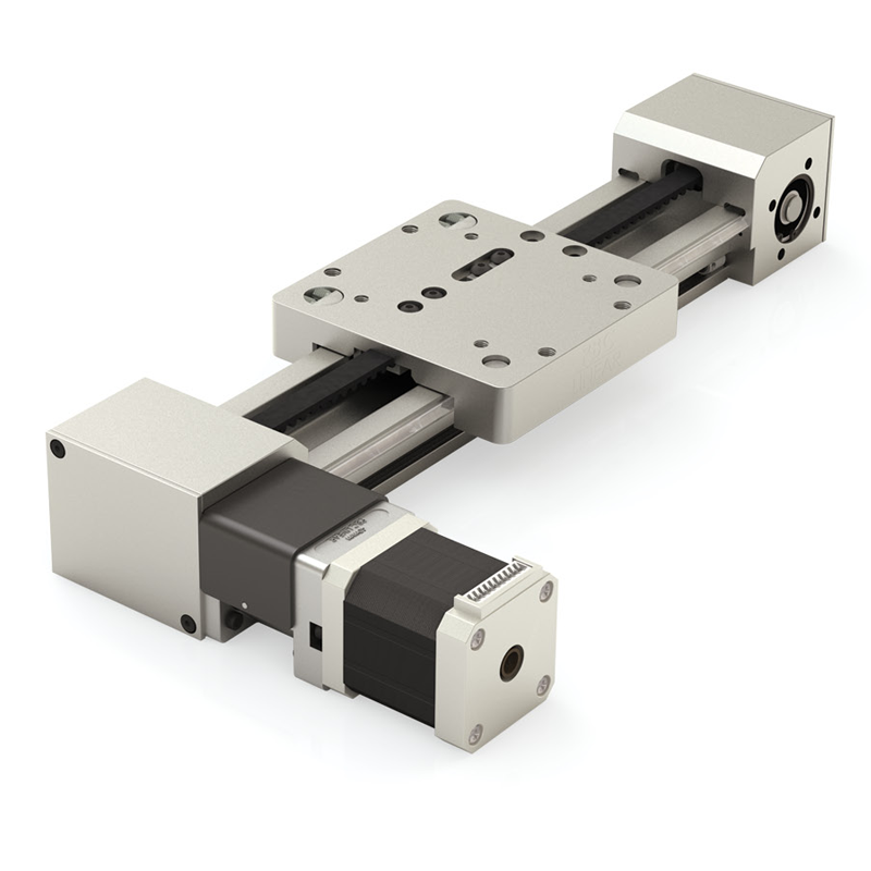
Motor Mount
- Drive the SIMO Series with a stepper, servo, or smart motor, etc.
- One-piece main frame holds shaft-to-shaft centerline
- Allows for field replacement of motor
Applications
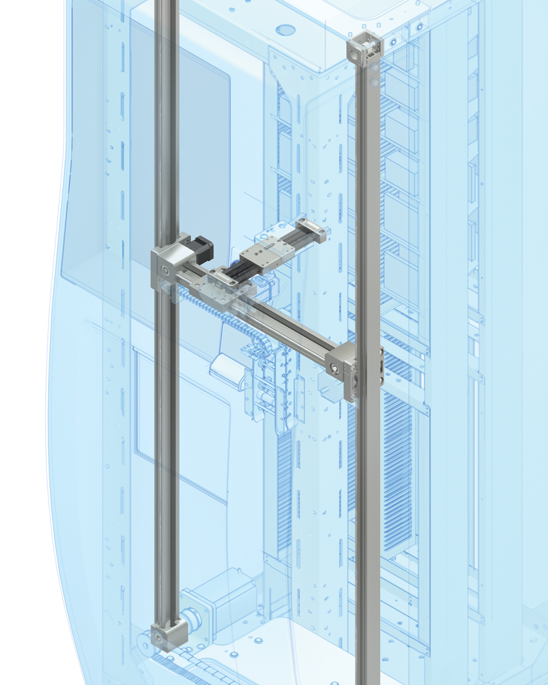
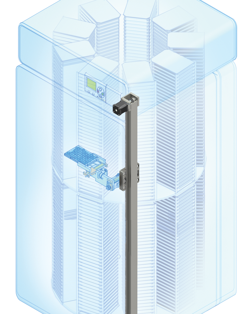
Kiosk and Automated Retail
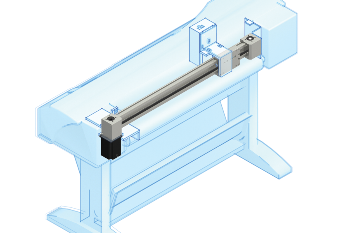
The SIMO Series tall rail (UGT) works well as a structural support – shown here in the X and Y axes in an automated dispensing application. The low profile (UGA) SIMO Series – shown in the Z axis – is ideal for fitting into tight spaces.
- The tall rail (UGT) can be used as a structural support.
- The low profile rail (UGA) fits into small spaces.
Cartesian robotics
SIMO Series' single- and multi-axis solutions provide the accuracy and consistency that pick and place applications require.
- V-Guide bearings provide high speed performance and quick change of direction capabilities
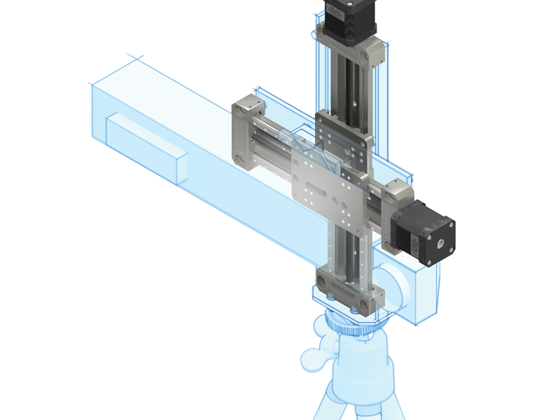
Polar Robot
The SIMO Series can be used in vertically or horizontally oriented applications. The polar robot shown here provides repeatable motion and high accuracy.
V-Guide bearings provide smooth travel and the tall rail (UGT) provides structural support
Scanning Equipment
High precision and smooth operation are required when designing linear motion for laboratory scanning equipment. The plain bearing system utilizes FrelonGOLD® – a self-lubricating, maintenance free surface
Lead screws utilize an engineered high strength polymer, plain style nut that is self-lubricating and maintenance free – providing consistent torque over the length of the stroke that does not require oil.
Laser Coding and Barcode Printing
Inline barcode printers & scanners help industrial automation manufacturers reduce costs and improve quality. The SIMO Series' versatility provides dependable linear motion for even the most demanding coding applications.
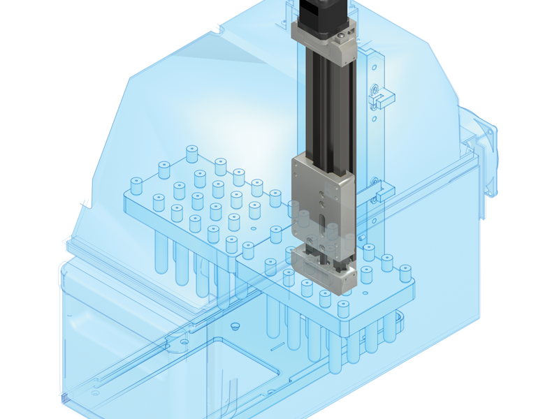
Medical and Laboratory Equipment
Analyzers that are used in medical testing applications often require high accuracy in a small space. SIMO Series can be designed for these specific application requirements with the benefits of available rail, bearing type, and drive options.
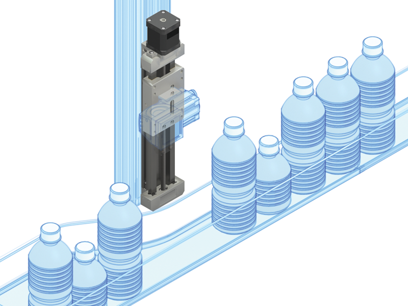
Bottling
The SIMO Series is ideal in bottling and food service applications that require repeatable motion and involve various load capacities. Plain bearings utilize the bonded FrelonGold® selflubricating maintenance-free surface
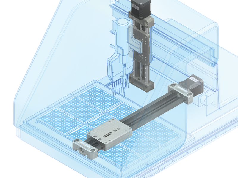
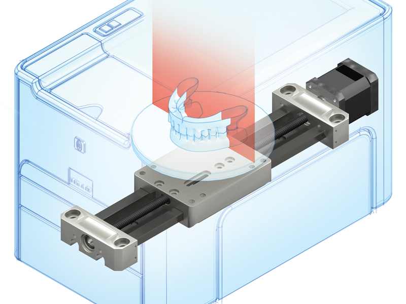
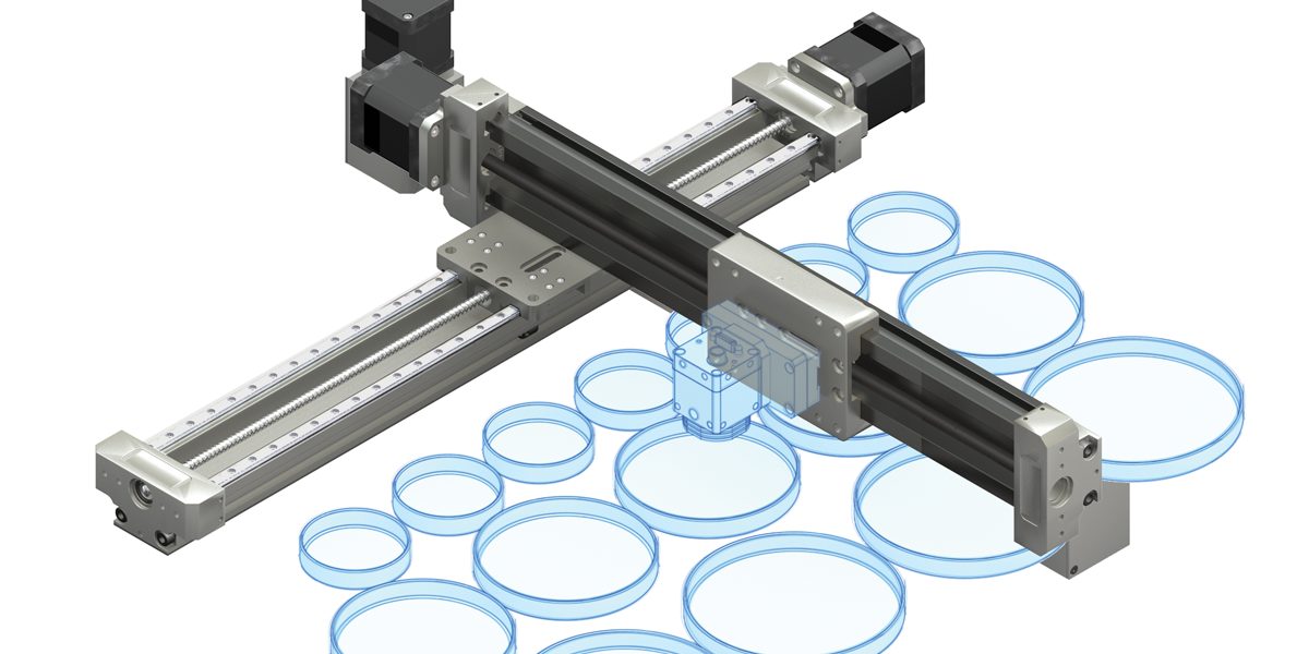
Lab Automation Petri Camera Operation
Combine the SIMO Series bearing options to create the ideal multi-axis solution designed to fit the application.
Shown here:
- X-axis: PRT with ball screw for precision, rigidity, and moment load capabilities
- Y-axis: GST with lead screw for repeatability and smooth motion.
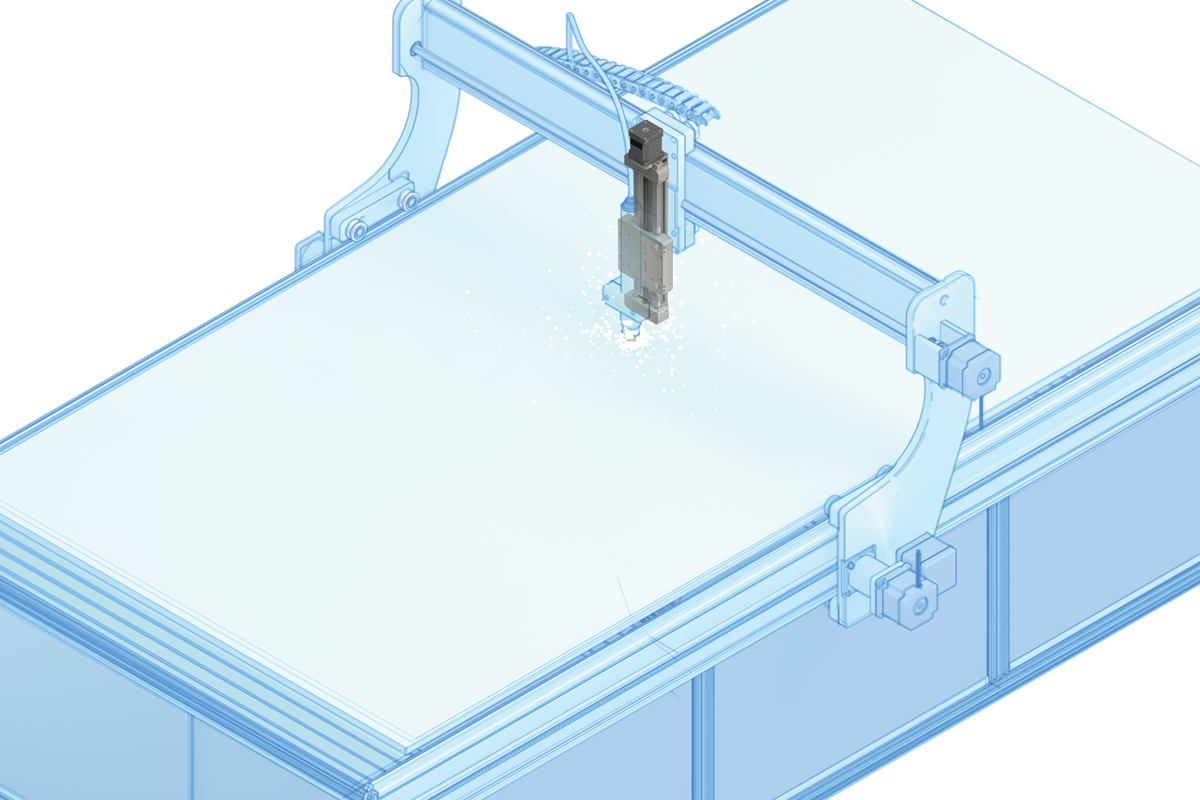
Water Jet
Plasma Cutter XYZ
The SIMO Series is easily integrated into water jet and plasma cutter assemblies. This type of machining requires rigid and precise linear motion and is often located in contaminated, wet, and dirty environments.
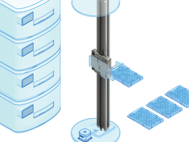
Well Plate Handling
SIMO Series installed in an intricate well plate handler–providing accurate and reliable linear motion.
Commercial Printing
The SIMO Series is a cost effective solution for printers and scanners. The pre-assembled system reduces set-up time and requires little maintenance. V-guide bearings provide quiet, smooth, and dependable motion over long strokes.
SIMO Series Design It Your Way
Step 1 Rail Selection
UGA – Low Profile Rail
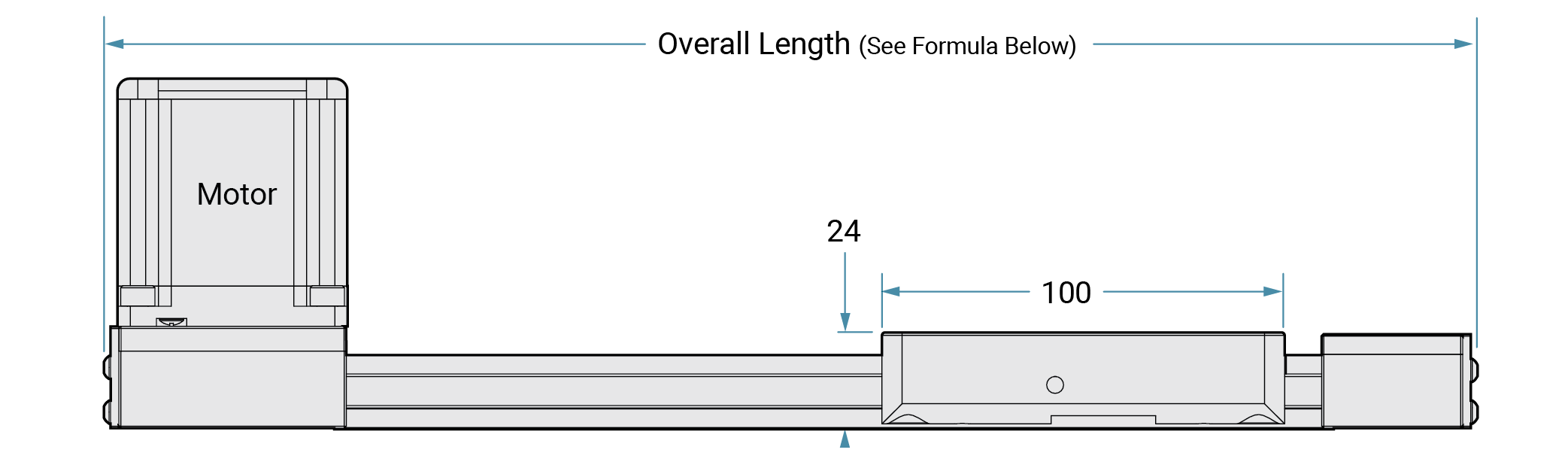
- 24 mm overall height
- Reduced height is ideal for small geometrics
- Best mounted to a base plate or other support
- Can incorporate drive options: lead screw, ball screw, vertical belt
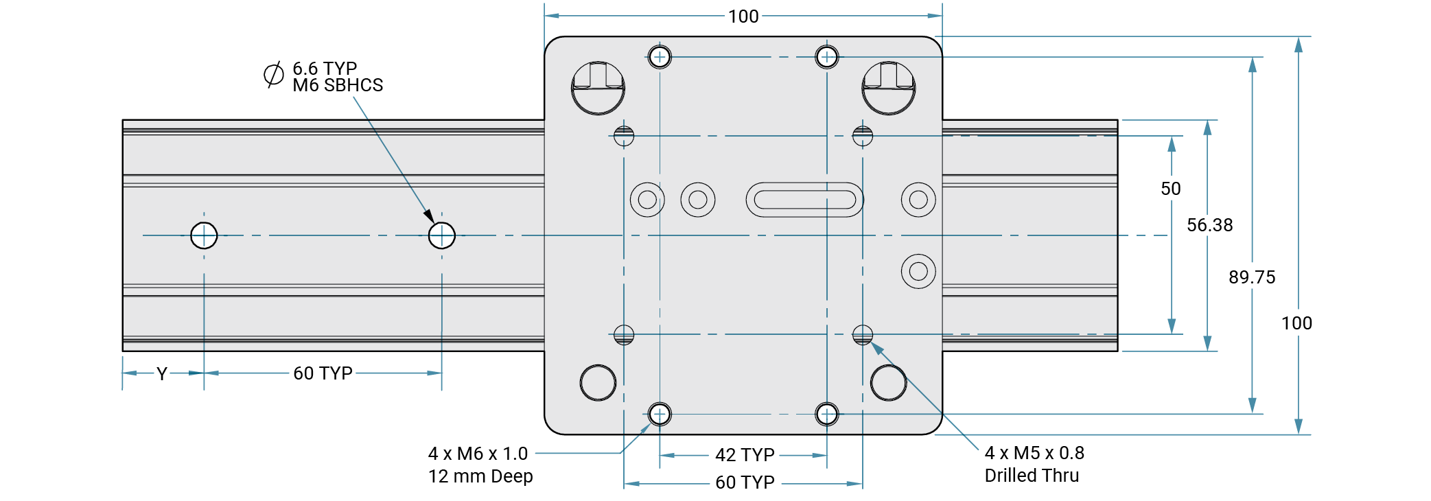
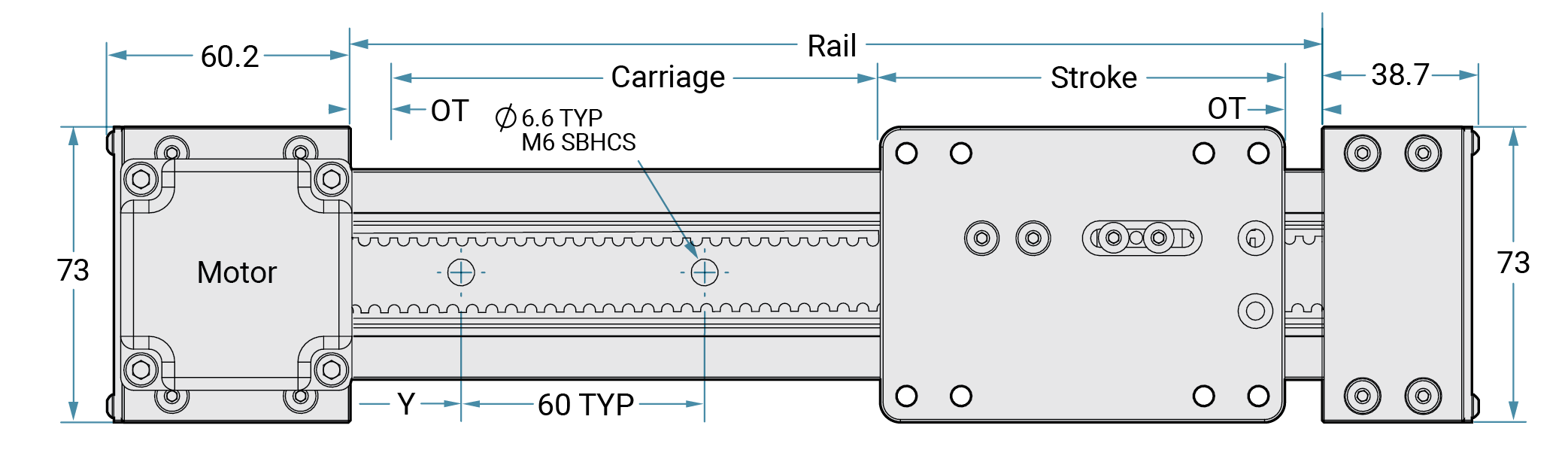
UGA – Low Profile Rail Mounting
- ø6.6 mm holes through rail for mounting with M6 SBHCS
- 60 mm TYP spacing between mounting holes
- Customer specifies first hole distance from end of rail
- End block mounting with lead screw driven systems
UGT - Tall Rail
- 40 mm overall height
- Increased rigidity for unsupported mounting
- Can be used as a structural member
- Saves on the cost of mounting onto another element (extrusion frame, base plate, etc.)
- Can incorporate drive options: lead screw, ball screw, vertical belt, horizontal belt
UGT – Tall Rail Mounting
- Secure toe clamp mounting
- Other options, such as t-nuts, are available when rail is used as a structural element

Rail Material All rails are SIMO qualified aluminum
Reference Edge
- Critical rail edges are machined with the patent pending SIMO® Process
- Reduce bow, twist, and warp
- Holds tolerances to +/- 0.0254 mm (0.001")
- Qualified edges can be used for reference when mounting
Plain Bearing
- Hard anodized
- Best material for FrelonGOLD
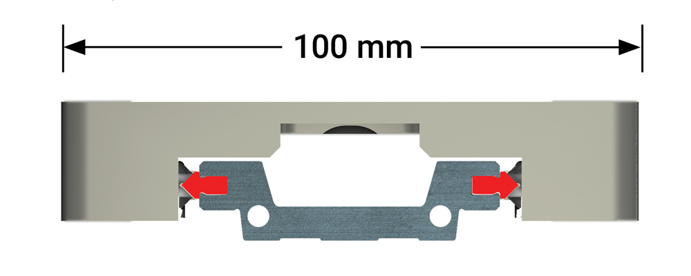
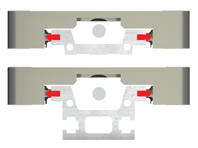
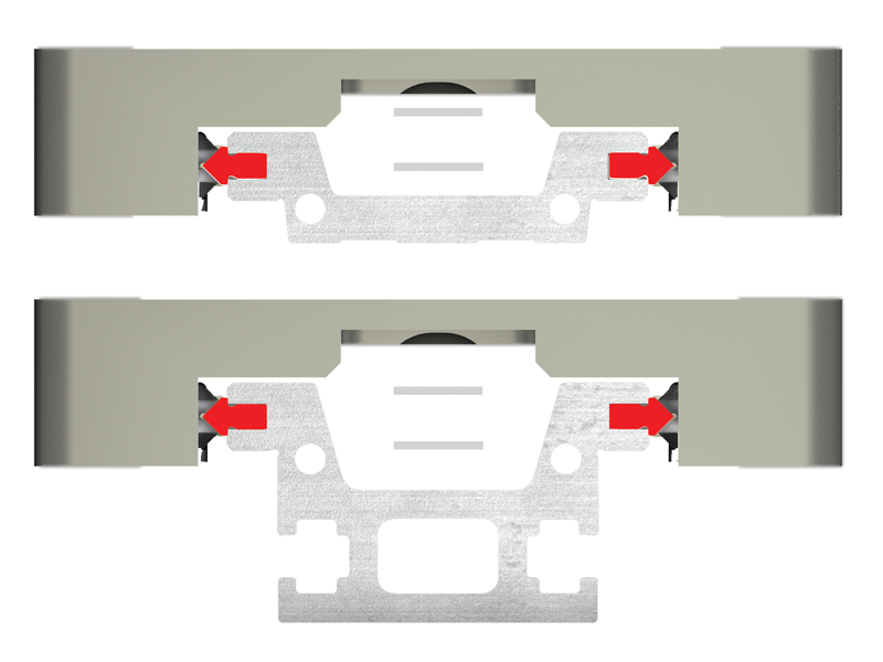
V-Guide Bearings
- Clear anodized
- 420 stainless steel race hardened to RC60 swaged in
Step 2 Bearing System Options
Bearing System Options for SIMO Series Actuators: Plain Bearing or V-Guide Bearings
Choose the bearing system that best supports the application requirements
Gliding Surface Technology
Plain Bearing
- Low cost
- Utilizes bonded FrelonGOLD® bearing surfaces
- Self-lubricating and maintenance free
- No catastrophic failure
- No metal-to-metal contact, vibration damping
- MAX speed: 1.53 m/s (300 ft/min) (dry running)
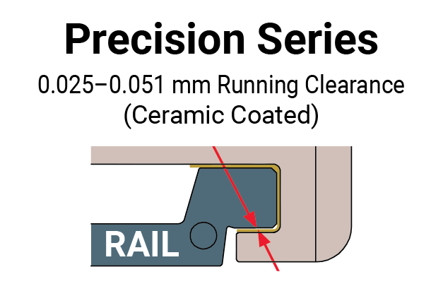
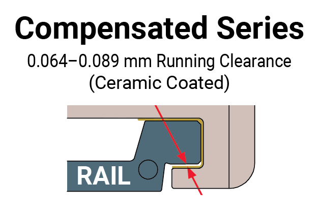
- Precision or compensated running clearance
- Wide temperature range
- Resists contamination
FrelonGold® self-lubricating maintenance-free surface

Note: Plain bearings should comply with the 2:1 ratio rule
Cam Roller Technology
V-Guide Bearings
- High speeds up to 5 m/s (984 ft/min)
- Sealed bearings
- Handles contamination
- Quick change of direction
- Good for cantilevered loads
- Built in lubricators standard
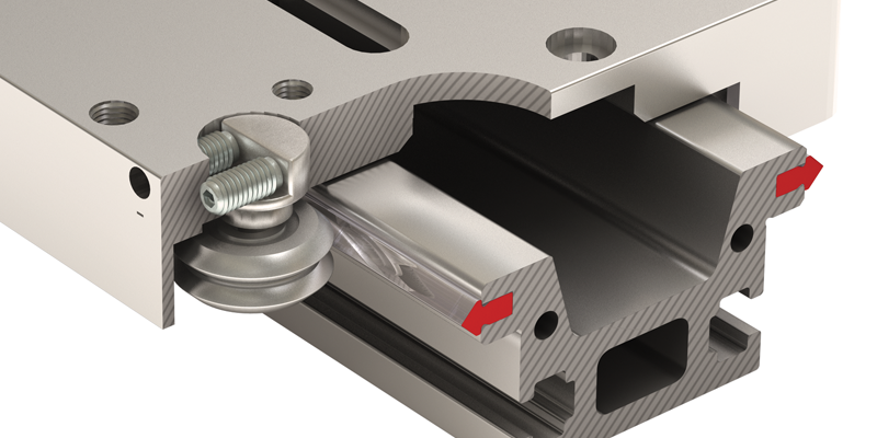
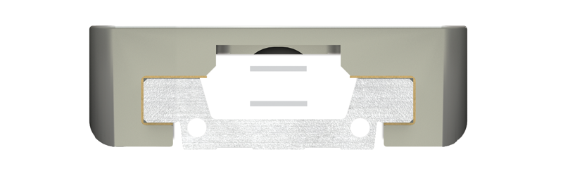
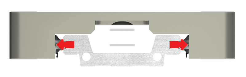
- Patented side-adjust preload feature
- 420 stainless steel race hardened to RC60, swaged in
Double row V-Guide bearings on a hardened steel raceway
Patent pending side adjustment feature

SIMO Series Base Combinations
A choice of bearing systems within the same base linear motion platform
All Critical Surfaces Qualified
Step 3 Drive Type Selection
Drive Type Options for SIMO Series Actuators: Lead Screw or Belt Drive
Choose the drive type that best supports the application requirements
Lead Screw
- Self-lubricating PTFE coated screw and polymer nut
- Fixed nut or Constant Force™ anti-backlash nut available
- 1, 2, 5, 10, 16 mm leads most common
- Other leads available - consult factory
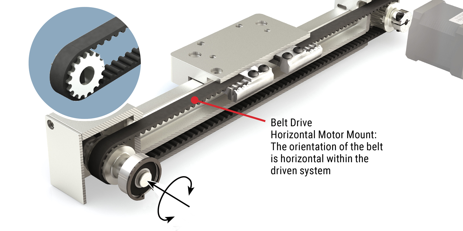
Belt Drive Horizontal Motor Mount
- Ideal for high speed applications
- Horizontal motor mount is available only with (UGT) tall rail

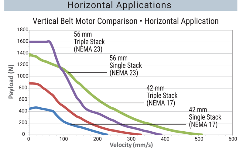
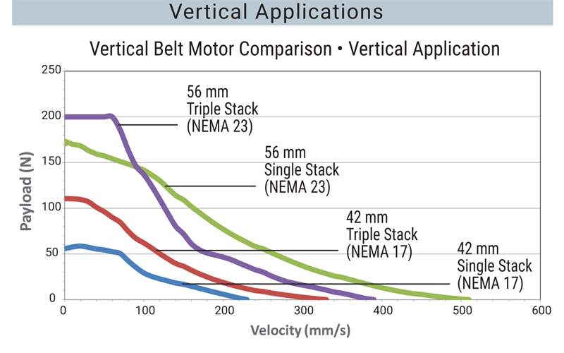
Belt Drive Vertical Motor Mount
- Ideal for high speed applications
- Vertical motor mount is designed only for (UGA) low profile rail
Step 4 Motor Selection
Integrated Stepper Motor
The driven SIMO Series systems are optimized for use with integrated stepper motors.
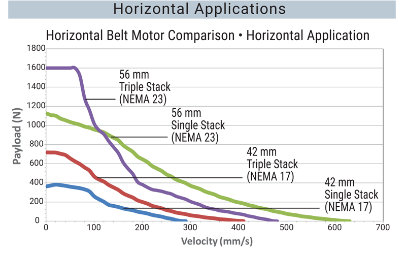
- 42 mm (NEMA 17)
- 56 mm (NEMA 23)
- Single, double, triple stack
- Performance specifications for each drive type:
- Lead screw
- Belt drive with horizontal motor mount
- Belt drive with vertical motor mount
- Ball screw – consult factory
- Standard wire connection is onboard plug
- Optional connections – consult factory
- Third party motor mount also available
Integrated Screw Motor Setup
Integrated lead screw aligned with and fixed directly to motor
- Fewer components
- High accuracy and reliability
- High rigidity
- Space Saving
- Great value
- Motor not field replaceable
Traditional Screw Motor Setup
Traditional screw motor setup optional
- Motor field replaceable
- Requires motor mount option
- Consult factory
Step 5 Select Accessories
Choose the accessories to complete your fully optimized SIMO Series system.
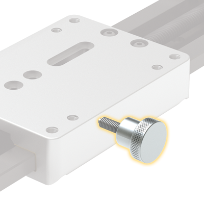
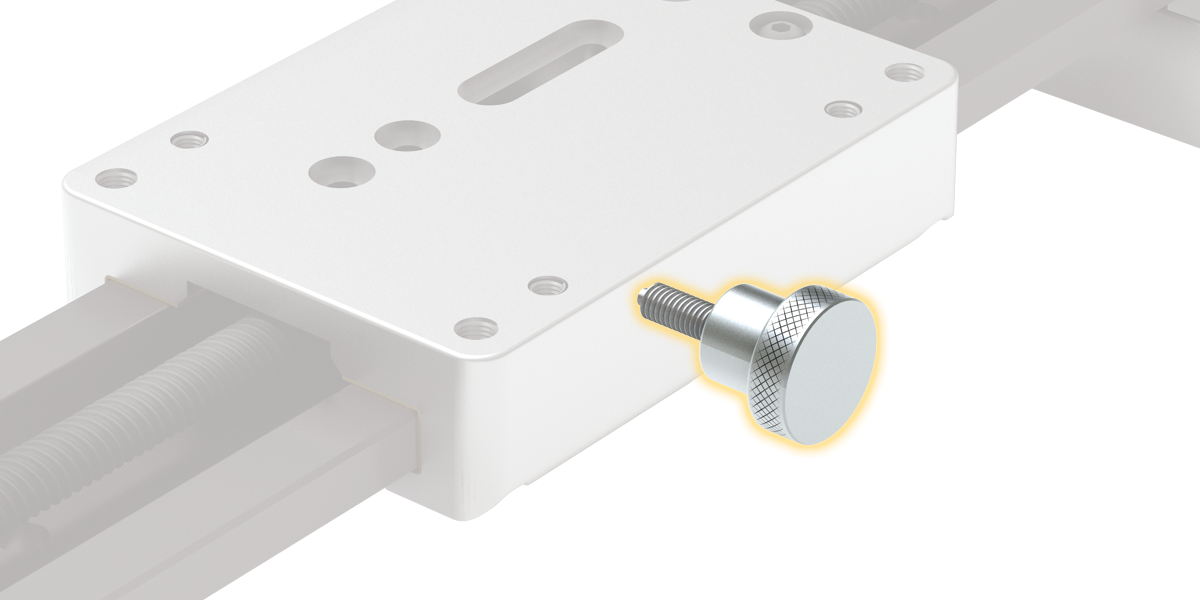
Hand Knob
Hand adjustment knobs are used for manually adjusting screw driven systems
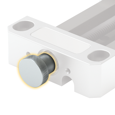
Hand Brake
Hand brakes are used to manually lock position in the GST screw driven systems
Sensor Brackets
Sensor brackets accommodate a variety of sensor types
Motor Mount
Motor mount option for attaching a stepper, servo, or smart motor, etc.

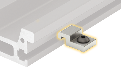
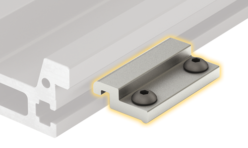
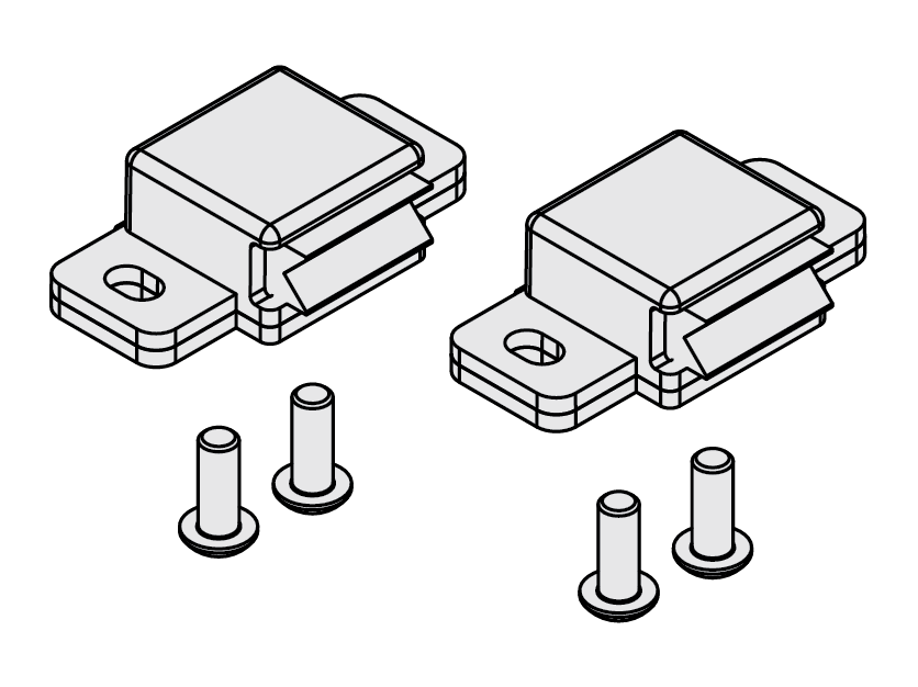
Toe Clamps
Large and small toe clamps are available to secure the (UGT) tall rail to the mounting surface
Riser Block
Riser blocks provide clearance for the motor when using the (UGA) low profile rail
Multi-Axis Mounting Plates
Mounting plates are available to easily configure multi-axis systems
Replacement Lubrication Kits
Replacement lubrication kits are available for GST plain bearing systems and CRT v-wheel bearing systems.
T-Nuts
Roll in t-nut for 5 mm slot with M5 tap PBC Linear part number 6100443.
Custom Option Profile Rail & Ball Screw
High Rigidity • High Precision • High Speeds
Profile Rail Technology
Profile Rail Guideways
- High precision and high speeds – to 3 m/s (590 ft/min)
- Size: 7 mm recirculating ball bearing blocks
- Increased stiffness and preloaded bearing performance
- Supports cantilevered loads
- Extra long blocks for increased load capacity are available – consult factory
- Uniform Rail Dimensions
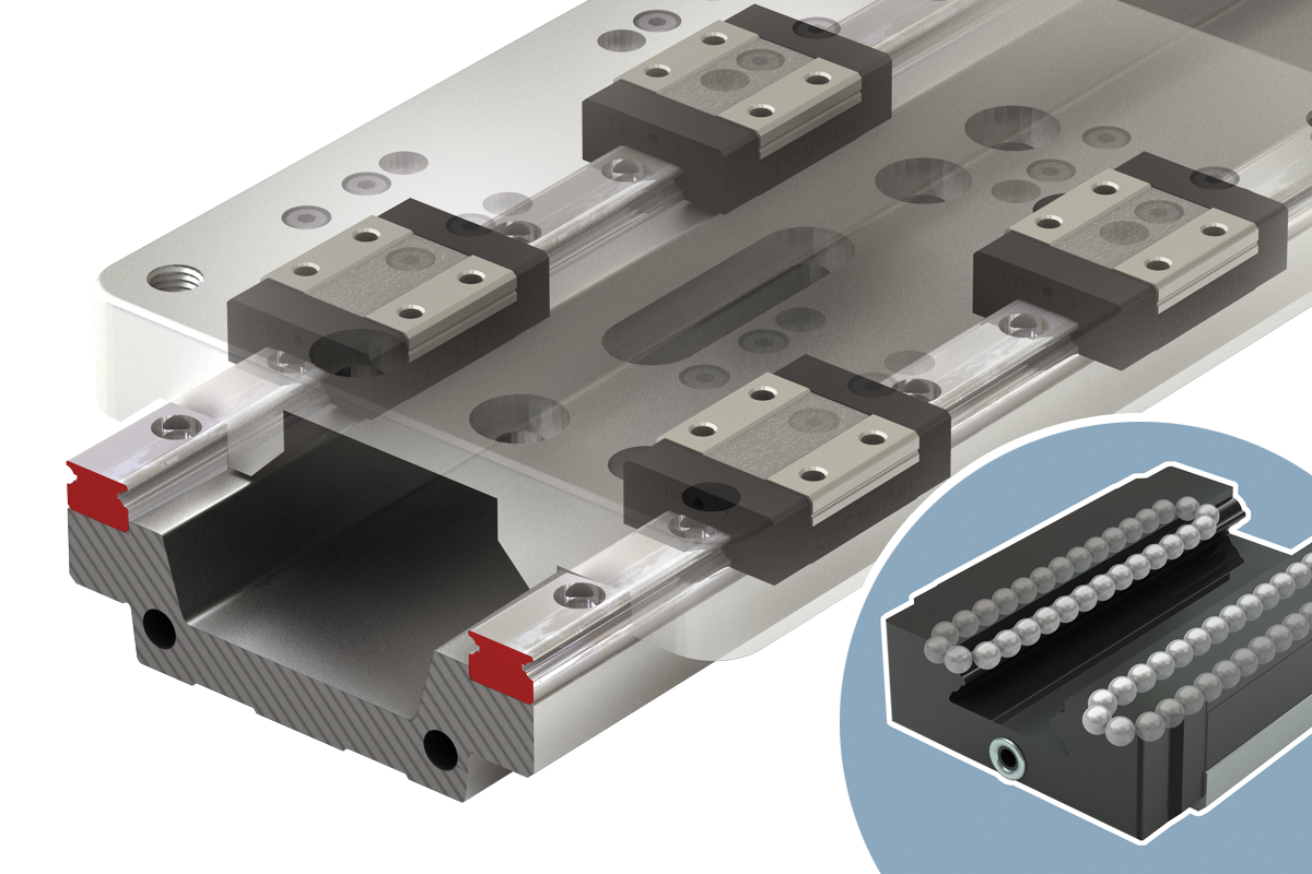
Ball Screw
- Precise positional accuracy applications
- Multiple leads available
- Rigid preload nut design
- Selection of accuracy classes
- Consult factory for options
Plain Bearing Rail & Carriage
Gliding Surface Technology
Plain Bearing
- Low cost
- Utilizes the bonded FrelonGOLD® self-lubricating maintenance-free bearing surfaces
- Ideal for contaminated environments & clean rooms
- Smooth and quiet operation
- Vibration damping and shock resistant

Plain Bearing with FrelonGOLD® Subject to 2:1 cantilevered load rule
Top View
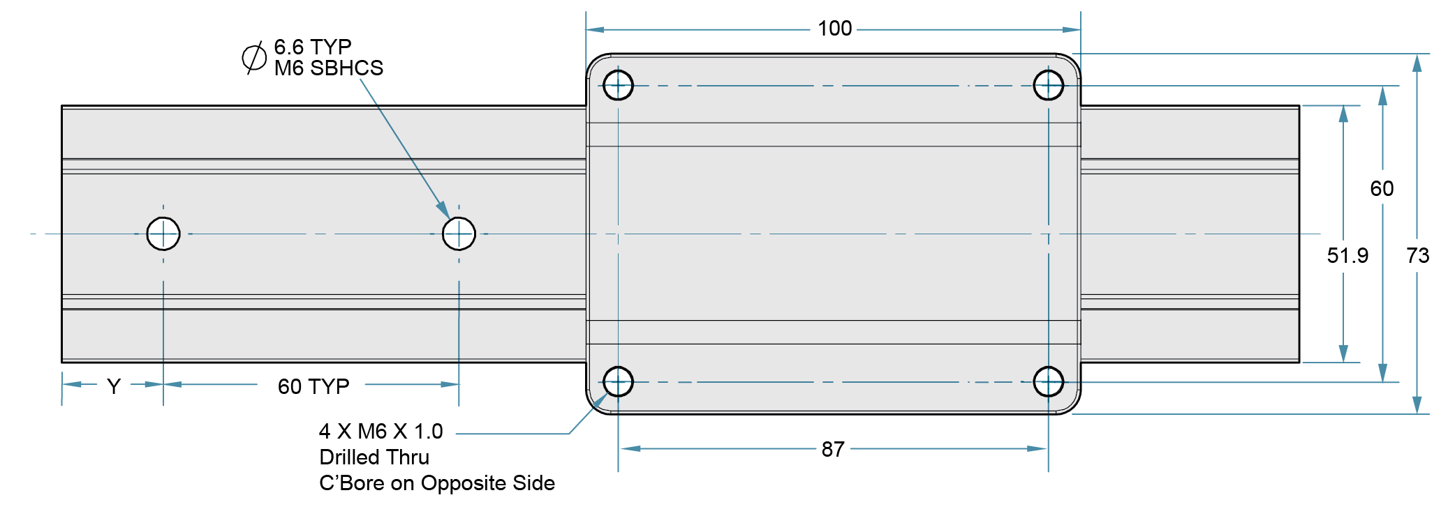
Note: No rail mounting holes in tall rail version (UGT). Tall rail version is mounted with toe clamps. For low profile rail (UGA), specify Y dimension (hole to end) at time of order
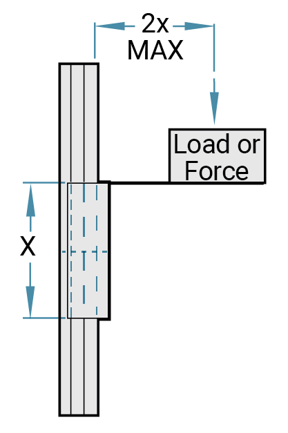
Note: Binding of the carriage will occur if the 2:1 ratio for cantilevered loads and drive forces is exceeded. This principle is not load or force dependent. It is a product of the coefficient of frictions associated with plain bearings. Contact factory or website for additional information.
Rail Ordering Information
| Series | Rail Type | Rail Width | Order Type | Rail Length | Rail Finish | Hole Pattern | Other Options | ||
| UG | X | 040 | R | - | XXXX | - | 0 | X | 0 |
SeriesSIMO SERIES Rail TypeA = Low Profile T = Tall Profile Rail Width040 = 40 mm Order TypeR = Rail Rail Length2750 = 2750 mm max Rail Finish0 = GST Hard Anodized Standard Hole Pattern0 = 60 mm (UGA only – specify Y dimension) 1 = No Holes (UGT only) Other Options0 = Standard |
Ordering example: UGA040R-0280-000; Y = 20 mm. For low profile rail (UGA), specify Y dimension (hole to end) at time of order.
This is a SIMO Series, plain bearing – GST gliding surface technology, low profile rail, 280 mm length.
| GST - Plain Bearing | Low Profile | Tall Profile | ||
|---|---|---|---|---|
| Size | mm | 24 x 73 | 40 x 73 | |
| MAX Static Load* | Fy | N | 3150 | 3150 |
| Fz (Normal) | 6000 | 4710 | ||
| Fz (Inverted) | 2200 | 1640 | ||
| MAX Dynamic Load | Fy | N | 3150 | 3150 |
| Fz (Normal) | 6000 | 4710 | ||
| Fz (Inverted) | 2200 | 1640 | ||
| MAX Moments* | Mx | Nm | 100 | 100 |
| My | 130 | 130 | ||
| Mz | 120 | 120 | ||
| Carriage Bending Moment of Inertia (second moment of area) |
Ly | cm^4 | 48.9 | 48.9 |
| Lz | 51.4 | 51.4 | ||
| Inertia of Carriage | Ly | Kgm2 | 0.000 000 259 | 0.000 000 259 |
| Lz | 0.000 000 348 | 0.000 000 348 | ||
| Coefficient of Friction** μ | 0.125 | 0.125 | ||
| MAX Velocity, no lube, continuous motion | m/s | 1.53 | 1.53 | |
| MAX Velocity, intermittent motion or with lube | m/s | 4.2 | 4.2 | |
| Normal Operating Temperatures - Minimum | °C | 0 | 0 | |
| Normal Operating Temperatures - Maximum | °C | +150*** | +150*** | |
| MAX Rail Length | mm | 2000 | ||
| Carriage Weight | Kg | 0.235 | 0.235 | |
| Rail Weight | Kg/m | 1.067 | 1.727 | |
Conversions
newton (N) x 0.2248 = lb.
newton - meter (N-m) x 8.851 = in.-lb.
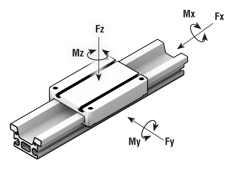
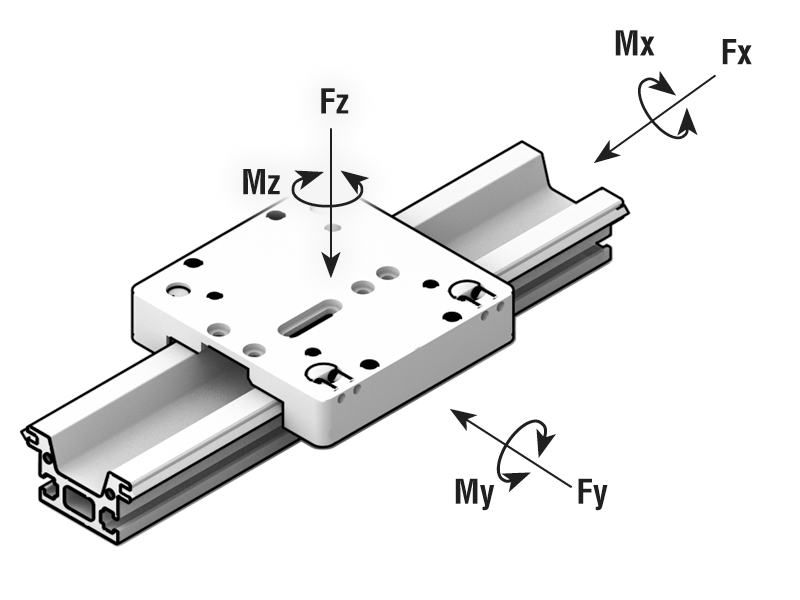
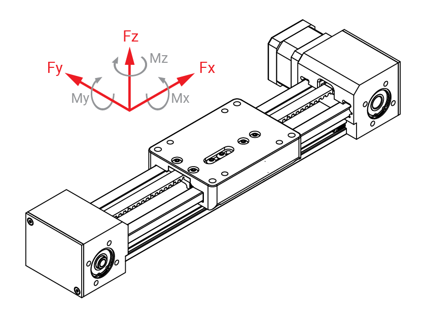
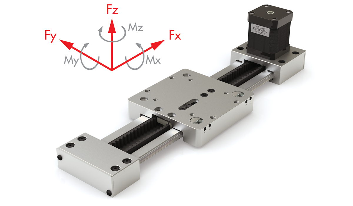
\( F_z \) = Axial capacity
\( F_y \) = Radial capacity
\( M_x, M_y, M_z \) = Moment capacities
* The shown moments and loads are MAX values, please consult our technical department for further information.
** Listed values are for dry application. Adding lubrication can decrease values by up to 50%.
*** Compensated fit carriage
*** Refer to SIMO Series Load Calculations for calculations
Carriage
Carriage Ordering Information
| Series | Rail Type | Rail Width | Order Type | Carriage Length | Running Clearance | Height | Bearing Material | Options | Other Options | |
| UG | A | 040 | C | - | 0 | X | 1 | G | X | 0 |
SeriesSIMO SERIES Rail TypeA = Standard (Used with both low profile & tall rail Rail Width040 = 40 mm Order TypeC = Carriage Carriage Length0 = GST 100 mm Standard Running ClearanceP = Precision 0.025-0.051 mm C = Compensated 0.064–0.089 mm Height1 = Standard carriage with t-slots Bearing MaterialG = FrelonGOLD Standard Options0 = None 1 = Hand Brake 2 = Lube Option 3 = Both Other Options0 = Standard |
Ordering example: UGA040C-0P1G30. This is a SIMO Series carriage, plain bearing – GST gliding surface technology, precision running clearance, with standard FrelonGOLD, hand brake, and lube option.
Note: Driven systems use precision series carriages only
V-Guide Bearings Rail & Carriage
Cam Roller Technology
V-Guide Bearings
- Double row V-Guide roller bearings ride on a hardened stainless steel raceway
- Sealed rollers provide high speed performance and quick change of direction capabilities
- Greater capacity for cantilevered and moment loads
- Patented side-adjustable preload
Double Row V-Guide Bearings
on a Hardened Stainless
Steel Raceway
Top View
Note: No rail mounting holes in tall rail version (UGT). Tall rail version is mounted with toe clamps. For low profile rail (UGA), specify Y dimension (hole to end) at time of order
Rail Ordering Information
| Series | Rail Type | Rail Width | Order Type | Rail Length | Rail Finish | Hole Pattern | Other Options | ||
| UG | X | 040 | R | - | XXXX | - | 2 | X | 0 |
SeriesSIMO SERIES Rail TypeA = Low Profile T = Tall Profile Rail Width040 = 40 mm Order TypeR = Rail Rail Length3600 = 3600 mm max Rail Finish2 = CRT Clear Anodize Standard Hole Pattern0 = 60 mm (UGA only – specify Y dimension) 1 = No Holes (UGT only) Other Options0 = Standard |
Ordering example: UGA040R-0280-200; Y = 20 mm. For low profile rail (UGA), specify Y dimension (hole to end) at time of order.
This is a SIMO Series, V-Guide bearing– CRT cam roller technology, low profile rail, 280 mm length, with a hole-to-end (Y) dimension of 20 mm.
| CRT – V-Guide Bearings | Low Profile | Tall Profile | ||
|---|---|---|---|---|
| Size | mm | 24 x 100 | 40 x 100 | |
| MAX Static Load* | Fy | N | 740 | 740 |
| Fz (Normal) | 880 | 880 | ||
| Fz (Inverted) | 880 | 880 | ||
| MAX Dynamic Load | Fy | N | 740 | 740 |
| Fz (Normal) | 880 | 880 | ||
| Fz (Inverted) | 880 | 880 | ||
| MAX Moments* | Mx | Nm | 15 | 15 |
| My | 25 | 25 | ||
| Mz | 35 | 35 | ||
| Carriage Bending Moment of Inertia (second moment of area) |
Ly | cm4 | 102.6 | 102.6 |
| Lz | 104.4 | 104.4 | ||
| Inertia of Carriage | Ly | Kgm2 | 0.000 000 242 | 0.000 000 242 |
| Lz | 0.000 000 788 | 0.000 000 788 | ||
| Coefficient of Friction** μ | 0.125 | |||
| MAX Velocity, continuous motion | m/s | 5 (requires lubrication) | ||
| MAX Velocity, intermittent motion | m/s | 5.5 | 5.5 | |
| MAX Aceleration | m/s2 | 50 | 50 | |
| Normal Operating Temperatures - Minimum | °C | 0 | 0 | |
| Normal Operating Temperatures - Maximum | °C | +80 | +80 | |
| MAX Rail Length | mm | 2000 | ||
| Carriage Weight | Kg | 0.355 | 0.355 | |
| Rail Weight | Kg/m | 1.305 | 1.979 | |
Conversions
newton (N) x 0.2248 = lb.
newton - meter (N-m) x 8.851 = in.-lb.
\( F_z \) = Axial capacity
\( F_y \) = Radial capacity
\( M_x, M_y, M_z \) = Moment capacities
* The shown moments and loads are MAX values, please consult our technical department for further information.
** Listed values are for dry application. Adding lubrication can decrease values by up to 50%.
*** Compensated fit carriage
*** Refer to SIMO Series Load Calculations for calculations
Carriage
Carriage Ordering Information
| Series | Rail Type | Rail Width | Order Type | Carriage Length | Running Clearance | Height | Bearing Options | Options | Other Options | |
| UG | A | 040 | C | - | 3 | A | 3 | T | X | 0 |
SeriesSIMO SERIES Rail TypeA = Standard (Used with both low profile & tall rail Rail Width040 = 40 mm Order TypeC = Carriage Carriage Length3 = CRT 100 mm Standard Running ClearanceA = Adjustable Height3 = Standard Bearing OptionsT = Stainless Steel Sealed Options1 = Lube Option Standard 0 = None (Contact factory before ordering) Other Options0 = Standard |
Ordering example: UGA040C-3A3T10. This is a SIMO Series carriage, V-Guide – CRT cam roller technology, adjustable, with lube option.
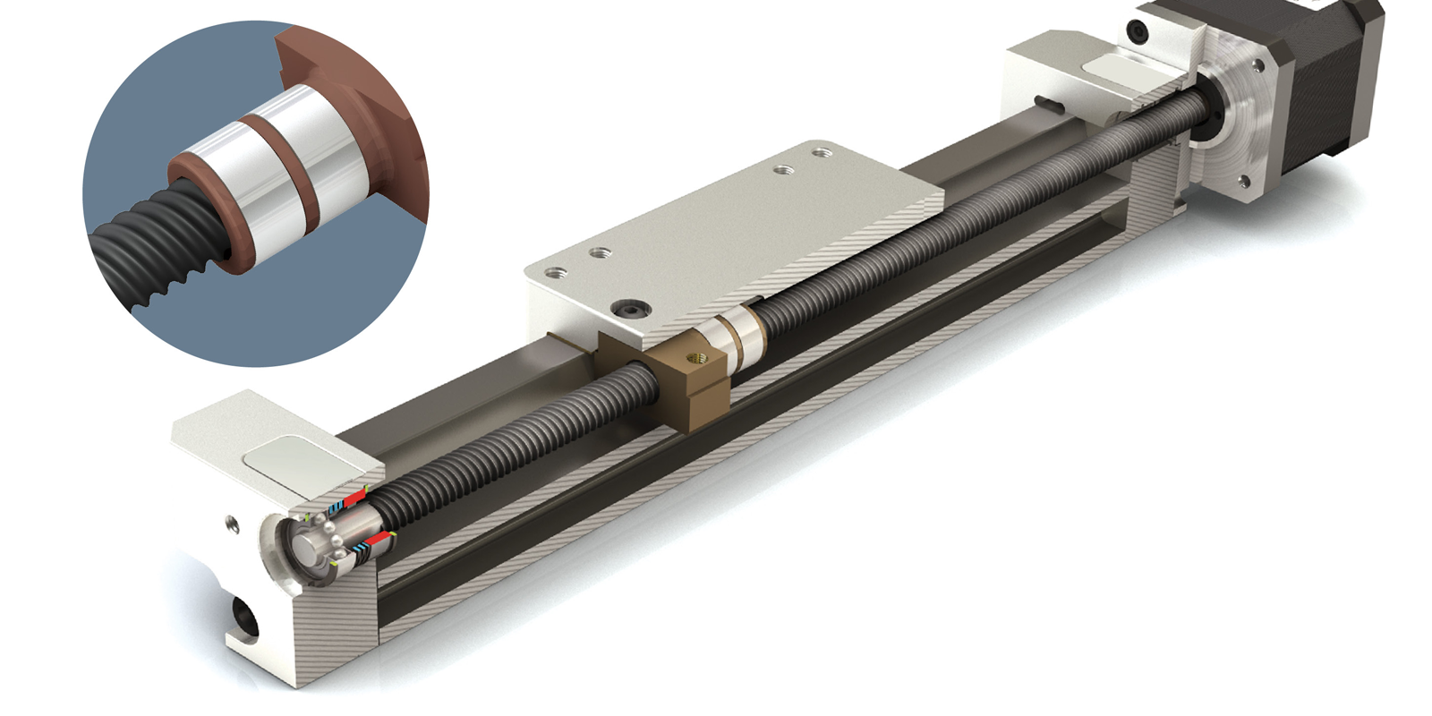
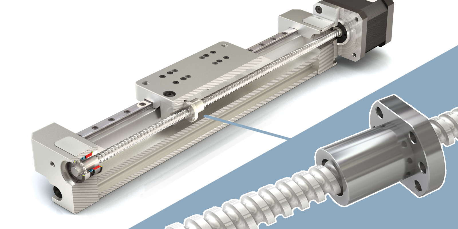
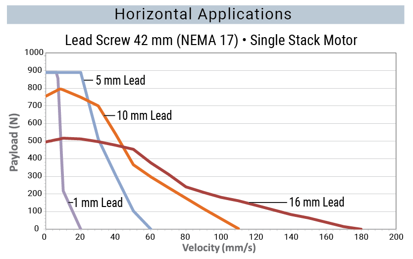
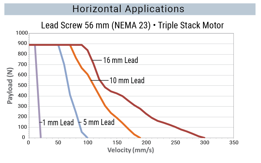
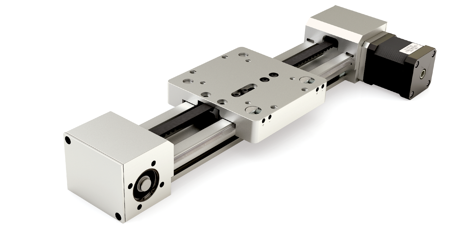
Lead Screw Driven System
Overview
- Utilizes a self-lubricating and maintenance free nut
- Standard fixed nut or Constant Force anti-backlash nut available
- Lead screw material:
- 10 mm diameter
- 300 series stainless steel with PTFE coating
- 1, 2, 5, 10, 16 mm leads most common
- Other leads available – consult factory
- Ideal for a broad range of applications such as kiosks, assembly, automation, medical, and laboratory
Motor Options and Benefits
- Standard integrated screw stepper motors
- 42 mm (NEMA 17)
- 56 mm (NEMA 23)
- Integrated lead screw eliminates components and tolerance stack-ups
- Improves rigidity and performance
- Reduces system cost
Accessories
- Hand knobs – for manual positioning or applications that require precision adjustment
- Riser blocks
- Toe clamps and t-nuts
- Brake knobs
- Optional motor mounts
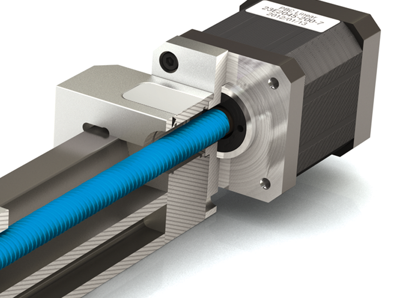
Drive end screw support bearings are integrated into the stepper motor

Patented Constant Force Technology nuts provide consistent anti-backlash operation
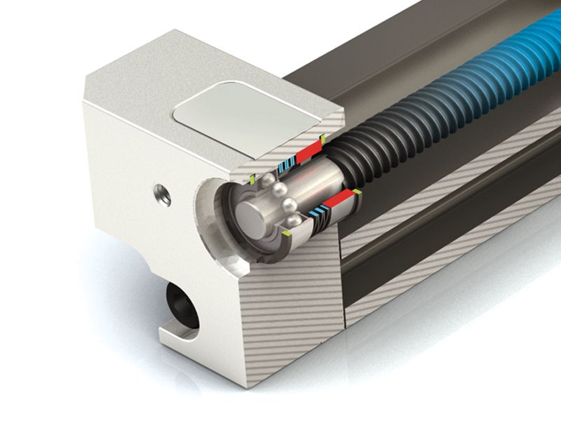
Ball bearings provide idle end screw support
GST: Plain Bearing
Low Profile Rail / Tall Rail
CRT: V-Guide
Low Profile Rail / Tall Rail
| Basic System Properties | |||
|---|---|---|---|
| MAX Velocity, no lube, continuous motion |
m/s | 1.5 | requires lubrication |
| MAX Velocity, intermittent motion |
m/s | 4.2 (with lubrication) |
5.5 (requires lubrication) |
| MAX Acceleration*** | m/s2 | 50 | 50 |
| Stroke Length (MIN recommended – MAX)*** |
mm | 5 - 1400 | 5 - 1400 |
| Normal Operating Temperatures (MIN - MAX) |
°C | 0° - 80° | |
| MAX Drive (input) Speed | rpm | 3000**** | |
| Standard Lead Screw Accuracy |
ISO CLASS 10 (± .0007 mm/mm) |
||
| Carriage Weight | Kg | 0.235 | 0.355 |
| Rail + Screw Weight | Kg/m | 1.690 / 2.356 | 1.909 / 2.578 |
| System Weight (excluding motor) |
Kg | 0.41 + (1.69 * length) / 0.5 + (2.356 * length) |
0.53 + (1.909 * length) / 0.62 + (2.578 * length) |
| Static & Dynamic System Properties | ||||
|---|---|---|---|---|
| MAX Static Load* | Fx | N | 111.2 | |
| Fy | 3150 | 740 | ||
| Fz (Normal) | 6000 / 4710 | 880 | ||
| Fz (Inverted) | 2220 / 1640 | 880 | ||
| Nut Thrust Capacity (See PV derate chart) | Fx Standard Nut | N | 445 | |
| Fx Anti-Backlash | 400 | |||
| MAX Dynamic Load* (For PBC Linear supplied motor, refer to charts below) |
Fx | N | 111.2 | |
| Fy | 890 | 740 | ||
| Fz (Normal) | 890 | 880 | ||
| Fz (Inverted) | 890 | 880 | ||
| MAX Moments* | Mx | Nm | 100 | 15 |
| My | Nm | 130 | 25 | |
| Mz | Nm | 120 | 35 | |
*The above moments and loads are MAX values, please consult our technical department for further information.
**Refer to Assembly Procedure for combined load calculations.
***Increased acceleration may be possible in limited cases. Consult factory if exceeding limit.
**** Reduced Fx dynamic nut load capacity in compliance with PV derate chart to the right here.
PBC Linear Load Derate Factor for Metric Lead Screw Nuts

MAX Nut Load = Cf x Nut Dynamic
Load Rating
Please note that the PV limit of the nut is dependent on the duty of the application and other factors so these curves are a guideline. If your application will operate near or beyond the shown curves, please contact PBC Linear for support.


Note: Based on 500 mm stroke, GST version with 0.125 C.O.F. and 0.3G acceleration. Based on 24 volt, but higher voltage amplifiers may produce higher speeds.
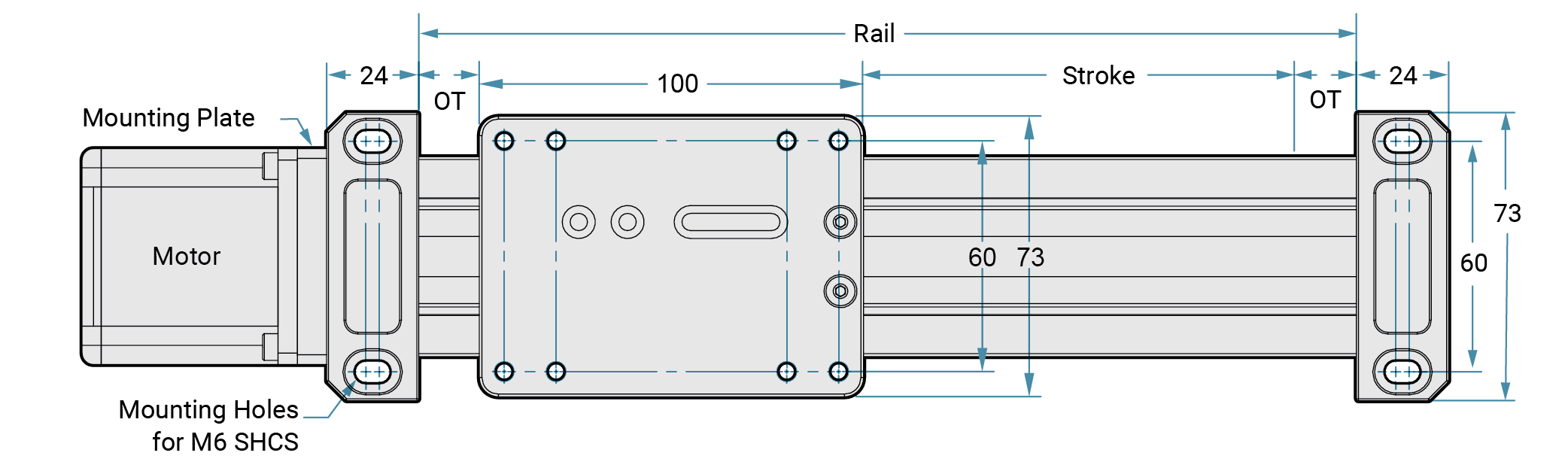
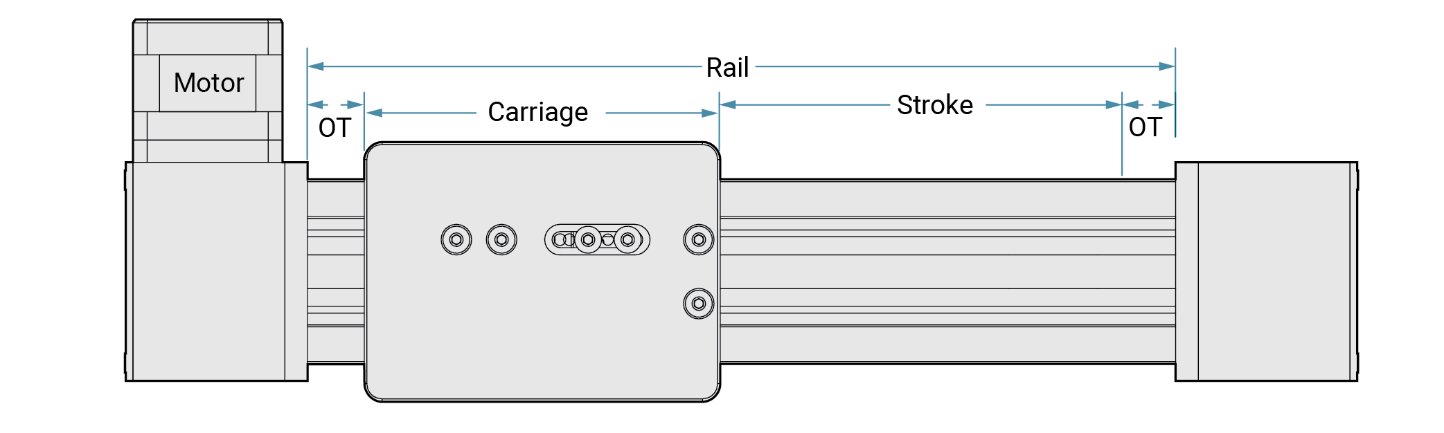
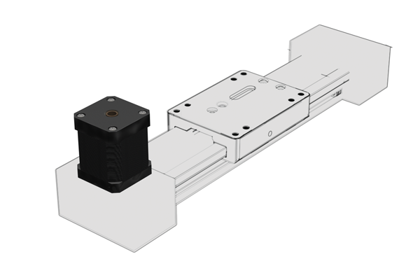
System Dimensions
Top View
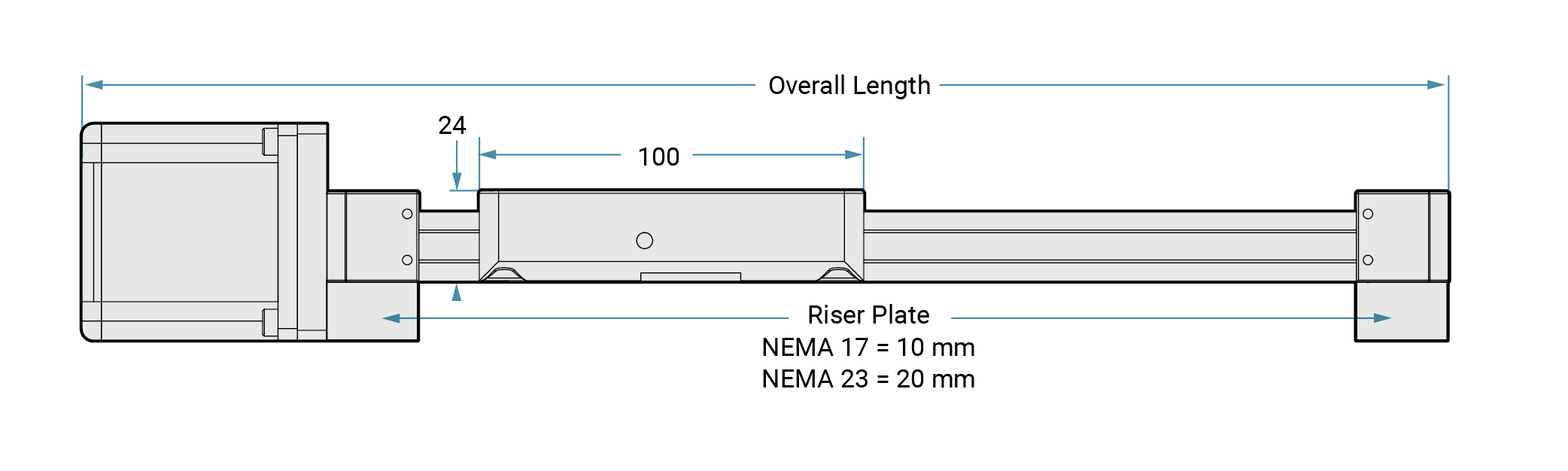
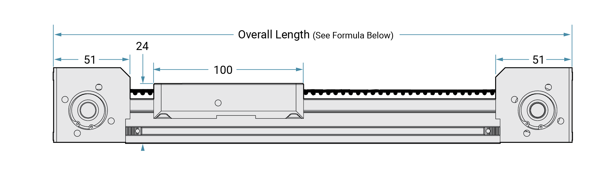
Side View
Paragraph
Side View UGA Low Rail
Side View UGT Tall Rail
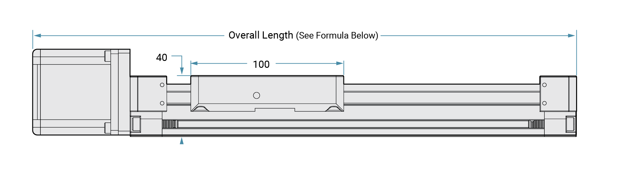
Note: GST bearing system shown
Motor Lengths (Plus Mounting Plate)
| Motor Size | Single Stack | Double Stack | Triple Stack |
|---|---|---|---|
| 42 mm (NEMA 17) | 40 mm | 48 mm | 61 mm |
| 56 mm (NEMA 23) | 55 mm | 77 mm | 77 mm |
Note: Sizes shown include 7.8 mm width for motor mounting plate.
Required for SIMO Series driven systems:
Minimum overtravel (OT)
- 10 mm for ≤ 300 mm stroke
- 25 mm for > 300 mm stroke
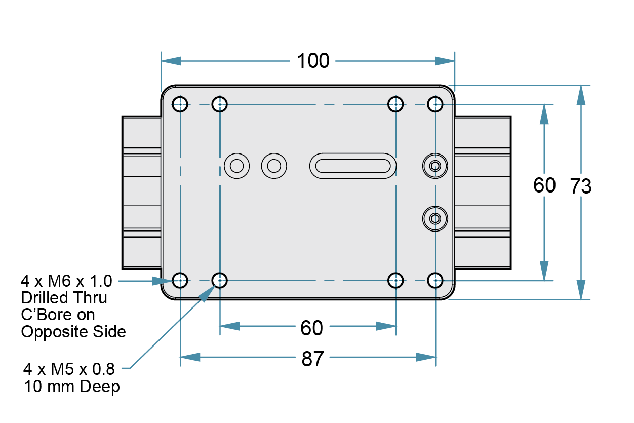
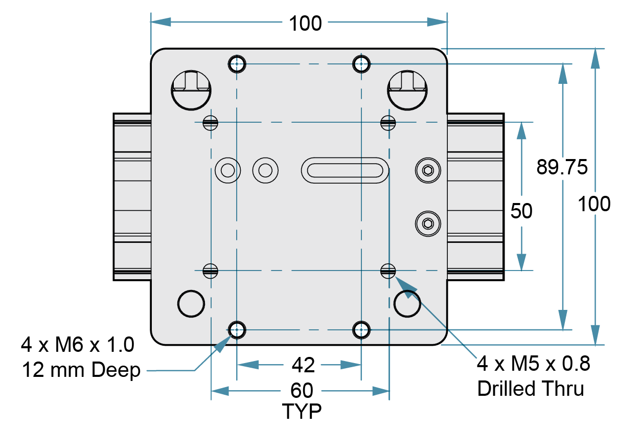
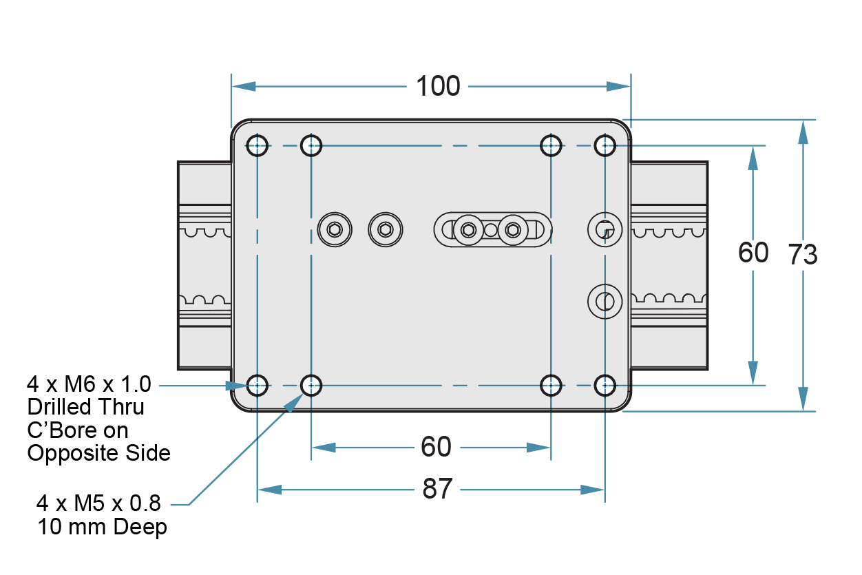
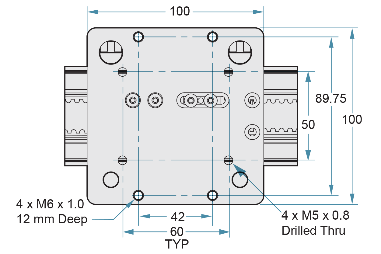
Top View
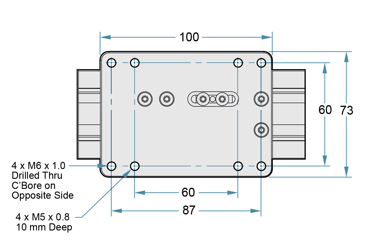
Carriage Dimensions
Gliding Surface Technology Plain Bearing
Cam Roller Technology V-Guide Bearings
System Ordering Information
| Series | Rail Type | Rail Width | Order Type | Carriage Type | Options | Rail Length | Drive Type | Drive End Option | Motor Option | Lead (mm) | Nut | Accuracy | Other Options | |||||
| UG | X | 040 | D | - | XX | X | - | XXXX | - | LS | X | XX | - | XX | X | 1 | - | 0 |
SeriesSIMO SERIES Rail TypeA = Low Profile T = Tall Profile Rail Width040 = 40 mm Order TypeD = Driven Carriage TypeA1 = GST with FrelonGOLD B2 = V-Guide with Stainless Steel Sealed Rollers & Lubrication Options0 = None 1 = Hand Brake 2 = Lube 3 = Both 1 = Lube (required) Rail Length1500 = 1500 mm MAX Consult factory for longer lengths Drive TypeLS = Lead Screw Drive End Option1 = Shaft or MTA MT 2 = Knob 3 = PBC Linear Integrated Motor Screw For custom options consult an application engineer at PBC Linear, 800-962-8979. Motor Option00 = No Motor/Stub Shaft Only A1 = 42 mm (N17) Single Stack A2 = 42 mm (N17) Double Stack B4 = 56 mm (N23) Single Stack B5 = 56 mm (N23) Double Stack B6 = 56 mm (N23) Triple Stack Third Party MTR MT Options ZE = 40 mm ZF = 42 mm (N17) ZG = 56–58 mm (N23) ZH = 60 mm Z0 = Blank Plate For custom options consult an application engineer at PBC Linear, 800-962-8979. Lead (mm)AF = 16 AJ = 10 AX = 5 AG = 2 AH = 1 AW = 25 BD = 12 BH = 8 BG = 6 AR = 4 Consult factor for other leads Nut1 = Standard 2 = Anti-Backlash Accuracy1 = Class 10 Other Options0 = 1/1 1 = 2/1 2 = 2/2 3 = 3/1 4 = 3/2 5 = 3/3 6 = 4/1 7 = 4/2 8 = 4/3 9 = 4/4 # Carriages/Master car poition from drive end |
Ordering example: UGT040D-A10-0900-LS3A1-AF11-0.
This is a SIMO Series, plain bearing – GST gliding surface technology, tall profile rail, 900 mm length, lead screw driven, PBC Linear integrated motor screw, 42 mm (NEMA 17) single stack motor, 16 mm lead, standard nut, accuracy class 10.
Belt Drive System
Horizontal Motor Mount
Overview
- Horizontal motor mount available in the tall profile (UGT) only
- Ideal for higher speed, high duty cycle applications
- Belt material: nylon covered, fiberglass reinforced, neoprene
- Temperature range: 0° C to +80° C (32° F to 176° F)
- Rounded GT®2 tooth design creates better engagement with the pulley resulting in greater torque transfer, reduced vibration, and extended life
Motor Options and Benefits
- Standard integrated screw stepper motors
- 42 mm (NEMA 17)
- 56 mm (NEMA 23)
- Split collar connection to integrated pulley
- Integrated shaft reduces pulley runout
- Reduces system cost
- Optional stub shaft and motor adapter plate – consult factory
Accessories
- Sensor brackets
- Toe clamps and t-nuts
- Covers
- Optional motor mounts

Split collar drive shaft connects integrated pulley shaft and motor

Independent belt clamps allow for tensioning adjustments

Idle end pulley incorporates integrated shaft design
GST
Plain Bearing
Tall Rail Only
CRT
V-Guide
Tall Rail Only
| Basic System Properties | |||
|---|---|---|---|
| MAX Velocity, no lube, continuous motion | m/s | 1.5 | Requires Lubrication |
| MAX Velocity, intermittent motion or with lube | m/s | 4.2 | 5.5 |
| MAX Acceleration *** | m/s2 | 50 | 50 |
| Stroke Length (MIN recommended) | mm | 5 | 5 |
| Stroke Length (Maximum) | mm | 1900 | 1900 |
| Belt Type & Size | GT®2 - 5 mm | ||
| MAX Drive (input) Torque | Nm | 2.31 | |
| Pulley Ratio | mm/rev | 80 | |
| Pulley Pitch Diameter | mm | 25.5 | |
| MAX Drive (input) Speed | rpm | 3000 | |
| Normal Operating Temperatures - MIN – MAX | °C | 0° - 80° | |
| Carriage Weight | Kg | 0.235 | 0.355 |
| Rail + Belt Weight | Kg/m | 1.73 | 1.98 |
| System Weight (excluding motor) | Kg | 0.5 + (1.73 * length) | 0.62 + (1.98 * length) |
| Static & Dynamic System Properties | ||||
|---|---|---|---|---|
| MAX Static Load* | Fx | N | 200 | |
| Fy | 3150 | 740 | ||
| Fz (Normal) | 4710 | 880 | ||
| Fz (Inverted) | 1640 | 880 | ||
| MAX Dynamic Load* (For PBC Linear supplied motor, refer to charts below) |
Fx | N | 200 | |
| Fy | 1600 | 740 | ||
| Fz (Normal) | 1600 | 880 | ||
| Fz (Inverted) | 1600 | 880 | ||
| MAX Moments* | Mx | Nm | 100 | 15 |
| My | Nm | 130 | 25 | |
| Mz | Nm | 120 | 35 | |
| Coefficient of Friction (linear guide) | μ | 0.125 | 0.02 | |
*The above moments and loads are MAX values, please consult our technical department for further information.
**Refer to Assembly Procedure for combined load calculations.
***Increased acceleration may be possible in limited cases. Consult factory if exceeding limit.

Note: Based on 2 m stroke, .125 C.O.F., and .3G acceleration. Use caution when applying a belt drive in a vertical application. Higher voltage amplifiers may produce higher speeds.
System Dimensions
Top View
Side View
Paragraph
Side View UGT Tall Rail
Note: GST bearing system shown
Motor Lengths (Plus Mounting Plate)
| Motor Size | Single Stack | Double Stack | Triple Stack |
|---|---|---|---|
| 42 mm (NEMA 17) | 40 mm | 48 mm | 61 mm |
| 56 mm (NEMA 23) | 55 mm | 77 mm | 77 mm |
Required for SIMO Series driven systems:
Minimum overtravel (OT)
- 10 mm for ≤ 300 mm stroke
- 25 mm for > 300 mm stroke
Motor Locations
Left
Right
Note: Specify motor location (in part number) for PBC Linear integrated motors. Contact factory for stub shaft and optional motor mounting plates.
Top View
Carriage Dimensions
Gliding Surface Technology Plain Bearing
Cam Roller Technology V-Guide Bearings

System Ordering Information
| Series | Rail Type | Rail Width | Order Type | Carriage Type | Options | Rail Length | Drive Type | Drive End Option | Motor Option | Lead (mm) | Motor Position | Accuracy | #* Carriages | |||||
| UG | T | 040 | D | - | XX | X | - | XXXX | - | BD | X | XX | - | 00 | X | 0 | - | 0 |
SeriesSIMO SERIES Rail TypeT = Tall Profile Rail Width040 = 40 mm Order TypeD = Driven Carriage TypeA1 = GST with FrelonGOLD B2 = V-Guide with Stainless Steel Sealed Rollers & Lubrication Options0 = None 1 = Hand Brake 2 = Lube 3 = Both 1 = Lube (required) Rail Length2000 = 2000 mm MAX Consult factory for longer lengths Drive TypeBD = Belt Drive Drive End Option1 = Standard For custom options consult an application engineer at PBC Linear, 800-962-8979. Motor Option00 = No Motor/Stub Shaft Only Integrated Motor B4 = 56 mm (N23) Single Stack B5 = 56 mm (N23) Double Stack B6 = 56 mm (N23) Triple Stack Third Party Motor Mount 1ZE = 40 mm 1ZF = 42 mm (N17) 1ZG = 56–58 mm (N23) 1ZH = 60 mm 1Z0 = Blank Plate For custom options consult an application engineer at PBC Linear, 800-962-8979. Lead (mm)00 = Not Used Motor PositionL = Left R = Right D = Dual Stub Shaft DL = Dual Stub Shaft Left Mount DR = Dual Stub Shaft Right Mount Accuracy0 = Not Used #* Carriages0 = 1/1 1 = 2/1 2 = 2/2 3 = 3/1 4 = 3/2 5 = 3/3 6 = 4/1 7 = 4/2 8 = 4/3 9 = 4/4 # Carriages/Master car poition from drive end. |
Ordering example: UGT040D-A10-0900-BD1A1-00L0-0.
This is a SIMO Series, plain bearing – GST gliding surface technology, tall profile rail, 900 mm length, belt driven, 42 mm (NEMA 17) single stack motor, positioned on the left.
*Note: Additional carriages are idlers.
Belt Drive System
Vertical Motor Mount

Overview
- Vertical motor mount allows for high speed performance in the (UGA) low profile rail
- Consult factory for (UGT) tall rail with vertical motor mount
- Belt material: nylon covered, fiberglass reinforced, neoprene
- Temperature range: 0° C to +80° C (-32° F to +176° F)
- Rounded GT®2 tooth design creates better engagement with the pulley resulting in greater torque transfer, reduced vibration, and extended life
Motor Options and Benefits
- Standard integrated screw stepper motors
- 42 mm (NEMA 17)
- 56 mm (NEMA 23)
- Integrated drive end pulley eliminates runout
- Reduces system cost
- Optional stub shaft and motor adapter plate – consult factory
Accessories
- Riser Blocks
- Sensor brackets
- Brake knobs
- Covers

Drive end pulley is directly integrated with motor shaft

Independent belt clamps allow for tensioning adjustments

Idle end pulley incorporates integrated shaft design
GST
Plain Bearing
Low Profile Rail
Consult Factory for Tall Rail Options
CRT
V-Guide
Low Profile Rail
Consult Factory for Tall Rail Options
| Basic System Properties | |||
|---|---|---|---|
| MAX Velocity, no lube, continuous motion | m/s | 1.5 | Requires Lubrication |
| MAX Velocity, intermittent motion or with lube | m/s | 4.2 | 5.5 |
| MAX Acceleration *** | m/s2 | 50 | 50 |
| Stroke Length (MIN recommended) | mm | 5 | 5 |
| Stroke Length (Maximum) | mm | 1900 | 1900 |
| Belt Type & Size | GT®2 - 5 mm | ||
| Normal Operating Temperatures - MIN – MAX | °C | 0°-80° | |
| Pulley Ratio | mm/rev | 65 | |
| Pulley Pitch Diameter | mm | 20.7 | |
| MAX Drive (input) Torque | Nm | 2.31 | |
| MAX Drive (input) Speed | rpm | 3000 | |
| Carriage Weight | Kg | 0.235 | 0.355 |
| Rail + Belt Weight | Kg/m | 1.0806 | 1.7496 |
| System Weight (excluding motor) | Kg | 0.41 + (1.0806 * length) | 0.53 + (1.7496 * length) |
| Static & Dynamic System Properties | ||||
|---|---|---|---|---|
| MAX Static Load* | Fx | N | 200 | |
| Fy | 3150 | 740 | ||
| Fz (Normal) | 6000 | 880 | ||
| Fz (Inverted) | 2220 | 880 | ||
| MAX Dynamic Load* (For PBC Linear supplied motor, refer to charts below) |
Fx | N | 200 | |
| Fy | 1600 | 740 | ||
| Fz (Normal) | 1600 | 880 | ||
| Fz (Inverted) | 1600 | 880 | ||
| MAX Moments* | Mx | Nm | 100 | 15 |
| My | Nm | 130 | 25 | |
| Mz | Nm | 120 | 35 | |
| Coefficient of Friction (linear guide) | μ | 0.125 | 0.02 | |
*The above moments and loads are MAX values, please consult our technical department for further information.
**Refer to Assembly Procedure for combined load calculations.
***Increased acceleration may be possible in limited cases. Consult factory if exceeding limit.
Note: Based on 2 m stroke, .125 C.O.F., and .3G acceleration. Use caution when applying a belt drive in a vertical application. Higher voltage amplifiers may produce higher speeds.
System Dimensions
Top View
Side View
Paragraph
Side View UGA Low Profile Rail
Note: GST bearing system shown. For low profile rail (UGA), specify Y dimension (hole to end) at time of order. No rail mounting holes in tall rail version (UGT). Tall rail version is mounted with toe clamps. Consult factory for (UGT) tall rail options.
Motor Lengths (Plus Mounting Plate)
| Motor Size | Single Stack | Double Stack | Triple Stack |
|---|---|---|---|
| 42 mm (NEMA 17) | 40 mm | 48 mm | 61 mm |
| 56 mm (NEMA 23) | 55 mm | 77 mm | 77 mm |
Required for SIMO Series driven systems:
Minimum overtravel (OT)
- 10 mm for ≤ 300 mm stroke
- 25 mm for > 300 mm stroke
Motor Locations
Top
Note: Specify motor location (in part number) for PBC Linear integrated motors. Contact factory for stub shaft and optional motor mounting plates
Top View
Carriage Dimensions
Gliding Surface Technology Plain Bearing
Cam Roller Technology V-Guide Bearings
System Ordering Information
| Series | Rail Type | Rail Width | Order Type | Carriage Type | Options | Rail Length | Drive Type | Drive End Option | Motor Option | Lead (mm) | Motor Position | Accuracy | #* Carriages | |||||
| UG | A | 040 | D | - | XX | X | - | XXXX | - | BD | X | XX | - | 00 | X | 0 | - | 0 |
SeriesSIMO SERIES Rail TypeA = Low Profile Consult factory for tall profile rail options Rail Width040 = 40 mm Order TypeD = Driven Carriage TypeA1 = GST with FrelonGOLD B2 = V-Guide with Stainless Steel Sealed Rollers & Lubrication Options0 = None 1 = Hand Brake 2 = Lube 3 = Both 1 = Lube (required) Rail Length2000 = 2000 mm MAX Consult factory for longer lengths Drive TypeBD = Belt Drive Drive End Option1 = Standard For custom options consult an application engineer at PBC Linear, 800-962-8979. Motor Option00 = No Motor/Stub Shaft Only Integrated Motor B4 = 56 mm (N23) Single Stack B5 = 56 mm (N23) Double Stack B6 = 56 mm (N23) Triple Stack Third Party Motor Mount 1ZE = 40 mm 1ZF = 42 mm (N17) 1ZG = 56–58 mm (N23) 1ZH = 60 mm 1Z0 = Blank Plate For custom options consult an application engineer at PBC Linear, 800-962-8979. Lead (mm)00 = Not Used Motor PositionT = Top Accuracy0 = Not Used #* Carriages0 = 1/1 1 = 2/1 2 = 2/2 3 = 3/1 4 = 3/2 5 = 3/3 6 = 4/1 7 = 4/2 8 = 4/3 9 = 4/4 # Carriages/Master car poition from drive end. |
Ordering example: UGA040D-A10-0900-BD1A1-00T0-0.
This is a SIMO Series, plain bearing – GST gliding surface technology, low profile rail, 900 mm length, belt driven, 42 mm (NEMA 17) single stack motor.
*Note: Additional carriages are idlers.
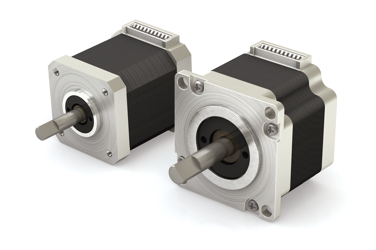
Motors SIMO Series

Integrated Stepper Motor
The driven SIMO Series systems are optimized for use with integrated stepper motors.
- 42 mm (NEMA 17)
- 56 mm (NEMA 23)
- Single, double, triple stack
- Performance specifications for each drive type:
- Lead screw
- Belt drive with horizontal motor mount
- Belt drive with vertical motor mount
- Ball screw – consult factory
- Standard wire connection is onboard plug
- Optional connections – consult factory
- Third party motor mount also available
Motor Lengths
| Motor Size | Single Stack | Double Stack | Triple Stack |
|---|---|---|---|
| 42 mm (NEMA 17) | 40 mm | 48 mm | 61 mm |
| 56 mm (NEMA 23) | 55 mm | 77 mm | 77 mm |
Note: Overall length calculations should include 7.8 mm width for motor mounting plate.
Top View

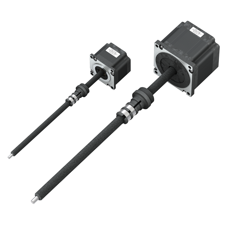
Integrated Hybrid Linear Actuator Setup
- Lead screw aligned and fixed directly with motor
- Fewer components
- Greater accuracy
- More reliable
- Higher rigidity
- Greater value
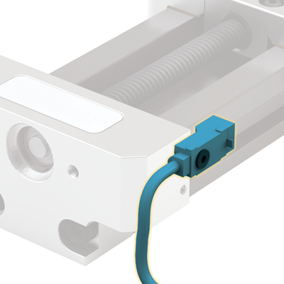
Onboard Connector Plug
Included with Integrated Motor Actuator


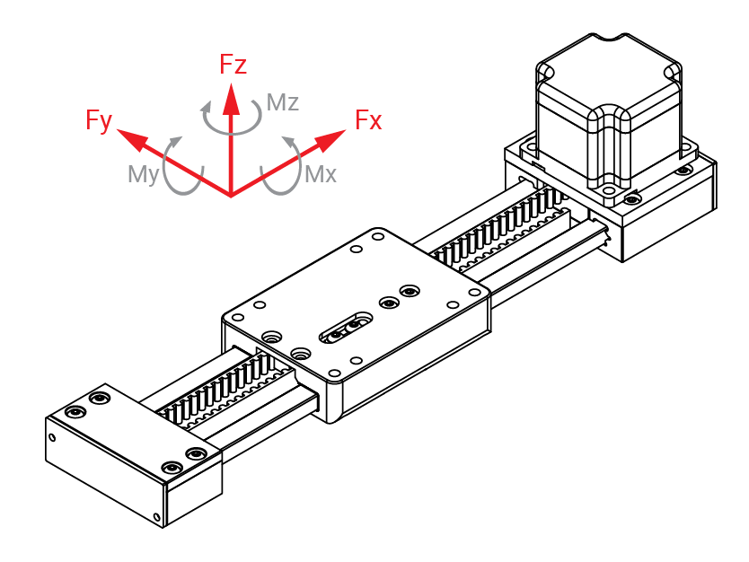
SIMO Series Load Calculations
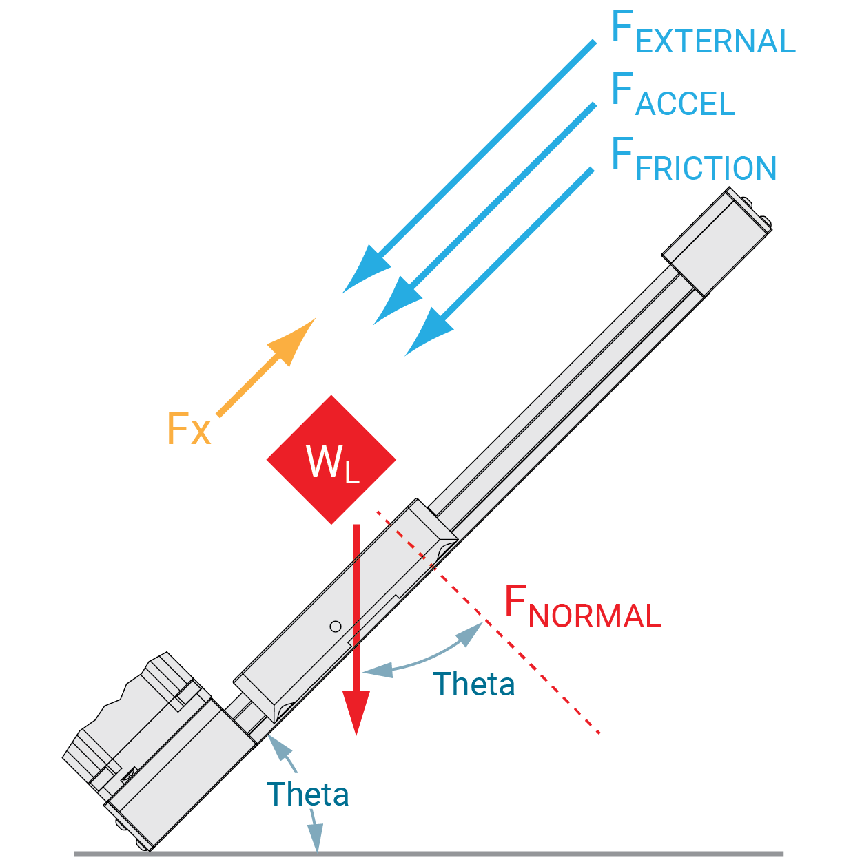
Use the formula below to verify acceptable loading conditions for your application.
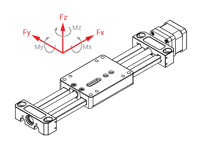
Calculation Factors:
- FZA and FYA are the radial and axial results of applied external forces in newtons (N)
- MXA, MYA, and MZA are the external moments being applied in newton-meters
- Fy, Fz, Mx, and Mz are the load ratings for various directions and moments
- Z is the relative safety factor as applied from the table below
Single Load Force Calculations
\( \displaystyle \frac{F_{ZA}}{F_Z} < \frac{1}{Z} \)
\( \displaystyle \frac{F_{YA}}{F_y} < \frac{1}{Z} \)
\( \displaystyle \frac{M_{XA}}{M_X} < \frac{1}{Z} \)
\( \displaystyle \frac{M_{YA}}{M_Y} < \frac{1}{Z} \)
\( \displaystyle \frac{M_{ZA}}{M_Z} < \frac{1}{Z} \)
Multiple Load Force Calculation
\( \displaystyle \frac{F_{ZA}}{F_Z} + \frac{F_{YA}}{F_y} + \frac{M_{XA}}{M_X} + \frac{M_{YA}}{M_Y} + \frac{M_{ZA}}{M_Z} < \frac{1}{Z} \)
Safety Factors
- Use the “Z” Safety Factor to adjust for dynamic forces and conditions particular to the application.
| Application Condition | Z Safety Factor |
|---|---|
| Consistently smooth motion with low frequency of travel reversal, slow speed (<30% MAX.), no shock load or vibration, no elastic yield or deformation, clean environment | 1.0 – 1.5 |
| Normal assembly or shop floor conditions, moderate speed (30% MAX. to 75% MAX.), normal shock or vibration conditions | 1.5 – 2.0 |
| Frequent reversal of travel, high speeds (>75% MAX.), shock loads and/or vibration present, high elastic yield or deformation, heavy dirt and dust in environment | 2.0 – 3.5 |
SIMO Series Accessories
Hand Knob
Hand adjustment knobs are used for manually adjusting screw driven systems
- Ideal for applications such as:
- Camera or sensor placement, conveyor guide adjustments, jig, fixture, or tool making applications, and more!

Hand Brake
Hand brakes are used to manually lock position in GST screw driven systems
- Ideal for holding position in applications such as:
- Label dispensing locations, bar code reader or sensor placements, pressure sensitive applications, and more!
Note: This is a friction brake (not a positive lock) and can be overcome if sufficient force is applied
Replacement Lubrication Kits
Used with CRT v-guide bearing systems
Part number: UGA040A-LHA-KIT
(2) Lube Holder Asy RRC034 molded/hinged
(4) BHSCS M3 x 0.5 x 8 mm long
Used with GST plain bearing systems
Part number: UGA040A-JKM-KIT
(2) Felt Strip F1 0.375 x 0.094 'k'
(2) JKM Plate, UGA040
(4) SFHCS M3 x 0.5 x 8 mm long

Sensor Mounting
Sensor brackets accommodate a variety of sensor types
- End of travel / overtravel sensors
- Slot type sensors
- Proximity switches
- Consult factory for options
Rail Mount Sensor Bracket Kit
Part Number: LATA-SENBRKT-KIT
Adjustable mounting bracket for use
with proximity sensors intended to
be installed under carriage. Insert
17 supplied t-nut into slot on rail. Use supplied M5 fastener to mount sensor bracket. See below for M3 Flag Fastener and/or M4 Square Nut
placement.

Kit Contains:
1. (1) Slot Mount Sensor Bracket
2. (1) M5 Bracket Mount Fastener
3. (1) M5 Bracket T-Nut
4. (1) M2.5 Sensor Mount Fastener
5. (1) M3 Flag Fastener
6. (1) M4 Square Nut (Spacer)
For use with these Proximity Sensors
6201038 - Inductive Prox. Sensor, PNP, NC
6201039 - Inductive Prox. Sensor, PNP, NO
6201040 - Inductive Prox. Sensor, NPN, NO

Cam Roller V-Guide Carriage
On the underside of carriage, replace existing low profile wiper fastener with supplied M3 fastener. The supplied M3 fastener will be used to flag the sensor. Any of the (4) existing wiper fasteners can be replaced with the supplied M3 fastener depending on application requirements.

Gliding Surface Carriage
On the underside of carriage with no lube option, install supplied square nut and M3 fastener. The supplied M3 fastener (combined with square nut) will be used to flag the sensor. Any of the (4) existing holes can be used depending on application requirements.

Inductive Proximity Sensor Switches
Home sensor or position sensor with rectangular shape and only 11 mm width. DC 3-wire (10-30V DC)
6200418 Sensor, NPN, NO, 6200699 Sensor, PNP, NO
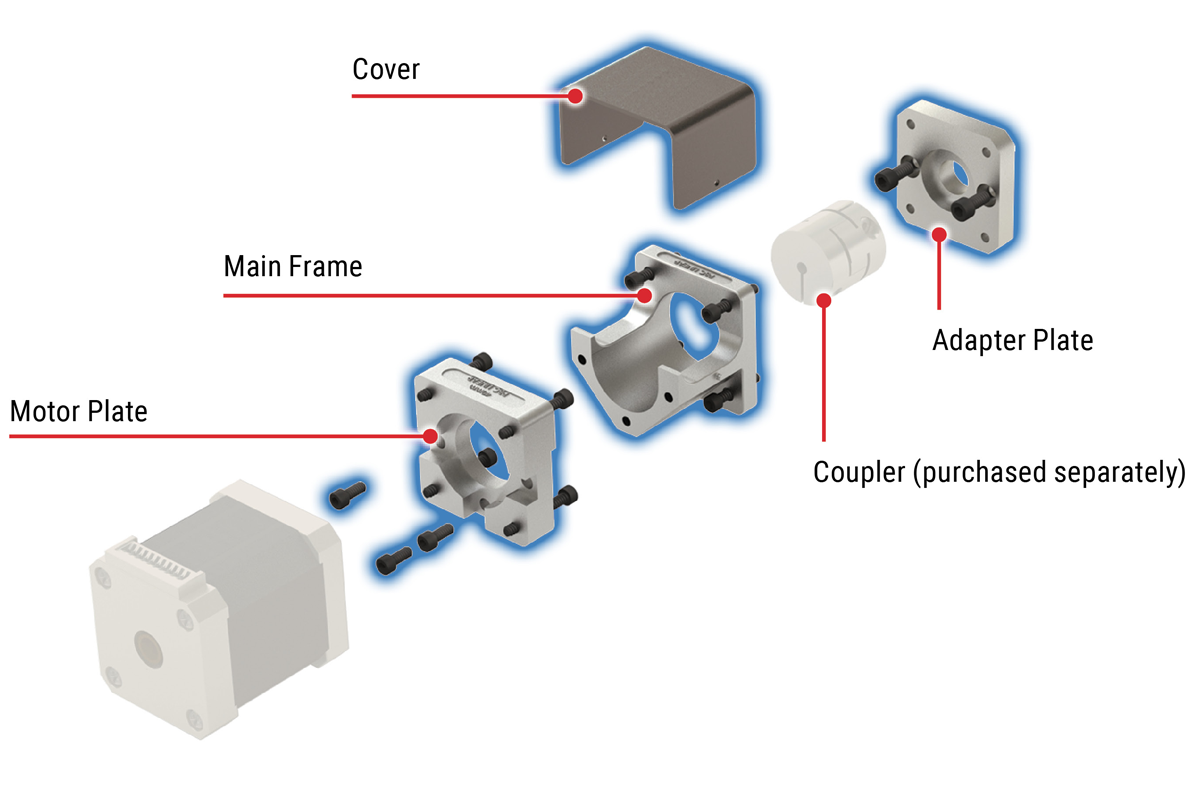
Motor Mount
Motor mount option for attaching a stepper, servo, or smart motor, etc.
- One-piece main frame holds shaft-to-shaft centerline
- Easily attach with adapter plate and coupler
- Consult a PBC Linear Application Engineer about mounting options for other types of motor and coupler arrangements

System Covers
Covers help keep raceways clear of debris and contamination
- Consult a PBC Linear Application Engineer regarding your specific application to provide protection from corrosive elements in the application environment
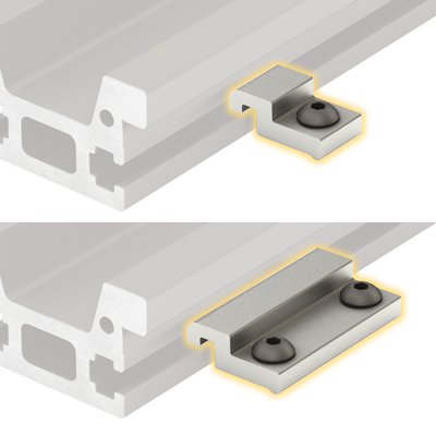
T-Nuts
Roll in t-nut for 5 mm slot with M5 tap. PBC Linear part number 6100443.

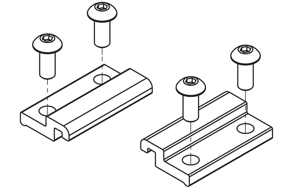
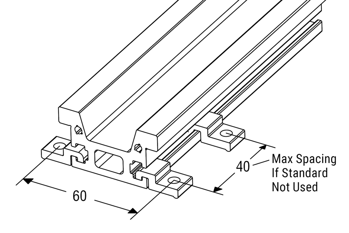
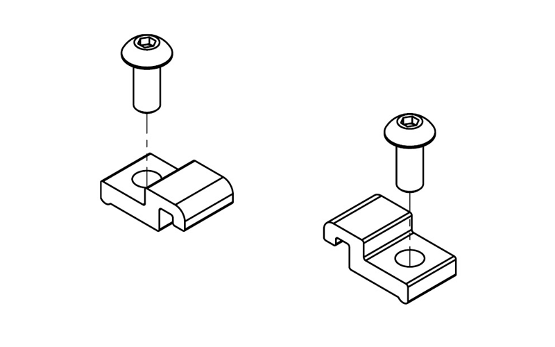
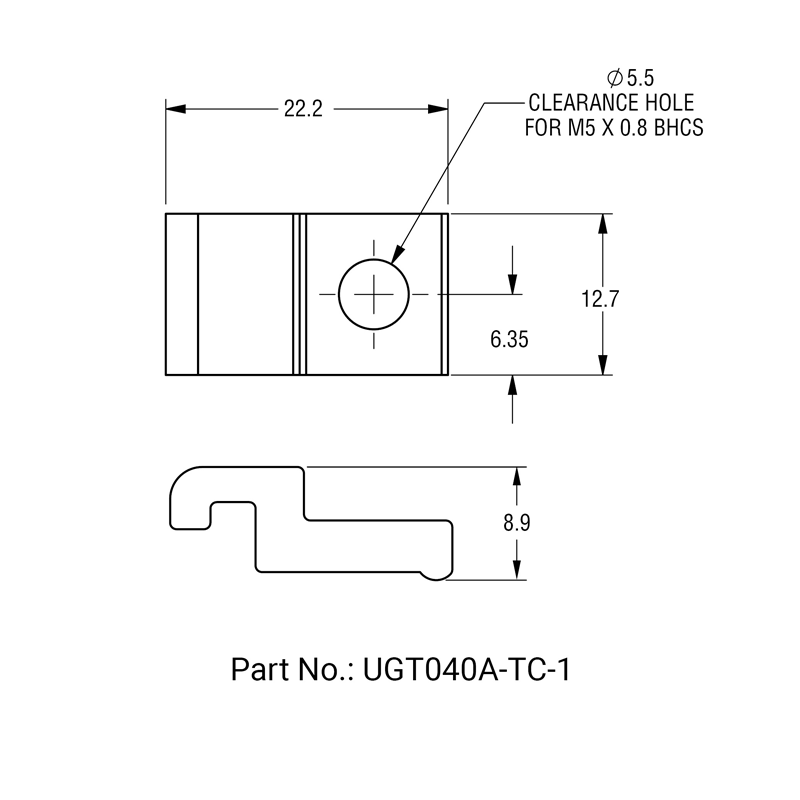
Small Toe Clamp
Part Number: UGT040A-TC-1
Small toe clamps are used to secure the (UGT) tall rail to the mounting surface
- Mounted with one M5 x 0.8 BHCS (not included)
- 40 mm max spacing between clamps
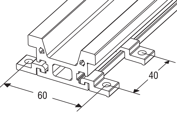
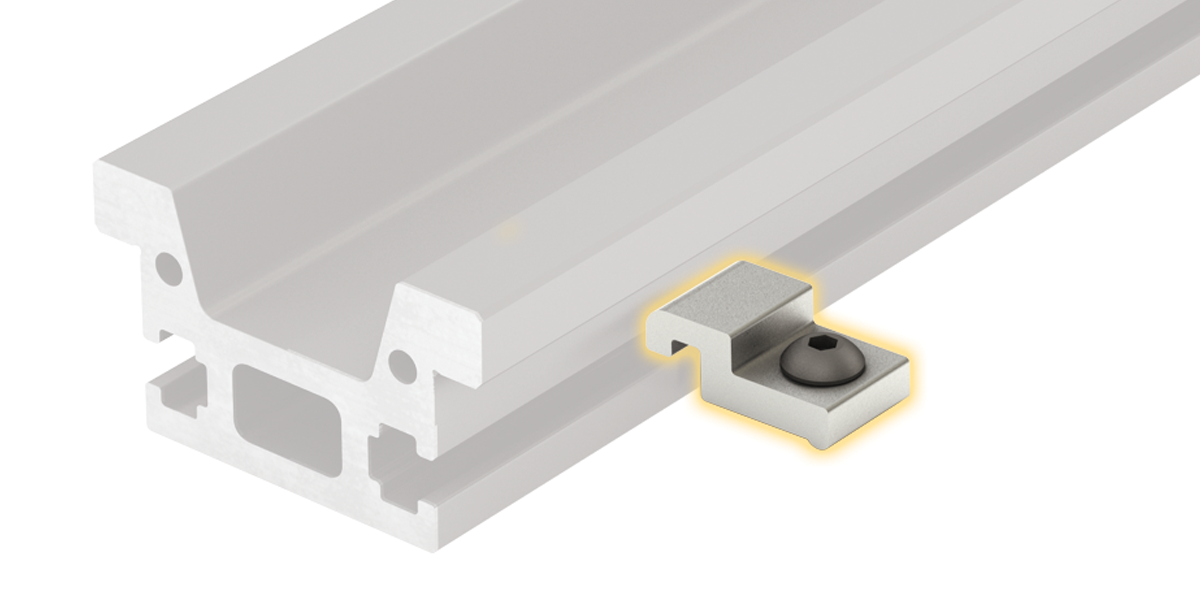
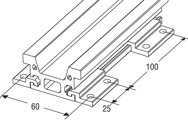
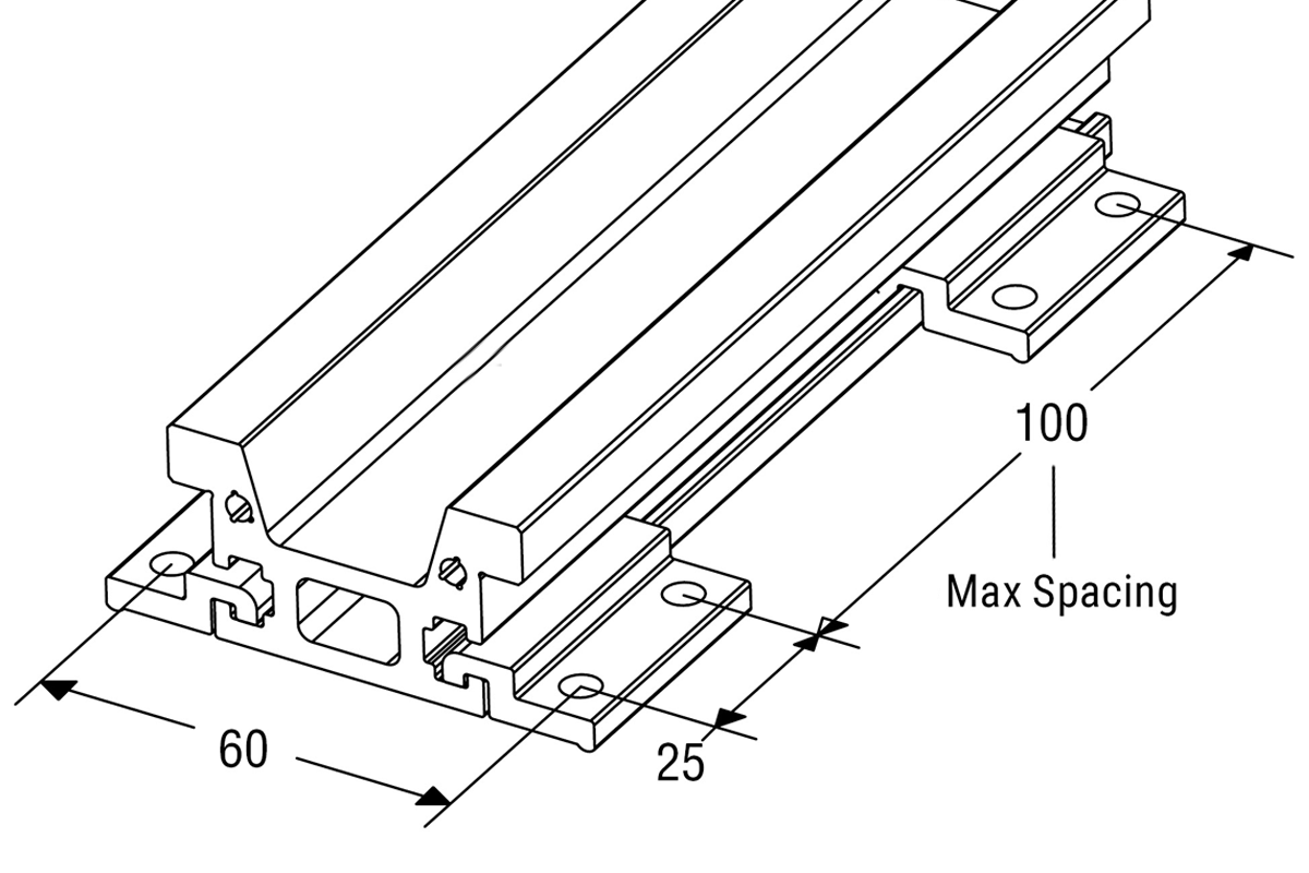
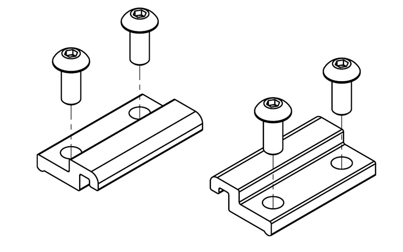
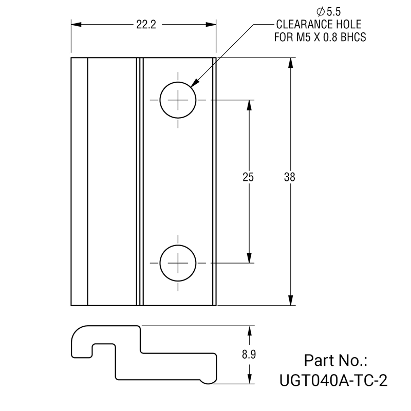
Large Toe Clamp
Part Number: UGT040A-TC-2
Large toe clamps are used to secure the (UGT) tall rail to the mounting surface
- Mounted with two M5 x 0.8 BHCS (not included)
- 100 mm max spacing between clamps
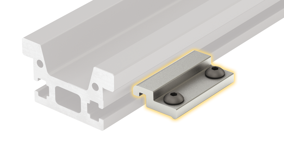
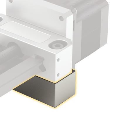
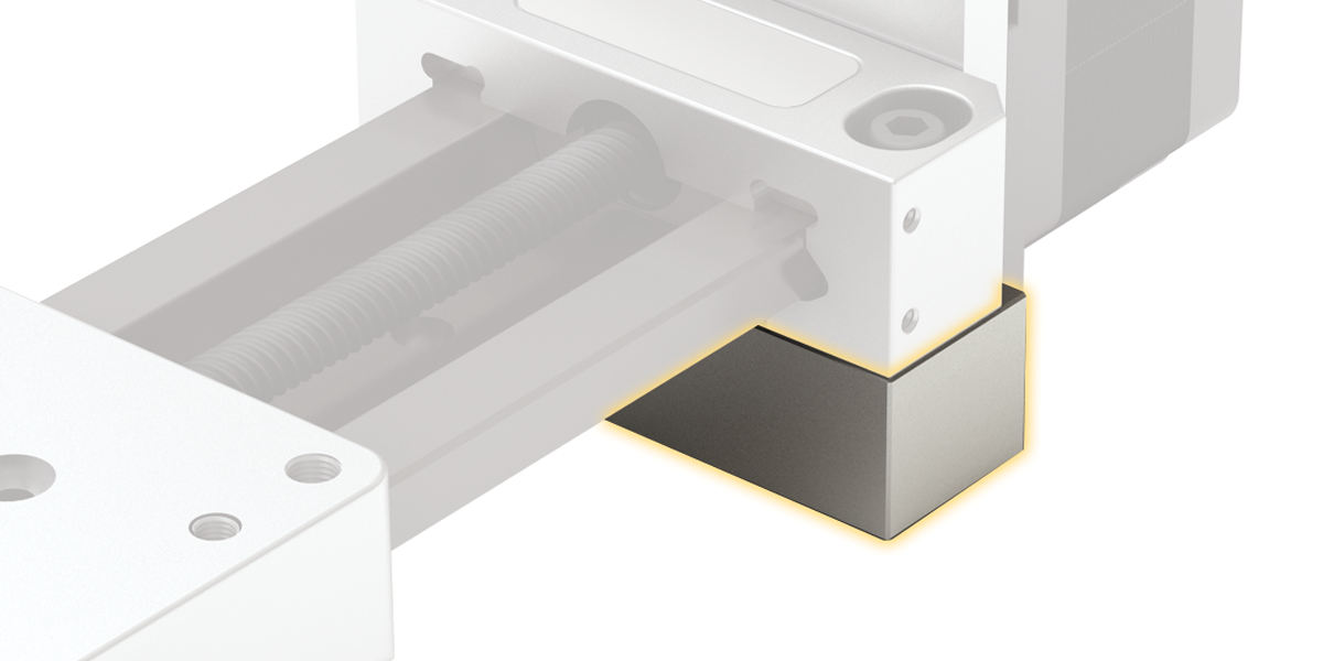
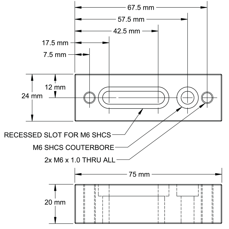
Riser Block
Riser blocks provide clearance for the motor when using the (UGA) low profile rail
Part Numbers:
UGA040A-RSRPLT-10 42 mm (Nema 17)
UGA040A-RSRPLT-20 56 mm (Nema 23)
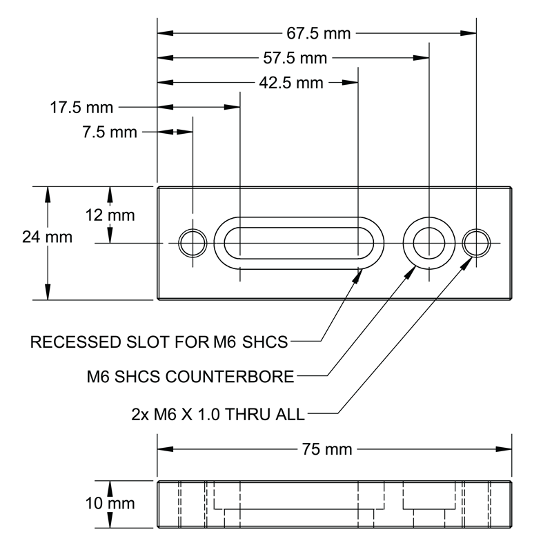
10 mm Height Riser Block Dimensions
Typically used with 42 mm (NEMA 17) motor
20 mm Height Riser Block Dimensions
Typically used with 56 mm (NEMA 23) motor
Multi-Axis Systems Mounting Plates

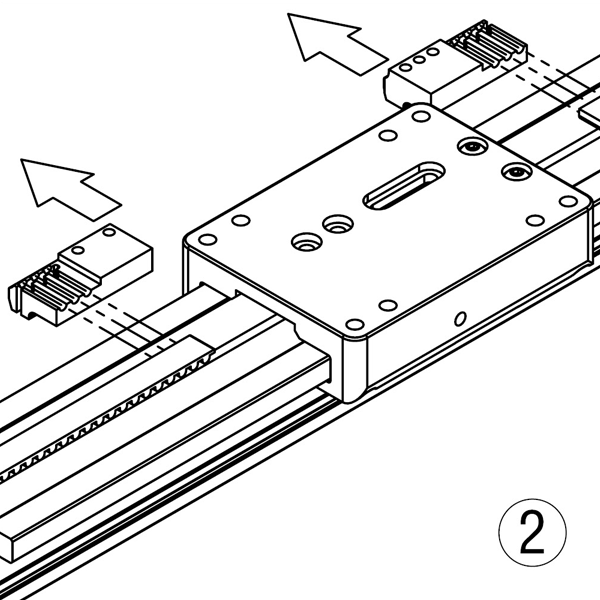
Option 1 Carriage-To-Carriage Mounting
Design multi-axis systems easily with the versatile carriage to carriage mounting plate.
- Attach any combination of SIMO Series bearing type – GST, CRT, PRT
- Units may be comprised of either UGA (low profile) and/or UGT (tall) rails
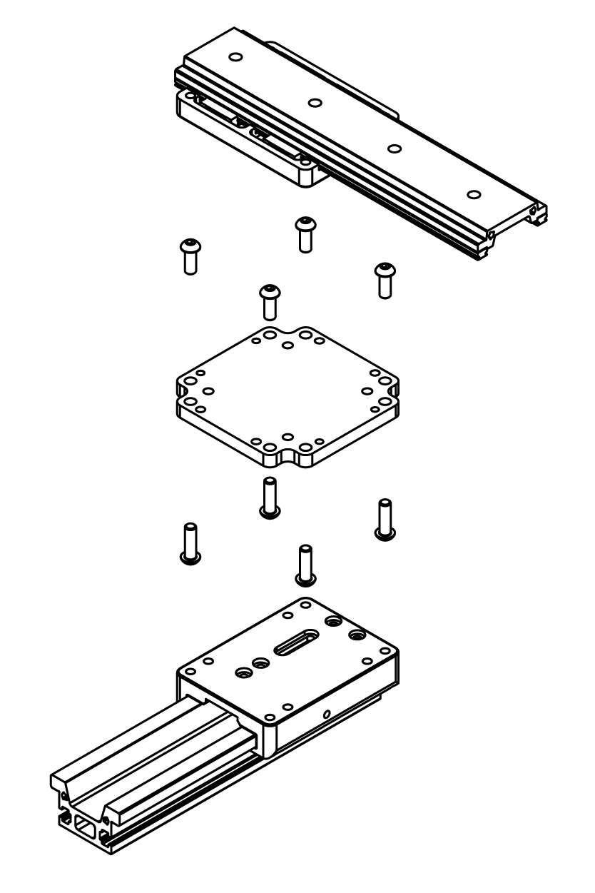
Easy step-by-step mounting process:
Step 1: Attach mounting plate to the base carriage
Step 2: Fasten screws (PBC Linear recommends using a low strength thread locker)
Step 3: Attach top carriage
Step 4: Fasten screws (PBC Linear recommends using a low strength thread locker)
Carriage-To-Carriage
Mounting Plate Specifications
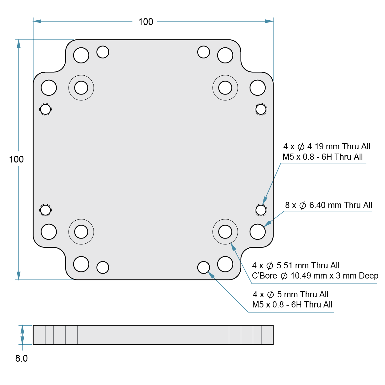
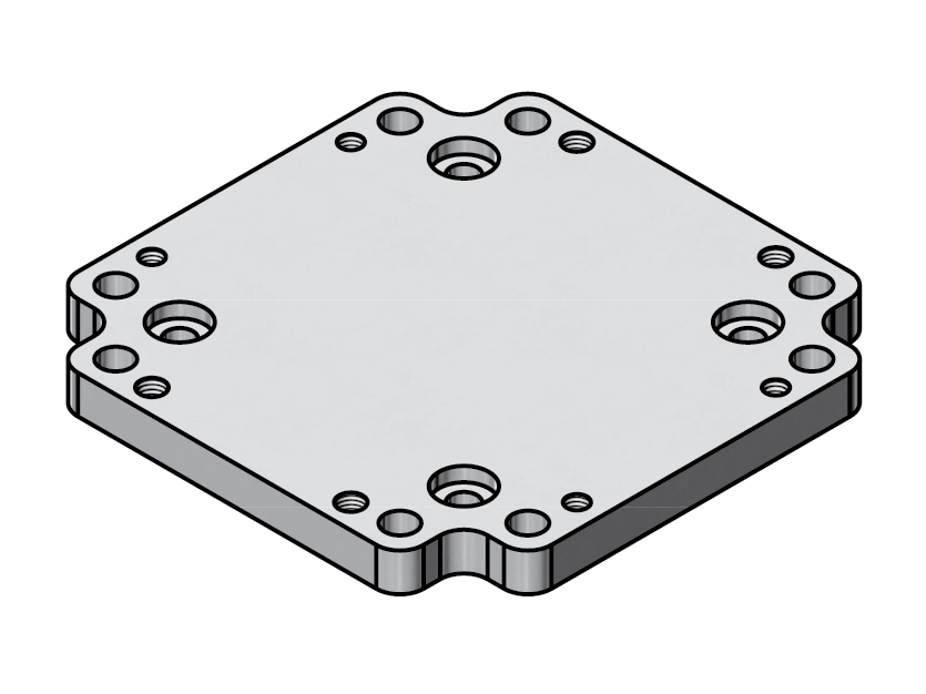
Plate A

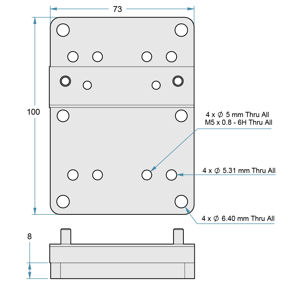
Option 2 Carriage-To-Rail Mounting
Design complex multi-axis systems easily with the carriage to rail mounting plate.
Easy step-by-step mounting process:
Note: For GST & CRT base-mounted assemblies (Kit #5), attach the top rail to the base carriage using toe clamps – no bracket is necessary. For sidemounted assemblies (Kit #6), attach plate B2 to plate B1, and position t-nuts in rail prior to the following steps
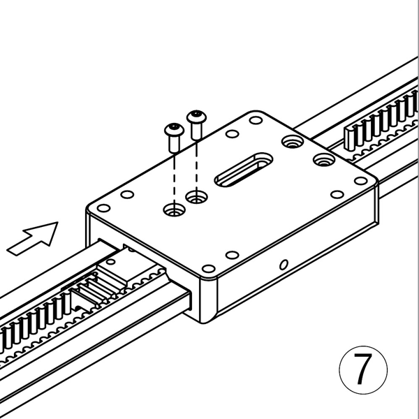
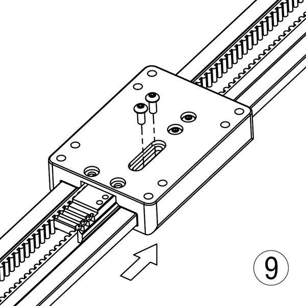
Step 1: Attach mounting plate to the base carriage
Step 2: Fasten screws (PBC Linear recommends using a low strength thread locker)
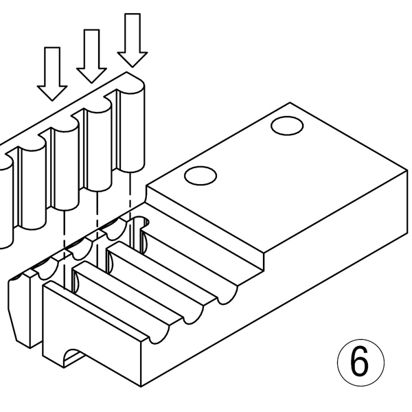
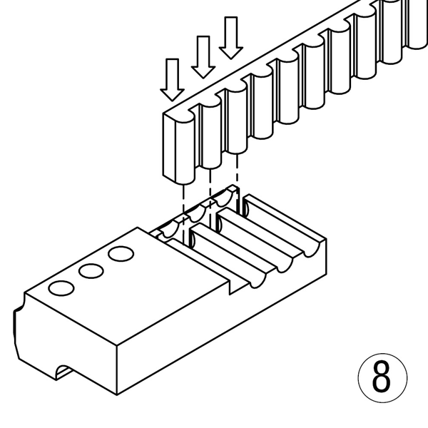
Step 3: Attach top rail, either with t-nuts (Kit #6), toe clamps (Kit#7), or by using the holes in the top rail (Kit #8).
Step 4: Fasten screws (PBC Linear recommends using a low strength thread locker)
Carriage-To-Rail
Mounting Plate Specifications


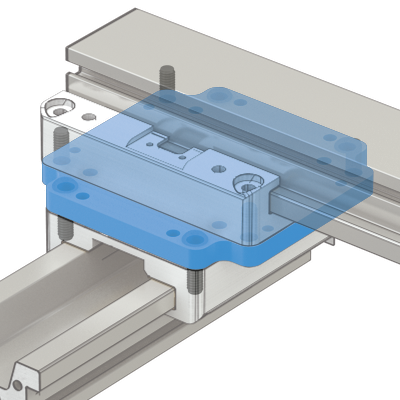
Option 1 Carriage-To-Carriage Mounting
Connect any combination of UGA (low profile) and UGT (tall) rails using the carriage-to-carriage mounting plate.
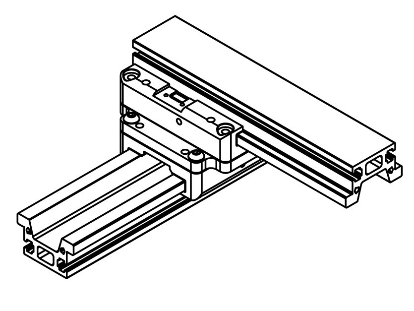
Two UGT (tall) rails connected
with the carriage mounting plate.
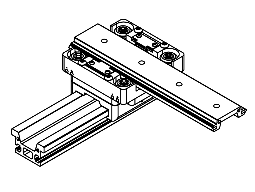
A combination–one UGT (tall) and one UGA (low profile) rail attached with the carriage mounting plate.
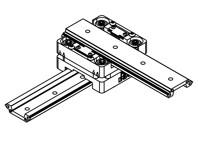
Two UGA (low profile) rails connected with the carriage mounting plate.
Kit #1:
GST to GST
Kit #2:
GST to CRT
CRT to GST
Kit #3:
CRT to CRT


Carriage-To-Carriage Mounting
Ordering Information
| Base System | Attached To | Parts Included in Kit | Qty | Kit Part Number | |
|---|---|---|---|---|---|
| 1 | GST | GST | Plate A (carriage-to-carriage) BHSCS M6 x 20 |
1 8 |
LATA-KIT-038 |
| 2 | GST | CRT | Plate A (carriage-to-carriage) BHSCS M5 x 16 BHSCS M5 x 30 |
1 4 4 |
LATA-KIT-039 |
| CRT | GST | ||||
| 3 | CRT | CRT | Plate A (carriage-to-carriage) BHSCS M5 x 30 |
1 8 |
LATA-KIT-041 |
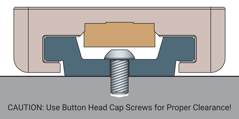
Note: GST = Gliding Surface Technology–Plain Bearings, CRT = Cam Roller Technology–V-Guide Bearings, UGA = Low profile rail, UGT = Tall rail. The carriage-to-carriage mounting plate has counterbores on one side to allow for flush mounting.
Option 2 Carriage-To-Rail Mounting
Rails can be mounted via side mount or base mount depending on the application requirements.
Side Mount

Base Mount
Kit #4:
GST to UGT Rail
CRT to UGT Rail
* Base mount with toe clamps
Kit #5:
GST to UGT Rail
CRT to UGT Rail
* Side mount with t-nuts
Kit #6:
GST to UGA Rail
CRT to UGA Rail
* Base mount with screws
** Not designed for lead screw driven systems


Carriage-To-Rail Mounting
Ordering Information
| Base System (UGA or UGT) | Attached To Rail Type | Mount Type | Parts Included in Kit | Qty | Kit Part Number | |
|---|---|---|---|---|---|---|
| 4 | GST CRT |
UGT | Base | Small Toe Clamp BHSCS M5 x 16 (4) |
4 4 |
LATA-KIT-042 |
| 5 | GST CRT |
UGT | Side | Plate B1 (carriage-to-rail) Plate B2 (carriage-to-rail) BHSCS M6 x 16 (4) SHCS M5 x 12 T-Nuts M5 BHSCS M5 X 16 (4) |
1 1 4 2 2 |
LATA-KIT-043 |
| 6 | GST CRT |
UGA | Base | Plate B1 (carriage-to-rail) BHSCS M6 x 16 (4) BHSCS M6 x 12 BHSCS M5 X 16 (4) |
1 4 2 |
LATA-KIT-045 |
Note: GST = Gliding Surface Technology–Plain Bearings, CRT = Cam Roller Technology–V-Guide Bearings, UGA = Low profile rail, UGT = Tall rail.
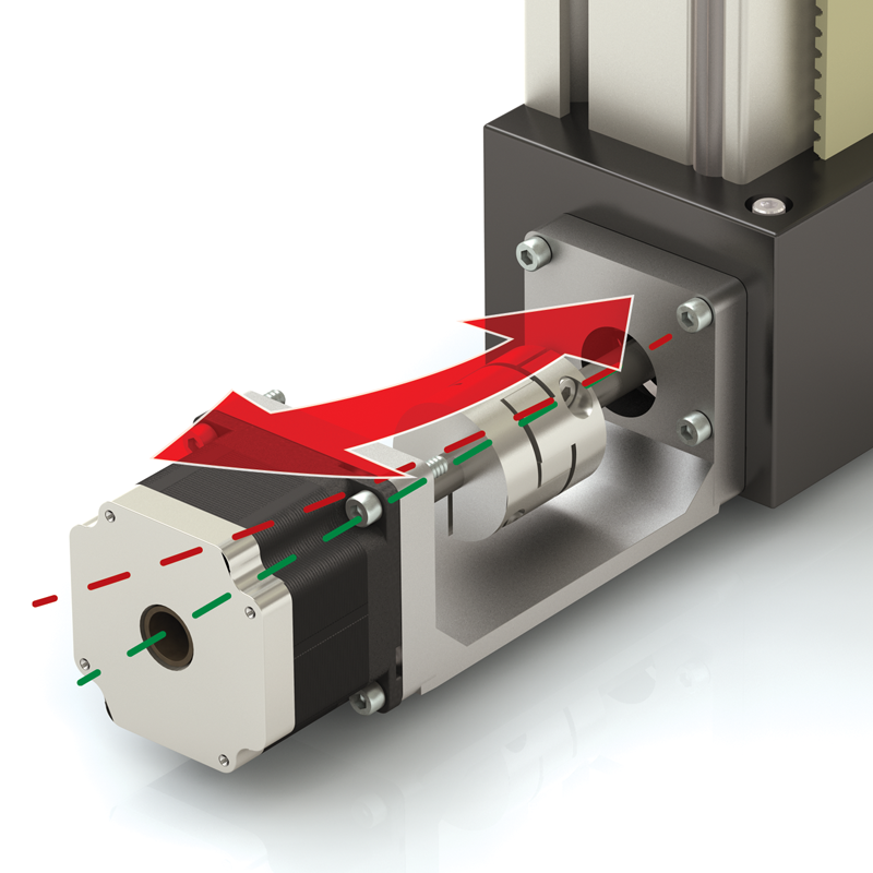
Motor Mount Product Comparison
PBC Linear Design vs. Alternate Designs
PBC Linear Design with Pre-Engineered Alignment
- One-piece main frame holds shaft-to-shaft centerline
- Extends motor and coupler life
- Increases accuracy and repeatability
- Easy to assemble
Problematic Designs Cause Misalignment
- Misalignment between motor shaft, coupler, and screw shortens life and affects motion quality
- Misalignment results in camming or lobbing motion that translates to inconsistent linear movement
- Difficult to align and prone to deflection
- Over-torque of coupler causes accuracy loss
⚠ CAUTION
Problem #1
Deflection
Problem #2
Twist
Problem #3
Off Centerline


Lead Screw or Ball Screw
Driven System
Screw Driven SIMO Series System
Lead Screw or Ball Screw
UGA (Low Profile) or UGT (tall profile)
| Motor Size |
Part Number |
Recommended Coupler Ordered Separately or Customer Supplied |
Included with Motor Mount Purchase |
|---|---|---|---|
| 40 mm | UGA040A-3PMM-SE | R + W EKL5 Maximum coupler dimensions: 25 mm O.D. x 26 mm length |
(1) Adapter plate with 2 SBHCS (Socket Button Head Cap Screw) (1) Main frame with 4 SBHCS (1) Motor plate with 3 SBHCS for attaching to frame* (1) Cover (plastic) * Customer supplies motor screws |
| 42 mm NEMA 17 |
UGA040A-3PMM-SF | ||
| 56 mm - 58 mm NEMA 23 |
UGA040A-3PMM-SG | ||
| 60 mm | UGA040A-3PMM-SH | ||
| Blank Plate (customer machined) |
UGA040A-3PMM-S0 |
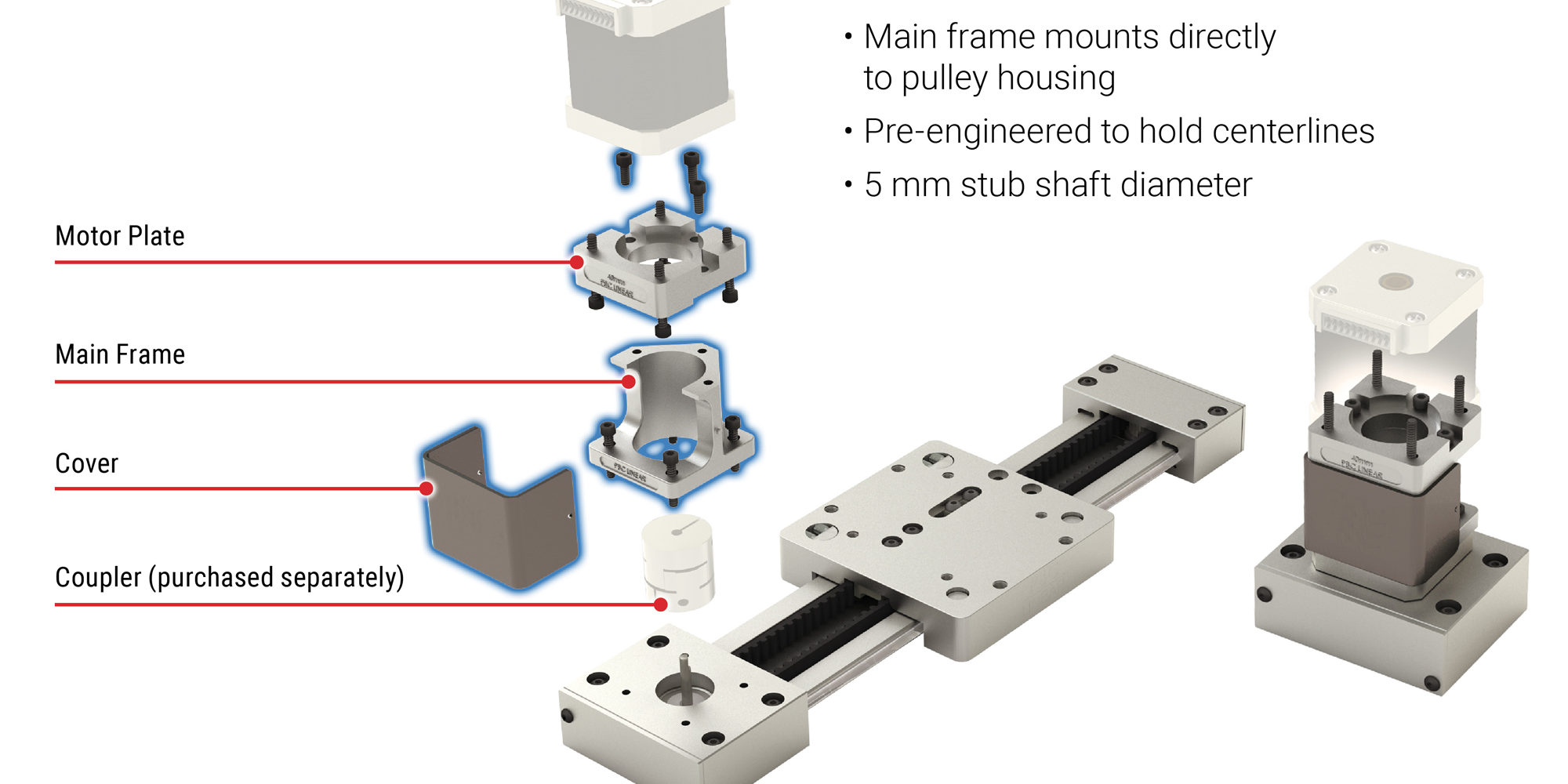
- Pre-engineered to hold centerlines
- 5 mm stub shaft diameter
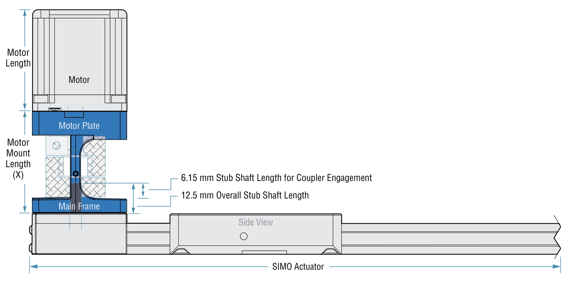
Motor Mount Length
| Motor Mount Length (X) | |||||
|---|---|---|---|---|---|
| Type of SIMO System |
Motor Size | ||||
| 40 mm | 42 mm (NEMA 17) |
56 mm - 58 mm (NEMA 23) |
60 mm | ||
| Screw Driven |
mm | 54.0 | 53.7 | 54.3 | 59.0 |
| inches | 2.125 | 2.115 | 2.139 | 2.322 | |

Horizontal Belt Driven System
Belt Driven SIMO Series System
Horizontal Belt
UGT Tall Profile
| Motor Size | Part Number | Recommended Coupler Ordered Separately or Customer Supplied |
Included with Motor Mount Purchase |
|---|---|---|---|
| 40 mm | UGA040A-3PMM-HE | R + W EKL5 Maximum coupler dimensions: 25 mm O.D. x 26 mm length |
(1) Main frame with 4 SBHCS (Socket Button Head Cap Screw) (1) Motor plate with 3 SBHCS for attaching to frame* (1) Cover (plastic) * Customer supplies motor screws |
| 42 mm NEMA 17 |
UGA040A-3PMM-HF | ||
| 56 mm - 58 mm NEMA 23 |
UGA040A-3PMM-HG | ||
| 60 mm | UGA040A-3PMM-HH | ||
| Blank Plate (customer machined) |
UGA040A-3PMM-H0 |
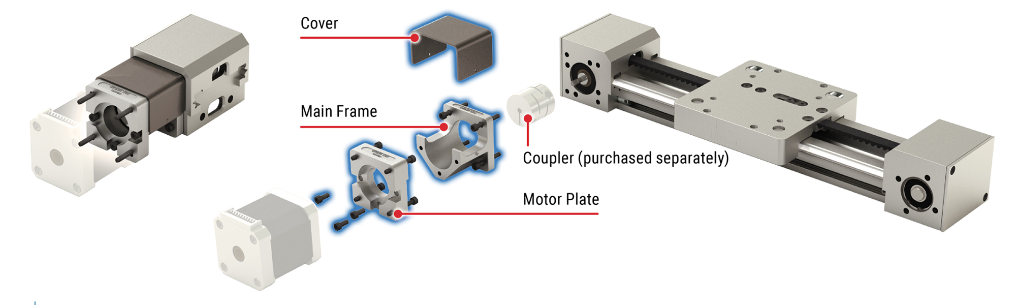

- Main frame mounts directly to pulley housing
- Pre-engineered to hold centerlines
- 10 mm stub shaft diameter
Motor Mount Length
| X | |||||
|---|---|---|---|---|---|
| Type of SIMO System |
Motor Size | ||||
| 40 mm | 42 mm (NEMA 17) |
56 mm - 58 mm (NEMA 23) |
60 mm | ||
| Screw Driven |
mm | 46.2 | 45.9 | 46.5 | 51.2 |
| inches | 1.817 | 1.807 | 1.831 | 2.014 | |
Vertical Belt Driven System

Belt Driven SIMO Series System
Vertical Belt
UGA Low Profile
| Motor Size | Part Number | Recommended Coupler Ordered Separately or Customer Supplied |
Included with Motor Mount Purchase |
|---|---|---|---|
| 40 mm | UGA040A-3PMM-VE | R + W EKL5 Maximum coupler dimensions: 25 mm O.D. x 26 mm length |
(1) Main frame with 4 SBHCS (Socket Button Head Cap Screw) (1) Motor plate with 3 SBHCS for attaching to frame* (1) Cover (plastic) * Customer supplies motor screws |
| 42 mm NEMA 17 |
UGA040A-3PMM-VF | ||
| 56 mm - 58 mm NEMA 23 |
UGA040A-3PMM-VG | ||
| 60 mm | UGA040A-3PMM-VH | ||
| Blank Plate (customer machined) |
UGA040A-3PMM-V0 |
Motor Mount Length
| X | |||||
|---|---|---|---|---|---|
| Type of SIMO System |
Motor Size | ||||
| 40 mm | 42 mm (NEMA 17) |
56 mm - 58 mm (NEMA 23) |
60 mm | ||
| Screw Driven |
mm | 46.2 | 45.9 | 46.5 | 51.2 |
| inches | 1.817 | 1.807 | 1.831 | 2.014 | |
Motor Plate Dimensions
Motor Size: 40 mm
- Material: Anodized aluminum

Motor Size: 42 mm (NEMA 17)
- Material: Anodized aluminum

Motor Size: 56 mm – 58 mm (NEMA 23)
- Material: Anodized aluminum

Motor Size: 60 mm
- Material: Anodized aluminum

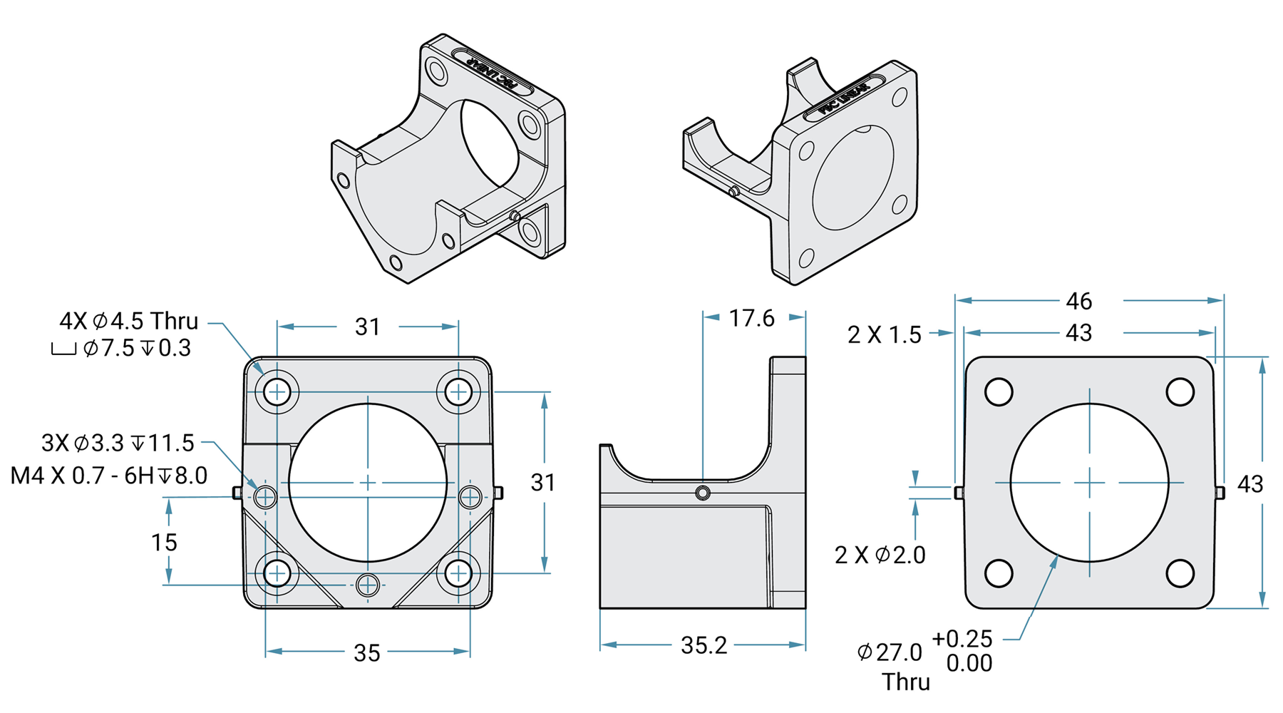
Blank Plate & Main Frame Dimensions
Blank Plate
- Intended use: To give customers the ability to machine the plate to match non-standard motor configurations
- Material: Anodized aluminum
- Tip: It is best to clamp on center hole when machining hole pattern for motor attachment.

Main Frame
- Material: Die cast aluminum, clear chromate
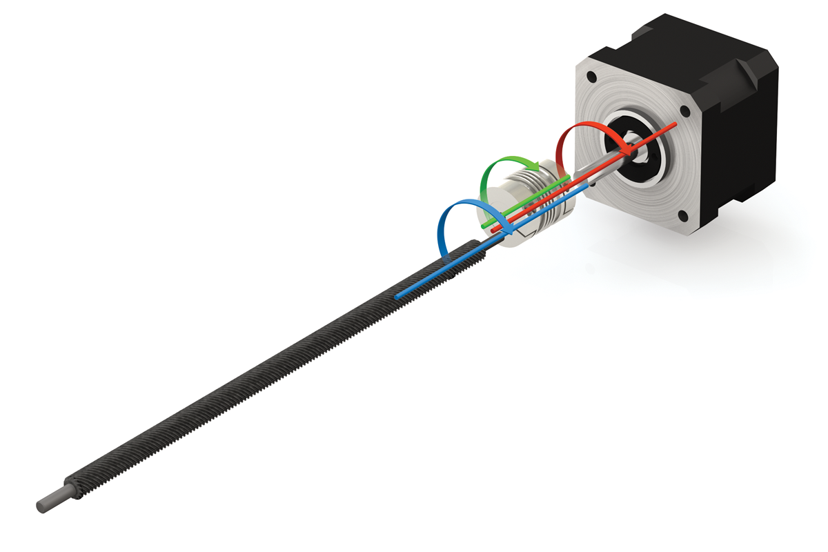
Design Considerations
Coupler
- Simo Series motor mounts are designed to work optimally with the R+W EKL5 coupler
- Other couplers can be used under the following conditions:
- Maximum O.D. = 25 mm
- Maximum length = 26 mm
- Coupler should be sized per the SIMO Series actuator.
⚠ CAUTION
Verify coupler bore diameters and depths will accept both actuator stub shaft and motor shaft.

Stub Shaft Dimensions
| Type of SIMO System | Screw Driven | Horizontal Belt | Vertical Belt |
|---|---|---|---|
| Stub Shaft Diameter | 5 mm | 10 mm | 5 mm |
| Overall Stub Shaft Length | 21.6 mm | 12.5 mm | 12.5 mm |
| Stub Shaft Length for Coupler Engagement |
7.427 mm | 6.15 mm | 6.15 mm |
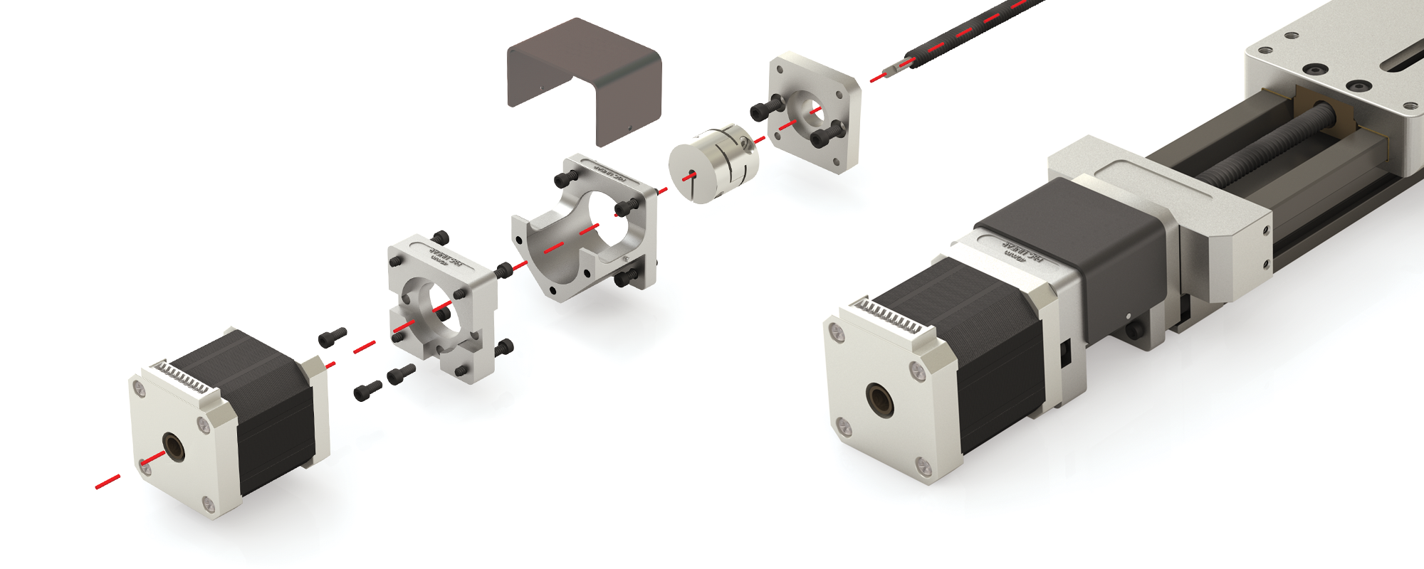
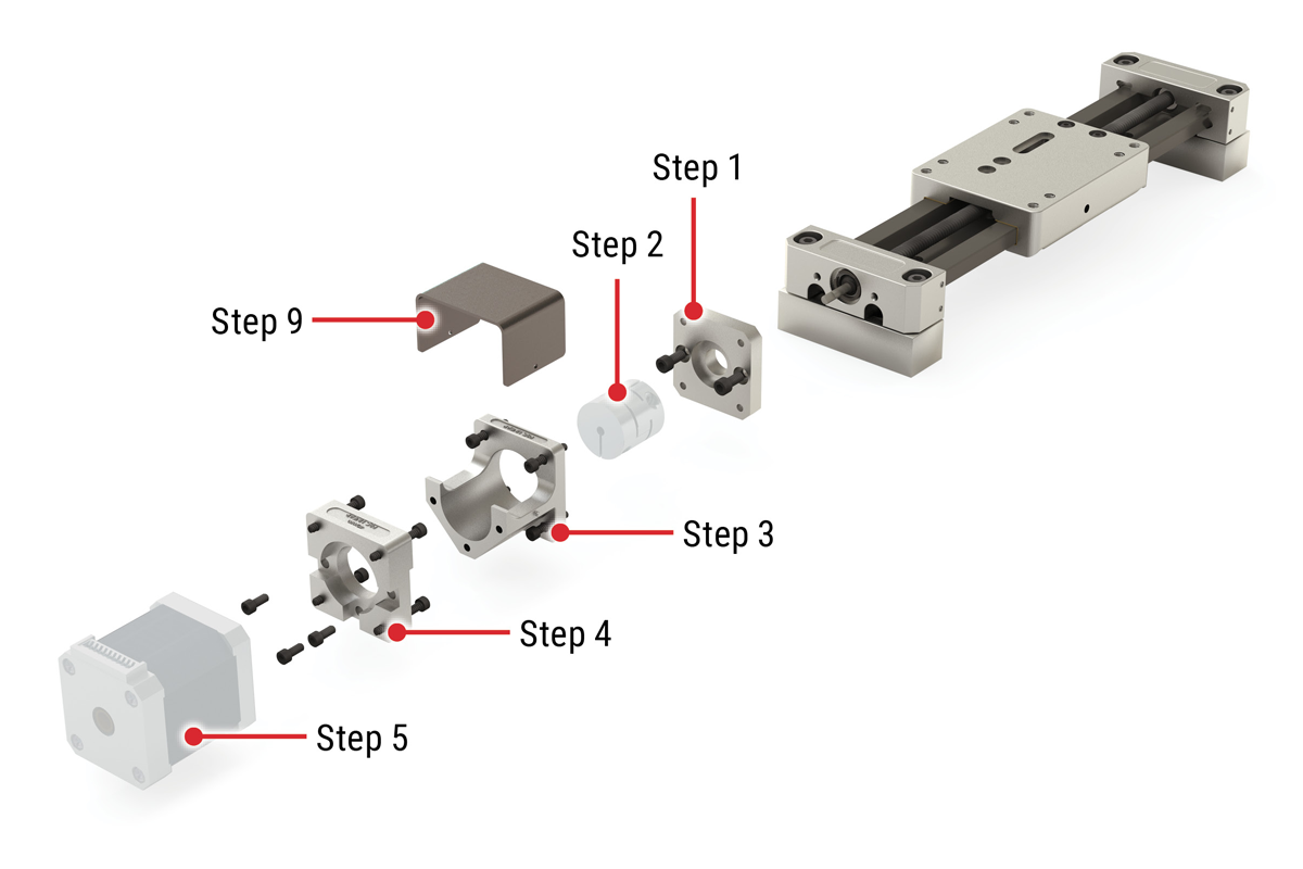
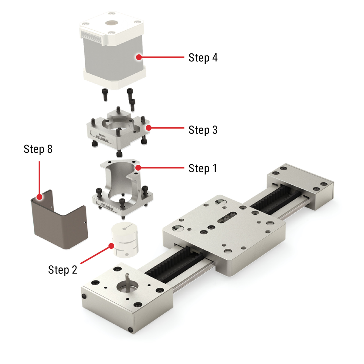
Assembly Procedure
Screw Driven System
SIMO Series UGA/UGT with Lead Screw
Components:
- Base actuator unit
- Motor (customer supplied)
- Motor Mount Kit
- Adapter Plate
- Motor Plate
- Main Frame
- Cover
- Coupler (customer supplied)
Fasteners: (9) M4 x 12 mm SBHCS (supplied by PBC Linear),
(4) Customer supplied motor fasteners (See Table 2)
Tools Required: Hex Key (See Table 1)
Suggested Thread Locker: Blue Loctite® 242 or equivalent
Table 1
Table 2
Table 3
Simo Series – UGA (Low Profile)
Simo Series – UGT (Tall Profile)
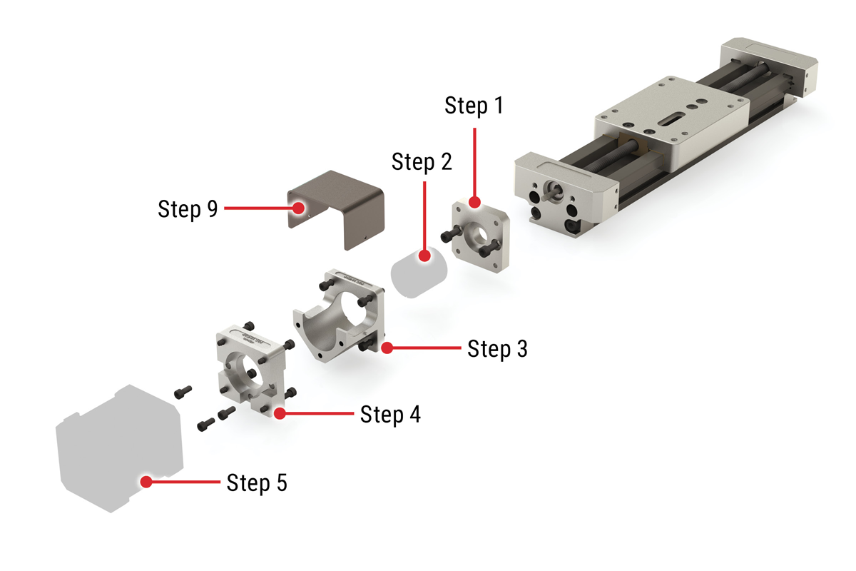
Assembly Steps
- Install lead screw adapter plate to actuator end cap using hex key and (2) M4 x 12 mm SBHCS. Apply blue Loctite® 242 or equivalent threadlocker and torque to 17-21 in/lb [2.0-2.4 Nm] (See Table 3).
- Slide coupling onto shaft and leave loose.
- Install main frame to lead screw adapter plate using (4) M4 x 12 mm SBHCS. Snug fasteners, but do not tighten.
- Install motor plate to main frame using (3) M4 x 12 mm SBHCS. Apply blue Loctite® 242 or equivalent threadlocker and torque to 17-21 in/lb [2.0-2.4 Nm] (See Table 3).
- Install motor to motor plate with customer supplied fasteners (See Table 2) and install shaft into coupling. Snug fasteners, but do not tighten.
- Manually move carriage plate to align coupler and motor.
- Check for proper shaft engagement on both sides (per coupler manufacturer specs).
- Once system is aligned, final torque all fasteners appropriately (See Table 3).
- Install cover on pins in casting (snaps in place).
Horizontal Belt Driven System
Simo Series UGT with Horizontal Belt
Components:
- Base actuator unit
- Motor (customer supplied)
- Motor Mount Kit
- Motor Plate
- Main Frame
- Cover
- Coupler (customer supplied)
Fasteners: (7) M4 x 12 mm SBHCS (supplied by PBC Linear), (4) Customer supplied motor fasteners (See Table 2)
Tools Required: Hex Key (See Table 1)
Suggested Thread Locker: Blue Loctite® 242 or equivalent
Table 1
Table 2
Table 3
Simo Series – UGT (Tall Profile)
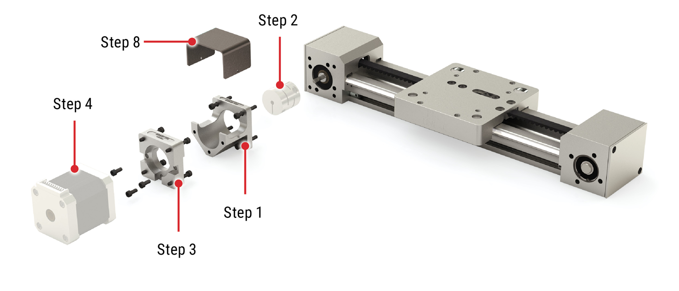
Assembly Steps
- Install main frame to pulley housing using hex key and (4) M4 x 12 mm SBHCS. Snug fasteners, but do not tighten.
- Slide coupling onto shaft and leave loose.
- Install motor plate to main frame using (3) M4 x 12 mm SBHCS. Apply blue Loctite® 242 or equivalent threadlocker and torque to 17-21 in/lb [2.0-2.4 Nm] (See Table 3).
- Install motor to motor plate with customer supplied fasteners (See Table 2) and install shaft into coupling. Snug fasteners, but do not tighten.
- Manually move carriage plate to align coupler and motor.
- Check for proper shaft engagement on both sides (per coupler manufacturer specs).
- Once system is aligned, final torque all fasteners appropriately (See Table 3).
- Install cover on pins in casting (snaps in place).
Vertical Belt Driven System
Simo Series UGA with Vertical Belt
Components:
- Base actuator unit
- Motor (customer supplied)
- Motor Mount Kit
- Motor Plate
- Main Frame
- Cover
- Coupler (customer supplied)
Fasteners: (7) M4 x 12 mm SBHCS (supplied by PBC Linear), (4) Customer supplied motor fasteners (See Table 2)
Tools Required: Hex Key (See Table 1)
Suggested Thread Locker: Blue Loctite® 242 or equivalent
Table 1
Table 2
Table 3
Simo Series – UGA (Low Profile)
Assembly Steps
- Install main frame to pulley housing using hex key and (4) M4 x 12 mm SBHCS. Snug fasteners, but do not tighten.
- Slide coupling onto shaft and leave loose.
- Install motor plate to main frame using (3) M4 x 12 mm SBHCS. Apply blue Loctite® 242 or equivalent threadlocker and torque to 17-21 in/lb [2.0-2.4 Nm] (See Table 3).
- Install motor to motor plate with customer supplied fasteners (See Table 2) and install shaft into coupling. Snug fasteners, but do not tighten.
- Manually move carriage plate to align coupler and motor.
- Check for proper shaft engagement on both sides (per coupler manufacturer specs).
- Once system is aligned, final torque all fasteners appropriately (See Table 3).
- Install cover on pins in casting (snaps in place).
User Manual
Tips for Safe Installation and Operation
- Only qualified personnel should transport, assemble, operate, and maintain this equipment.
- Always wear appropriate personal protection equipment, such as safety glasses and hearing protection.
- Read and observe the installation, operating, and safety instructions provided by the manufacturer. Incorrect handling and operation may result in damage to equipment and personal injury.
- Comply with all installation specifications and requirements to ensure proper setup.
- Provide a flat and stable mounting surface.
- Be sure sufficient space is provided to permit full carriage travel with no hard stops.
- Be sure power is OFF before performing actuator maintenance.
- The unit should be checked regularly for worn or damaged components. Follow recommended service intervals and replace defective parts immediately. Always replace parts with the same make and model as the original.
- Be aware that most actuator configurations are not self-braking. A load can move if the drive force is disconnected, or if drive train components (motors, pulleys, belts) are detached. This is particularly true for vertical applications. The load should be secured prior to service. Consider installing an electromechanical power-off brake in vertical configurations to prevent potential damage or personal injury.
- Actuators should be wiped down occasionally to keep them clean. Use fluids sparingly, and be sure none seeps inside. Do not use strong or harsh cleaning agents.
- Always test run actuators after maintenance work is completed.
- Do not back-drive the lead screw by moving the carriage by hand. See “Manual Movement of Carriage” in the Installation section for the proper procedure.
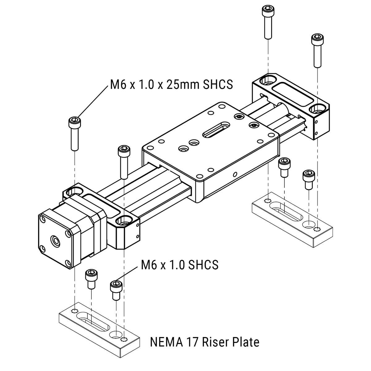
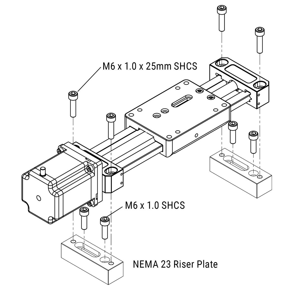
Lead Screw UGA: Mounting with Riser Plates
PBC Linear recommends using low strength threadlocker on mounting screws.
Be sure power is OFF before performing actuator maintenance
- Establish the location where the two riser plates will be installed.
- Drill and tap two M6 x 1.0 threaded holes in the mounting surface for each riser plate (see illustrations below). Drill to a depth appropriate for the application.
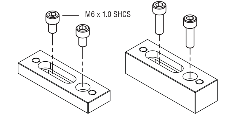
- Attach each riser plate to the mounting surface with two M6 x 1.0 SHCS and torque to 6.5-8.0 N-m/57-70 in-lb. Fastener length to be determined by installer, as appropriate for the application.
- Attach the actuator to each riser plate with two M6 x 1.0 x 25mm SHCS and torque to 6.5-8.0 N-m/57-70 in-lb.
Tools Required
5 mm hex wrench
Parts List
Riser Plates
M6 x 1.0 x 25 mm SHCS
M6 x 1.0 SHCS
42 mm (NEMA 17) Riser Plate Installation
56 mm (NEMA 23) Riser Plate Installation
10 mm Height Riser Block Dimensions
Typically used with 40-42 mm (NEMA 17) motors

20 mm Height Riser Block Dimensions
Typically used with 56-60 mm (NEMA 23) motors

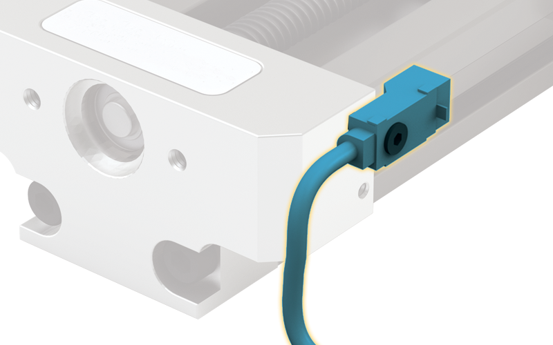
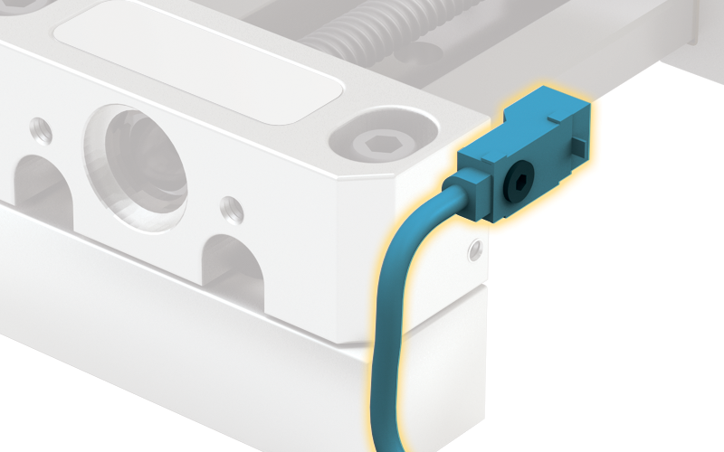
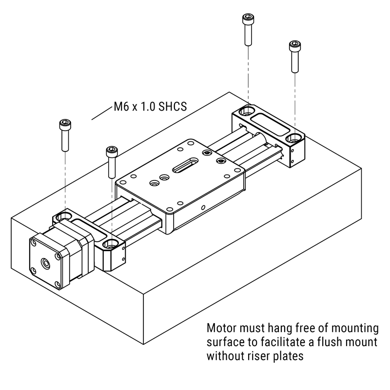
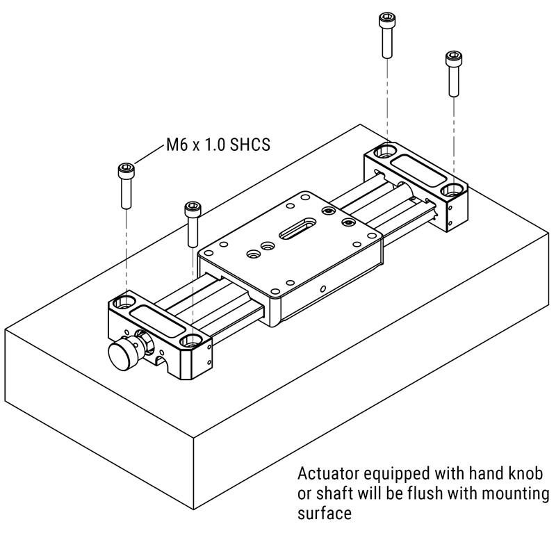
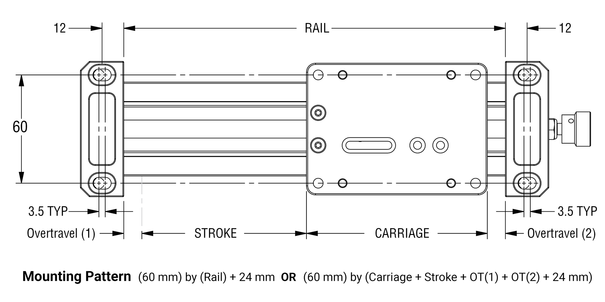
Lead Screw UGA: Mounting with End Blocks
PBC Linear recommends using low strength threadlocker on mounting screws.
Be sure power is OFF before performing actuator maintenance
- Establish the location where the actuator will be installed.
- Drill and tap two M6 x 1.0 threaded holes in the mounting surface for each end block (see illustrations below). Drill to a depth appropriate for the application.
- Attach each end block to the mounting surface with two M6 x 1.0 SHCS and torque to 6.5-8.0 N-m/57-70 in-lb. Fastener length to be determined by installer, as appropriate for the application.
Tools Required
5 mm hex wrench
Parts List
M6 x 1.0 SHCS
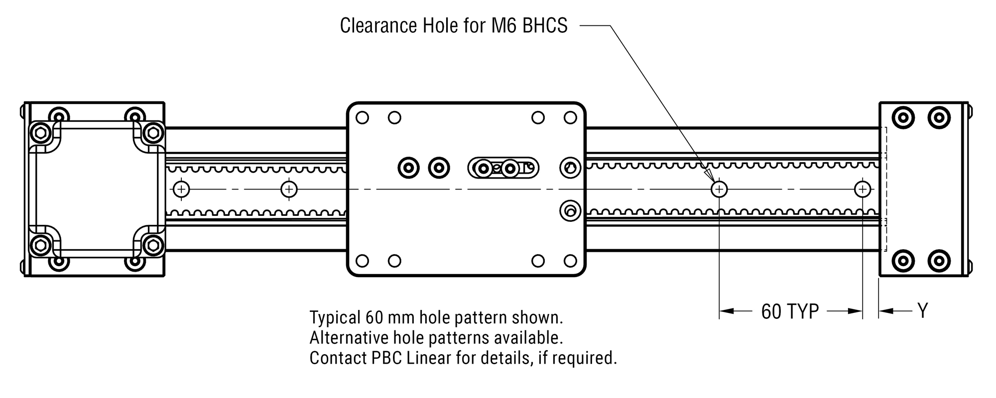
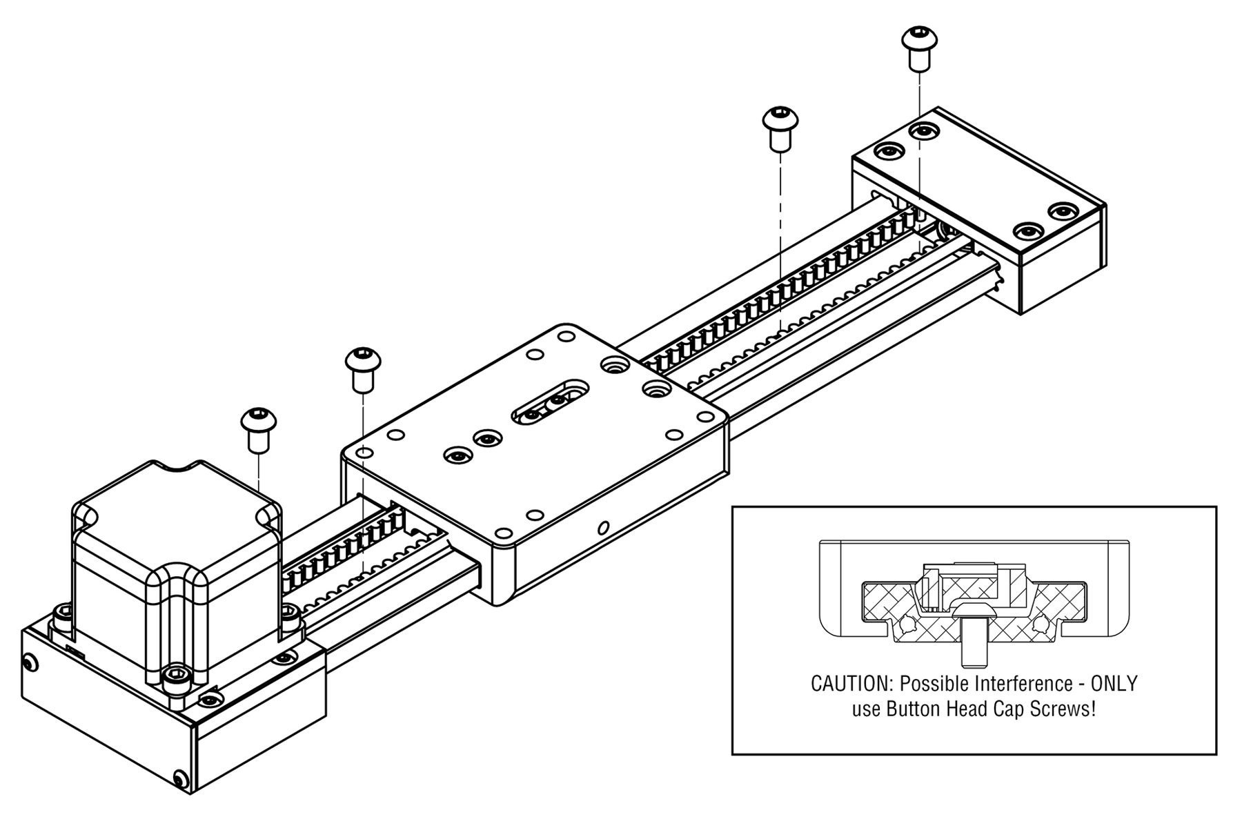
Vertical Belt UGA: Extrusion Mount
PBC Linear recommends using low strength threadlocker on mounting screws.
Be sure power is OFF before performing actuator maintenance
- Establish the location where the actuator will be installed.
- Drill and tap M6 x 1.0 threaded holes in the mounting surface using typical hole pattern shown below or applicable alternative. Drill to a depth appropriate for the application.
- Attach the actuator to the mounting surface with M6 x 1.0 BHCS and torque to 10 N-m/88.5 in-lb. Fastener length to be determined by installer, as appropriate for the application.
Tools Required
4 mm hex wrench
Parts List
M6 x 1.0 SHCS
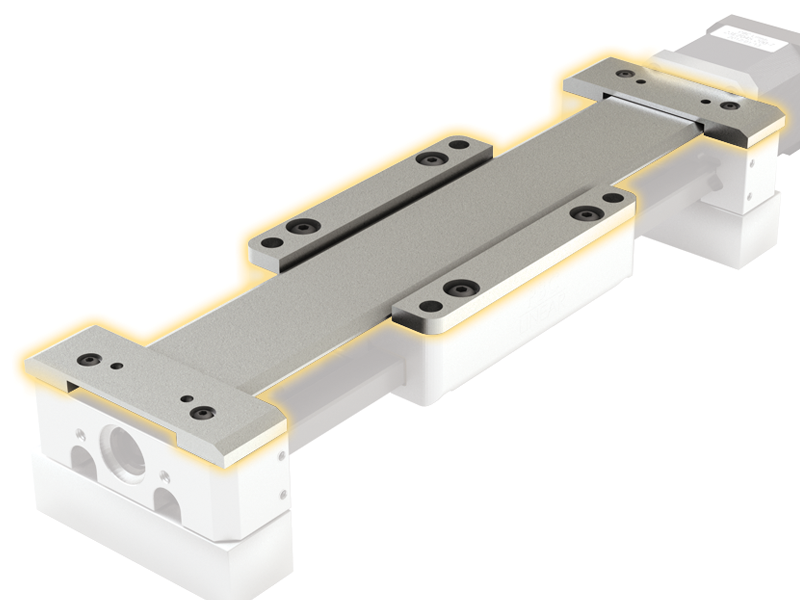
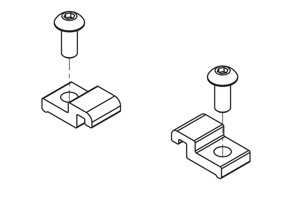
UGT: Mounting with Toe Clamps
Toe Clamp Installation
PBC Linear recommends using low strength threadlocker on mounting screws.
Be sure power is OFF before performing actuator maintenance
- Establish the location where the actuator and toe clamps will be installed.
- Drill and tap an M5 x 0.8 threaded hole in the mounting surface for each single toe clamp, or two M5 x 0.8 threaded holes for each double. See illustrations below.
- Position toe clamps on the actuator as shown in the illustrations below, then install with M5 x 0.8 BHCS fasteners.
Tools Required
3 mm hex wrench
Parts List
M5 x 0.8 SHCS
Standard Double Toe Clamp
Optional Single Toe Clamp
Use when space is limited. Also used to clamp the rail onto a standard carriage for XY systems
Initial Lubrication During Installation (CRT)
Some PBC Linear systems are shipped with a preservative lubrication applied to the raceways. If so, additional lubrication should be applied during installation. Proper lubrication dissipates heat, increases service life, and reduces friction, wear, and corrosion. Recommended lubricants are listed where applicable, but there are some lubricants which SHOULD NOT be used on any SIMO configuration.
DO NOT USE: WD40; motor oil; oils with additives; moly or other filled greases; PTFE sprays, oils, or greases; or sprays containing fluorocarbons or silicone.
Plain Bearing Lubrication (GST - Gliding Surface Technology)
The GST plain bearing utilizes bonded FrelonGOLD®, self-lubricating, maintenance-free bearing surfaces. If desired, adding lubrication will increase life, lessen noise, and lower the coefficient of friction. Oil or grease can be brushed on the raceway, or a lubrication storage system can be added via the optional “JKM” lube kit for GST carriages (Part# UGA040A-JKM-KIT).
IMPORTANT: Oil is recommended for saturating the felt strips in the “JKM” lube kit. If grease is used on bearing surfaces, the felt strip MUST be removed or the grease will cause the strip to act as a brake! DO NOT disassemble a driven system. DO contact a PBC Linear application engineer for guidance regarding felt strip removal.
Recommended Lubricants: way lube oils, lightweight oils, 3-IN-ONE® oils, and lightweight petroleum-based greases.
Proceed as follows:
- Wipe or brush a thin layer of lubricant along the entire length of the guide rail raceways.
- Move the carriage back and forth at least four times to thoroughly distribute lubricant.
V-Guide Bearing Lubrication (CRT - Cam Roller Technology)
The inside of the V-Wheels are sealed for life and require no lubrication during normal operation. The outer race should be routinely inspected for damage and wear. Note: Do not attempt to disassemble V-Wheels.
The V-Guide stainless steel raceways are lubricated by oil-filled, porous polymer lubricators mounted in the carriage. This advanced polymer provides better performance and longer life than similar wiper/lubricators equipped with oil-saturated felt. Note: These lubricators may emit a squealing or chirping sound when replacement is necessary.
Additional lubrication will increase life, lessen noise, and lower the coefficient of friction.
Recommended Grease: Synthetic oil based lithium-soap grease with an ISO VG32-100 viscosity.
Recommended Oil: Synthetic oil CLP or CGLP based on DIN 51517, or HLP based on DIN51524.
Viscosity range should be ISO VG32-100.
Proceed as follows:
- Wipe or brush a thin layer of lubricant along the entire length of the V-Guide raceways.
- Move the carriage back and forth at least four times to thoroughly distribute lubricant.
Relubrication
Linear guide raceways should be relubricated periodically with oil or grease. Recommended lubricants are listed where applicable, but there are some lubricants which SHOULD NOT be used on any SIMO configuration.
DO NOT USE: WD40; motor oil; oils with additives; moly or other filled greases; PTFE sprays, oils, or greases; or sprays containing fluorocarbons or silicone.
The relubrication interval is dependent on many operating and environmental conditions, such as load, stroke, velocity, acceleration, lubrication type, mounting position/orientation, UV exposure, temperature, and humidity. The actual lubrication interval should be determined by tests conducted under actual application conditions.
While the actual relubrication intervals are application specific and determined only through testing, the following “first check” guidelines can typically be used as a starting reference point under “normal” conditions:
Relubrication every 1000 km; 50000 cycles; or six months (whichever occurs first)
Extended Lubrication Interval
If your actuator is equipped with the optional “JKM” lube kit (GST), oil-filled wipers (CRT), or “EZ” lube system (PRT), you can extend the first check to:
Relubrication every 2500 km; 100000 cycles; or one year (whichever comes first)
Extreme Applications
Unusually demanding circumstances (high speeds, extreme temperatures, shock, vibration, contamination, submersion) will require more frequent relubrication intervals
Recommended Lubricants
Plain Bearing (GST - Gliding Surface Technology)
Recommended Lubricants: way lube oils, lightweight oils, 3-IN-ONE® oils, and lightweight petroleum-based greases.
V-Guide Bearing (CRT - Cam Roller Technology)
Recommended Grease: Synthetic oil based lithium-soap grease with an ISO VG32-100 viscosity.
Recommended Oil: Synthetic oil CLP or CGLP based on DIN 51517, or HLP based on DIN51524.
Viscosity range should be ISO VG32-100.
Lead Screw
The PTFE coated lead screw and polymer nut require no lubrication during normal operation, but should be routinely inspected for damage and wear. In certain applications, however, an external lubricant may be desirable. Contact a PBC Linear applications engineer for guidance regarding additional lubrication.
Horizontal and Vertical Belt Tension Adjustment
PBC Linear recommends using low strength threadlocker on mounting screws.
Be sure power is OFF before performing maintenance.
- Push the carriage to the idle end of the assembly (see Figure 1).
- Using a 2.5 mm hex wrench, loosen both belt adjustment screws slightly (see Figure 1). There should be some tension to prevent the belt from detaching.
- Place a half inch diameter dowel pin, two to three inches long, between the carriage and the idle end block (see Figure 2).
- While pushing the carriage against the dowel pin to keep the belt taut, tighten both belt adjustment screws.
- Back the carriage up 300 mm from the idle end block (see Figure 3).
- Depress the belt with a tension gage positioned centrally between the carriage and the idle end block (see Figure 3).
- Pushing the belt halfway down should indicate 3 lbf (13.3 N), plus or minus .5 lbf (2.22 N).
- If the tension is incorrect, repeat the above procedure, either increasing or decreasing the tension as required to reach 3 lbf (13.3 N), plus or minus .5 lbf (2.22 N).
Tools Required
2.5 mm hex wrench
Tension Gage
Parts List
1/2 inch Dowel Pin
(two to three inches long)


Horizontal Belt Replacement
PBC Linear recommends using low strength threadlocker on mounting screws.
Be sure power is OFF before performing maintenance.
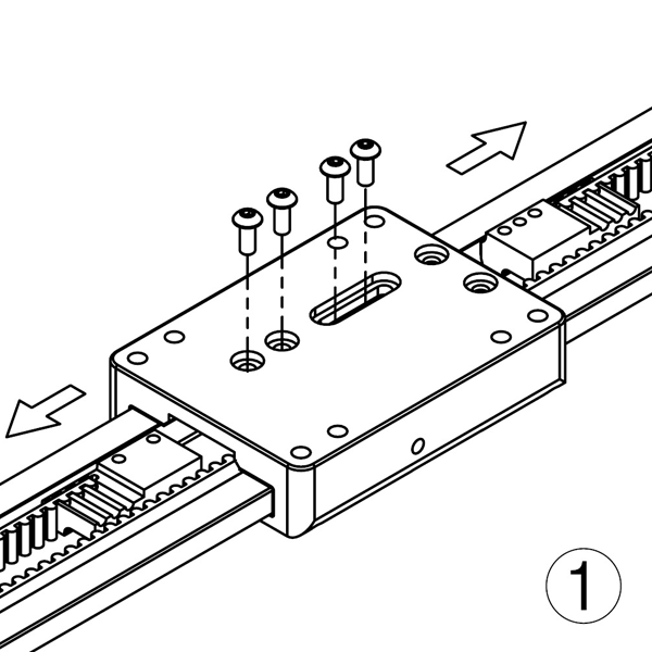
- Remove four M4 button head cap screws securing the pulley clamps, then pull both clamps from beneath the carriage.
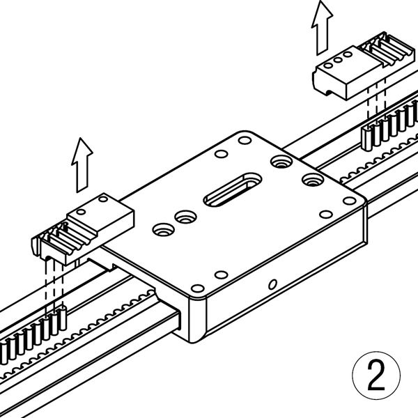
- Remove both pulley clamps from the belt.
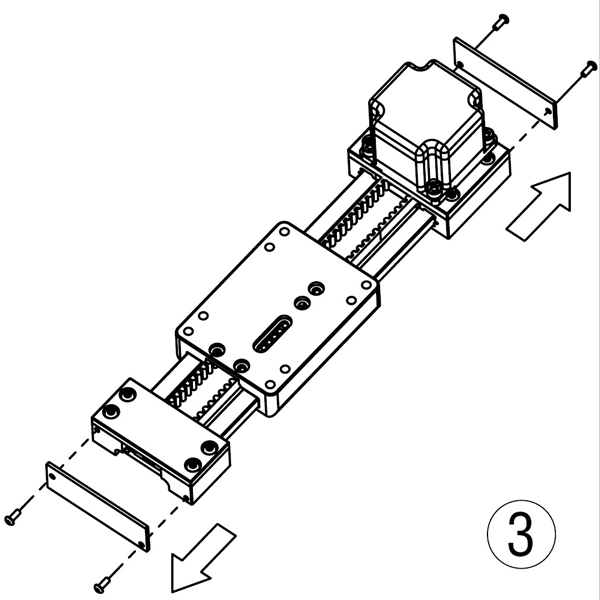
- Remove the actuator end plates, if applicable.
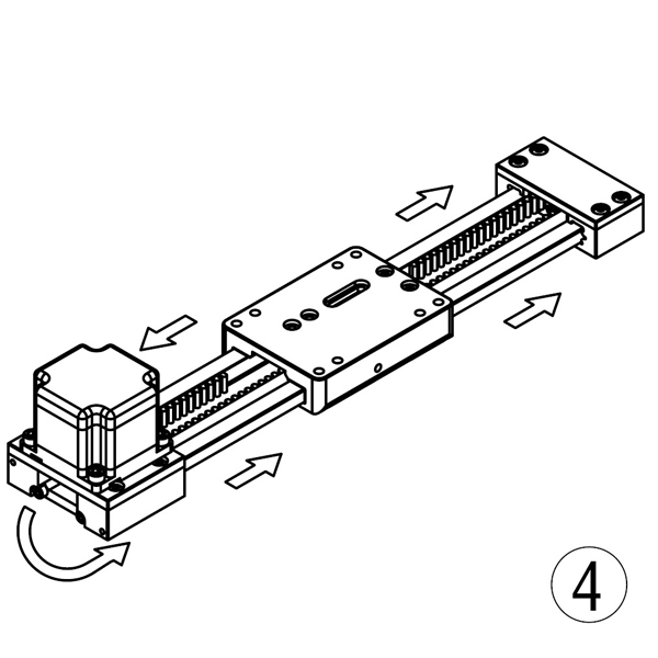
- Pull the belt around the pulley through the drive end block, then around the pulley through the idle end block, then pull it free of the actuator.
- Feed the new belt through the actuator as shown in the illustration. Be sure not to miss a tooth when wrapping the belt around the pulleys!
- Insert the new belt end into the fixed pulley clamp. Be sure that all belt teeth engage the clamp.
- Slide the fixed pulley clamp under the carriage, then fully tighten the two M4 x 0.7 button head cap screws that secure it in place.
- Insert the other end of the belt into the adjustable pulley clamp. Be sure that all belt teeth engage the clamp.
- Slide the adjustable pulley clamp under the carriage. Insert, but do not fully tighten the two button head cap screws. Follow the “Horizontal Belt Tension Adjustment” procedure on the previous page to set belt tension.
Tools Required
2.5 mm hex wrench
Parts List
Pulley Belt
M4 x 0.7 BHCS


Vertical Belt Replacement
PBC Linear recommends using low strength threadlocker on mounting screws.
Be sure power is OFF before performing maintenance.
- Remove four M4 button head cap screws securing the pulley clamps, then pull both clamps from beneath the carriage.
- Remove both pulley clamps from the belt.
- Remove the actuator end plates, if applicable.
- Pull the belt around the pulley through the drive end block, then around the pulley through the idle end block, then pull it free of the actuator.
- Feed the new belt through the actuator as shown in the illustration. Be sure not to miss a tooth when wrapping the belt around the pulleys!
- Insert the new belt end into the fixed pulley clamp. Be sure that all belt teeth engage the clamp.
- Slide the fixed pulley clamp under the carriage, then fully tighten the two M4 x 0.7 button head cap screws that secure it in place.
- Insert the other end of the belt into the adjustable pulley clamp. Be sure that all belt teeth engage the clamp.
- Slide the adjustable pulley clamp under the carriage. Insert, but do not fully tighten the two button head cap screws. Follow the “Vertical Belt Tension Adjustment” procedure on the previous page to set belt tension.
Tools Required
2.5 mm hex wrench
Parts List
Pulley Belt
M4 x 0.7 BHCS