Round Shaft Technology
INCH SERIES
Simplicity® Linear Plain Bearings
Linear Precision Ball Bearings
Linear Ball Bearings – Precision Plus Self-Aligning
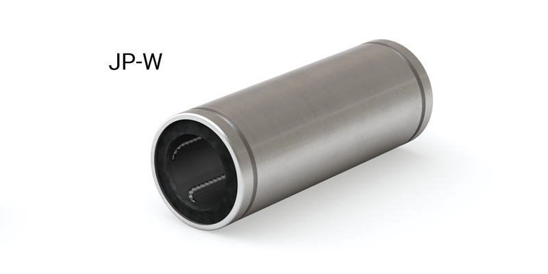
Linear Ball Bearings – Double Wide
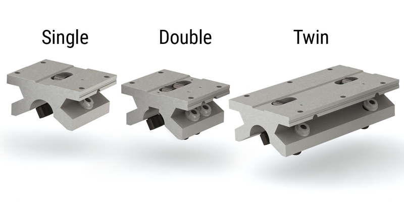
Simplicity Pillow Blocks
Simplicity Pillow Blocks – Twin
Linear Ball Bearing Pillow Blocks
Linear Ball Bearing Pillow Blocks – Twin
Simplicity Flange Mounts
Die Set Flange Mounts
Die Set Bushings
Simplicity Sleeve Bearings
Roller Pillow Block Bearings
Shaft & Rail Systems

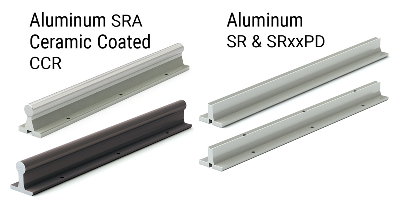
Support Rail Systems
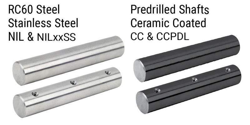
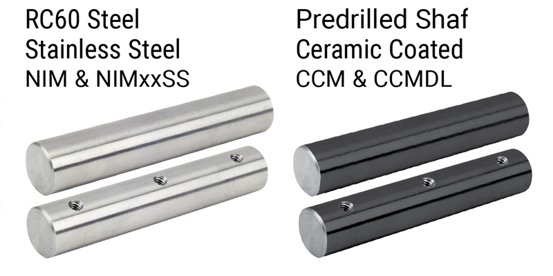
Simplicity® 60 Plus® Shafting
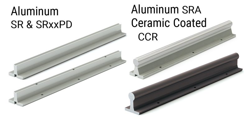
Support Rails & Assemblies
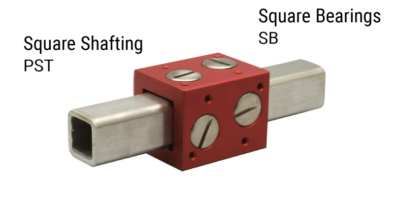
Square Shafting, Bearings & Plugs
ISO METRIC SERIES
Simplicity Linear Plain Bearings
Linear Ball Bearings – Precision Plus Self-Aligning
Linear Precision Ball Bearings
Linear Ball Bearings – Double Wide
Simplicity Pillow Blocks
Linear Ball Bearing Pillow Blocks
Thin Wall Ball & Plain Bearings
Simplicity Flange Bearings – Single
Simplicity Flange Bearings – Double
Simplicity Flange Bearings – Center Flange
Linear Ball Bearings – Single
Linear Ball Bearings – Double
Linear Ball Bearings – Center Flange
Die Set Bushings
Simplicity Sleeve Bearings
Roller Pillow Block Bearings

Simplicity® 60 Plus® Shafting
Support Rails & Assemblies
JIS METRIC SERIES
Simplicity Linear Plain Bearings
Linear Precision Ball Bearings
Linear Ball Bearings – Double Wide
Simplicity Flange Bearings – Single
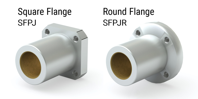
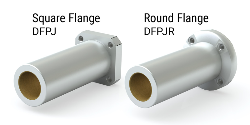
Simplicity Flange Bearings – Double
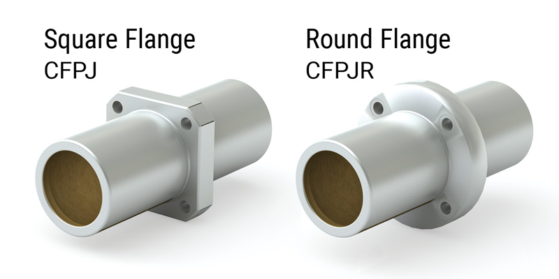
Simplicity Flange Bearings – Center Flange
Linear Ball Bearings – Single
Linear Ball Bearings – Double
Linear Ball Bearings – Center Flange

INCH SERIES PLAIN & BALL BEARING LINEAR SLIDES
Simplicity Linear Slides
Simplicity Linear Slides
Simplicity Linear Slides
Simplicity Linear Slides
Simplicity Linear Slides
Check Out PBC Linear Configurators
Shafting • Roller Pillow Block • Support Rail Assembly
The PBC Linear configuration tools allow you to customize and configure linear components to exact specifications.
- Simple steps to configure and select product offerings
- Custom CAD file delivered in minutes
- Custom quote generated quickly and easily
- Visit pbclinear.com/tools/configure-quote and start designing!
Linear Shafting Engineered for Maximum Linear Bearing Performance
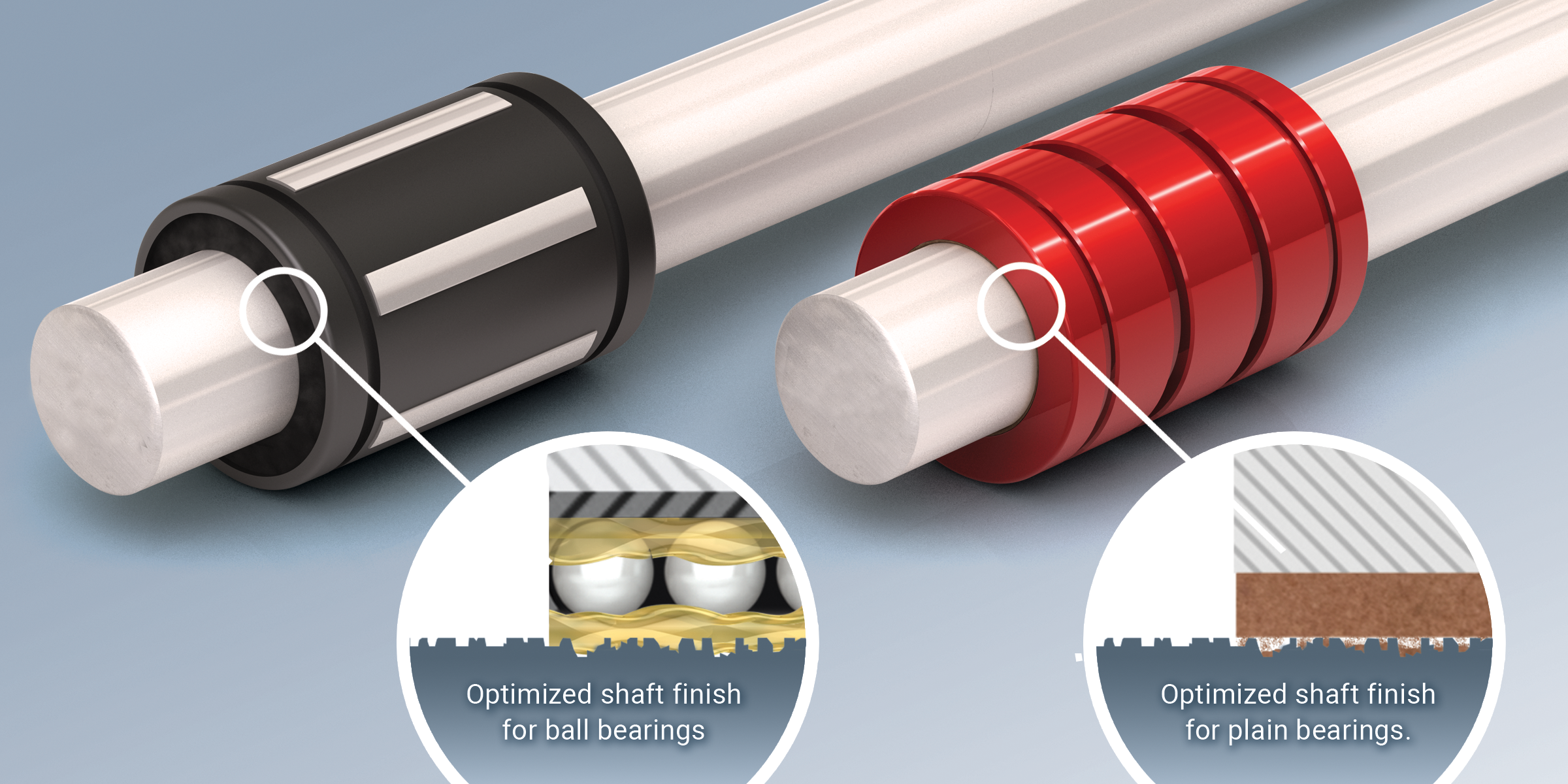
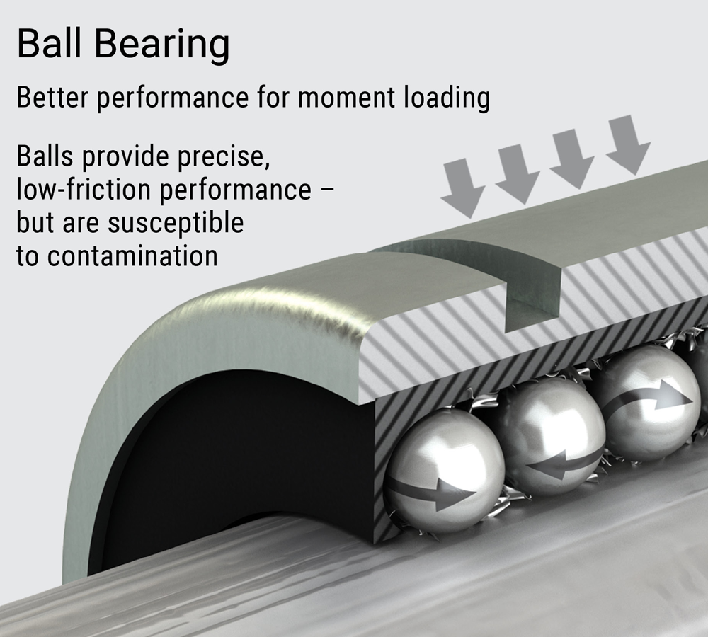
Linear Ball Bearings
The right amount of microscopic surface texture holds lubrication for consistent smooth ball rotation minimizing the effects of metal-to-metal contact.
- Excellent Rigidity: providing smooth, quiet operation
- Extremely Low Friction: rolling elements provide consistent anti-friction movement
- Outer Shell: Available with steel jacket or self-aligning super bearing shell
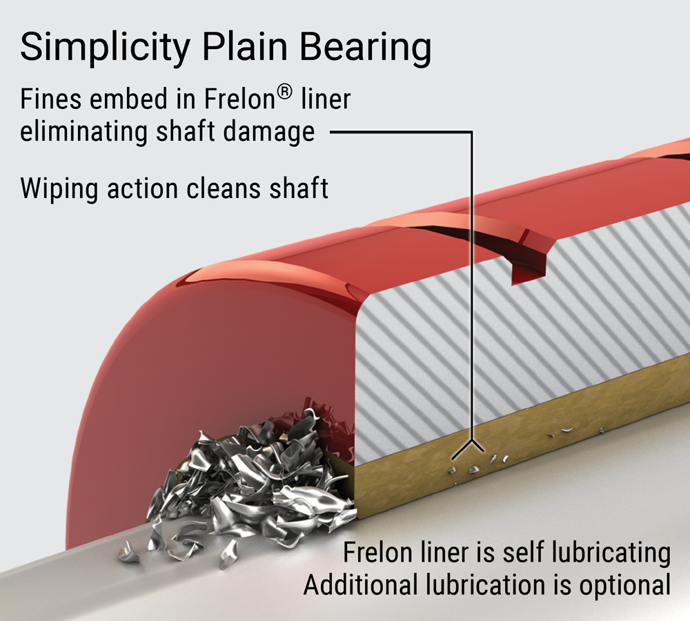
Simplicity Plain Bearings
The Frelon® break-in and transfer process operates at maximum efficiency with Simplicity 60 Plus Shafting resulting in true self-lubrication and the longest life possible.
- Self-Lubricating: maintenance-free, additional lubrication optional
- Wide Temperature Ranges: (-400°F/+400°F), (-240°C/+204°C)
- Vibration Damping: eliminates fretting corrosion
⚠ Only certified Simplicity 60 Plus Shafting provides maximum bearing performance.
Simplicity Plain Bearings
Simplicity Plain Bearing Product Overview
Linear Plain and Ball Bearings
Good engineering principles dictate that the best bearing design be utilized for any given bearing application. Each type of bearing has advantages and disadvantages. Strengths or limitations can make it a clear choice depending on the application environment. At other times, an engineer will have a choice because multiple types of bearings can meet the need.
In 1983, PBC Linear® created the self-lubricating Simplicity linear bearing – a technology that solves problems in dirt, vibration, shock loading, cleanrooms, welding, foundry, and washdown situations where linear ball bearings regularly fail.
Today, PBC Linear provides a full range of linear motion solutions for both plain bearing and ball bearing applications – giving engineers the versatility to choose the right bearing for the application. Chart to the right here is intended to help guide in that decision making process.
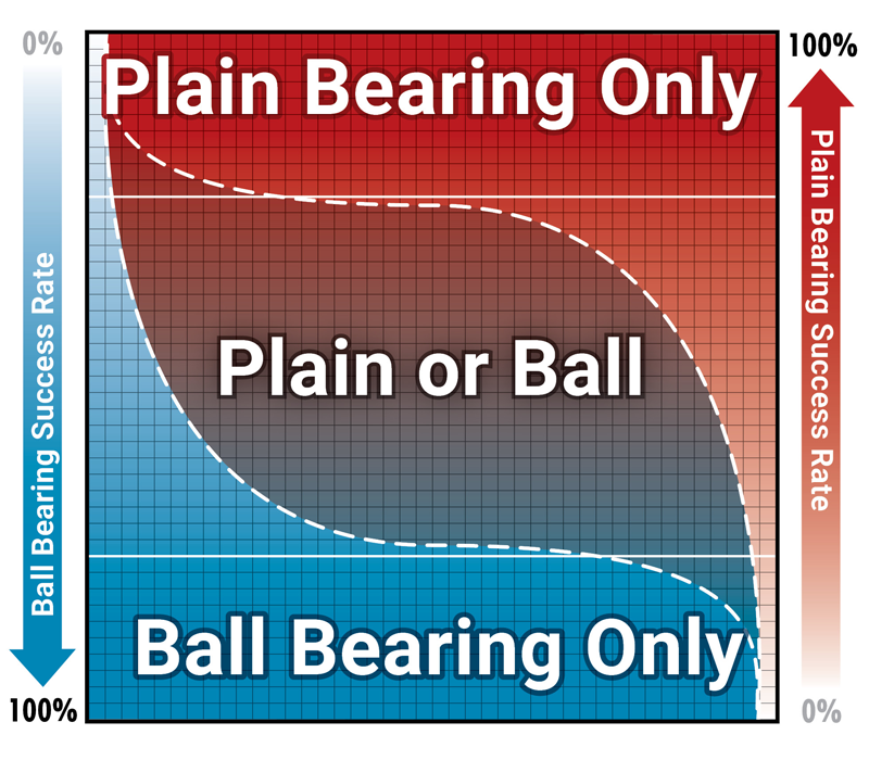
| Bearing Type | Load | Moment Loads | Linear Speed | Coefficient Of Friction | Precision | Environment |
|---|---|---|---|---|---|---|
Plain
|
Up to 20x ball bearings |
Limited due to 2:1 ratio |
Up to 300 sfm (1.524 m/sec) dry running Up to 825 sfm (4.19 m/sec) with lubrication |
FrelonGOLD® = 0.125 Consistent over life and in a variety of environments |
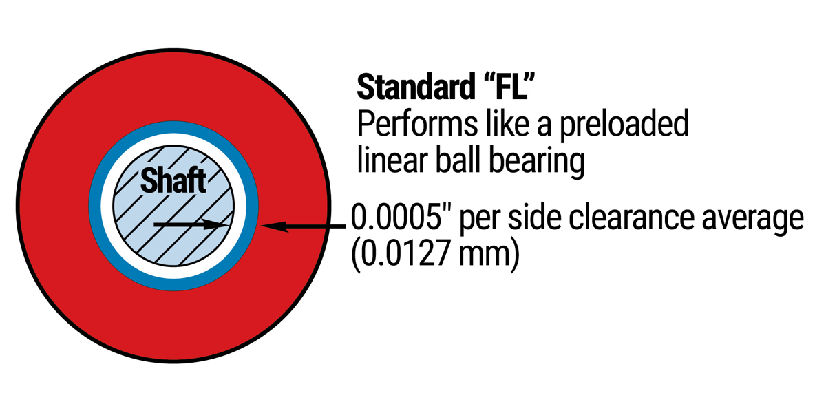
Precision running clearance = 0.0005" (0.0127 mm) per side |
Excels in contaminated, wet, dry, and clean room applications |
Ball
|
Limited due to point-to-point contact of balls to shaft |
Moderate to good High moment loads can cause increased wear and shorten bearing life |
Up to 3 m/sec (590 sfm) Always requires lubrication |
Average = 0.002 Can change dramatically dependent on environmental conditions |
Can be preloaded, virtually eliminating play This can shorten life |
Will corrode and fail in contamination |
Simplicity Plain Bearing Performance Benefits
Frelon® + Precision Bearing Technology = Simplicity
- The Frelon liner is bonded to the bearing shell at the molecular level, which transfers the load and dissipates heat buildup throughout the bearing
- Will not rust or corrode due to anodized aluminum or 316 stainless steel shell
- Patented self-aligning capabilities are standard
- Provides both linear, oscillating, rotary, or any combination of motions
- Maintenance free operation
- Smooth and quiet operation – plus long life
- Highly accurate – all critical surfaces are ground on precision bearing grinders
- Will not catastrophically fail or damage shaft
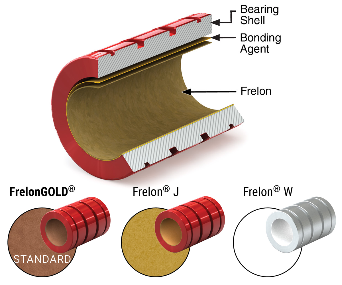
- FrelonGOLD® – dark gold high performance material compatible with RC60 hardened steel shafting, RC70 ceramic coated, and 400 series stainless steel shafting.
- Frelon J – yellow material formulated to provide the optimum performance with 300 series stainless steel and softer shafting such as bare aluminum.
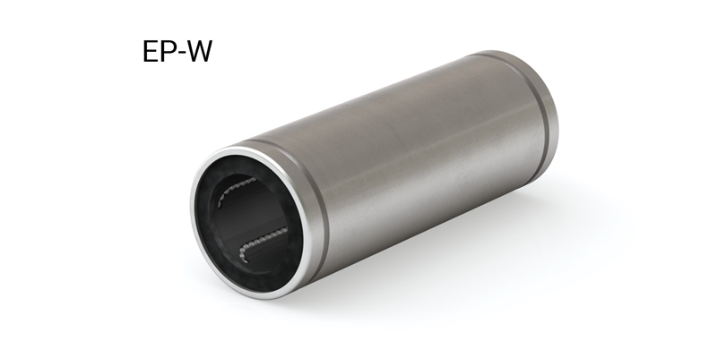
- Frelon W – white color, food-grade liner, FDA compliant, compatible with stainless steel and softer metal shafting.
- PBC Linear's unique bonding process facilitates the ability to provide solutions for applications with a range of additional bearing liner materials. Contact PBC Linear to discuss your specific application.
Frelon Bearing Liner Materials
The Frelon liners are compounds of PTFE and fillers developed for improved performance over other bearings. They provide low wear, low friction, self-lubrication, and high strength.
Filler Benefits:
- High load capacity
- High strength
- Low wear rate vs. other materials

PTFE Features:
- Self-lubricating
(runs without added lubricant) - Embeddability of hard particulate
- Wide temperature range
(-400°F to +400°F)
(-240°C to +204°C) - Chemically inert
- Vibration damping
(no metal-to-metal contact)
Simplicity 60 Plus® Shafting
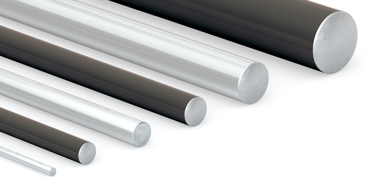
The PBC Linear development team, working in close conjunction with engineers from Lee Linear®, have together formulated a linear shaft designed specifically for optimal bearing performance – Simplicity 60 Plus Shafting. Advanced process capabilities maintain the ideal surface finish resulting in the longest life and highest performing shaft-to-bearing combination.
Don’t be misled–all shafting is not alike! Don’t settle for below average performance. The smoothest shafting is NOT always the best for all situations. In most applications, smoother does not equal better; in fact, it means decreased performance and shortened life. A shaft surface finish of 8-12 Ra is the optimal smoothness for linear plain and ball bearings.
Simplicity 60 Plus Shafting provides maximum linear bearing performance and the following features:
- Optimized shaft surface finish for plain bearings
- Customizable length and machined features via the configurator with no minimum quantities
- Faster Made in the USA
⚠ Only certified Simplicity 60 Plus Shafting provides maximum linear bearing performance.
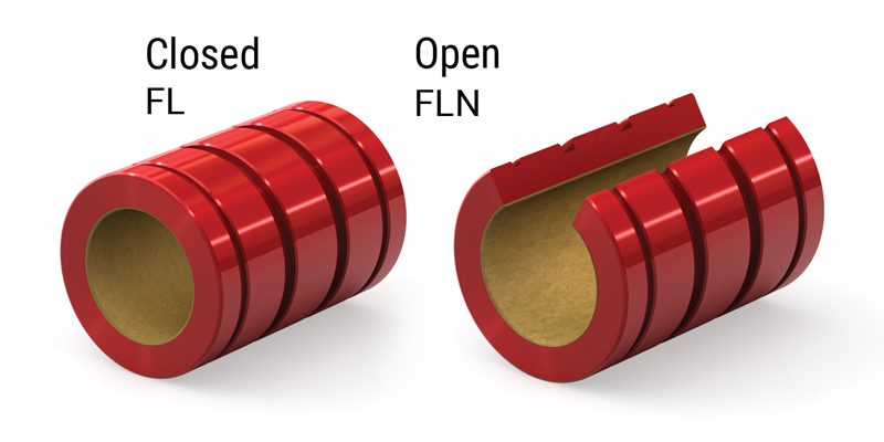
Running Clearance
Simplicity bearings are available with two classes of running clearance:
PRECISION–“FL”:
- Performs like a preloaded ball bearing
- Tightest running clearance approximately 0.001" (0.025 mm)
- Used in applications that require high precision
⚠ CAUTION
Not recommended for all parallel shaft applications. Any misalignment can cause binding on the shaft. Recommend: Compensated–“FLC” (see below).
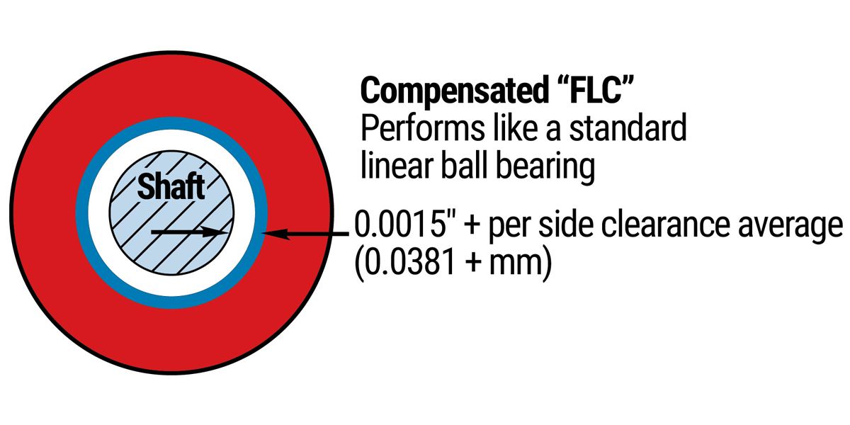
COMPENSATED–“FLC”:
- Performs like a standard ball bearing
- Additional clearance built into the I.D.–all other dimensions are the same as the precision bearings
- Ideally suited for parallel shaft applications
Note: Many parallel shaft applications will run “FL” precision on one rail and “FLC” compensation on the opposite rail to accommodate slight misalignments.
Bearing Shell
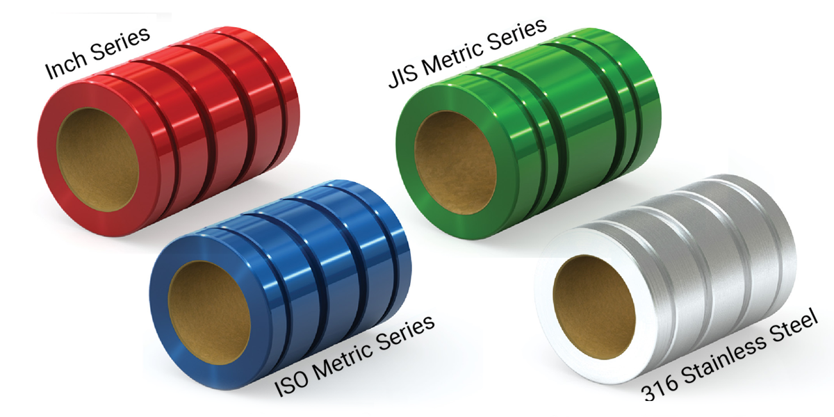
Simplicity bearings are available in a variety of configurations to help meet specific application needs:
- Standard is aluminum alloy with anodized finish
- 316 stainless steel (no plating)
MATERIALS:
- Aluminum Alloy – Is a heat treated and artificially aged aluminum with good strength and corrosion resistance.
- 316 Stainless Steel – Has an excellent corrosion resistance and is widely used by the paper, food, and other industries.
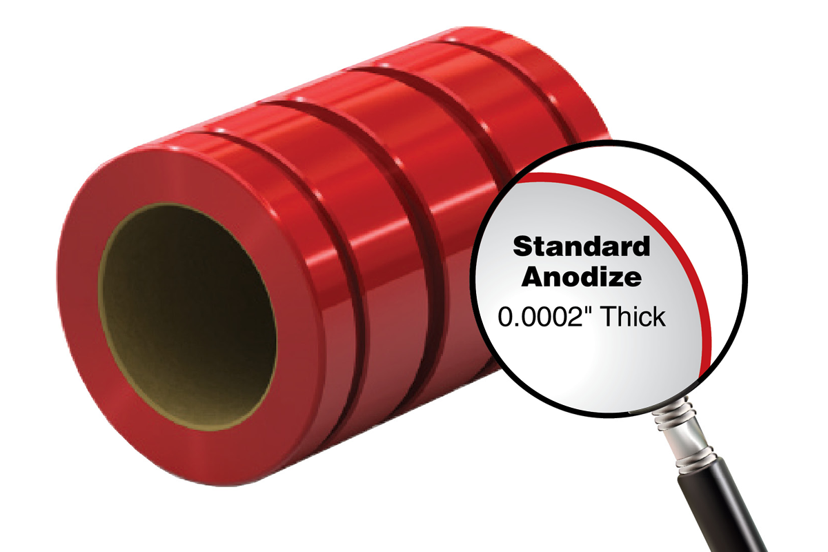
FINISHES:
- Aluminum Alloy – Is a heat treated and artificially aged aluminum with good strength and corrosion resistance.
- Standard Anodized – A sulfuric bath anodizing with a nickel acetate seal that will stand up to 14 days exposure in a 5% salt spray solution at 96°F. It is applied at a 0.0002” thickness.
⚠ Only certified Simplicity 60 Plus Shafting provides maximum linear bearing performance.
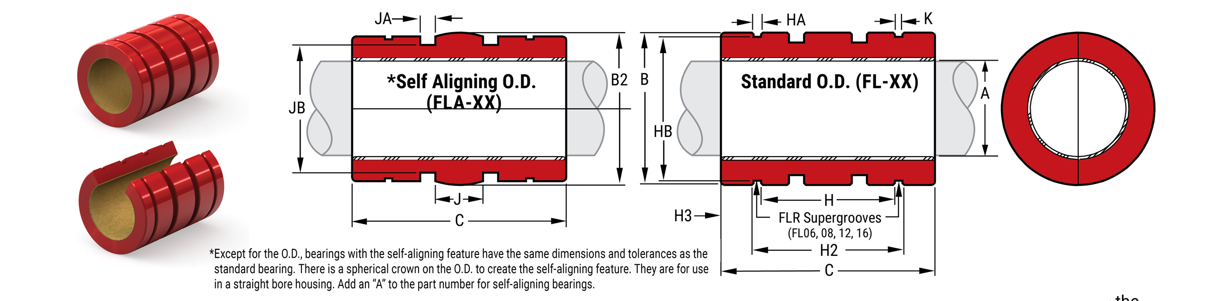
Self-Alignment Feature
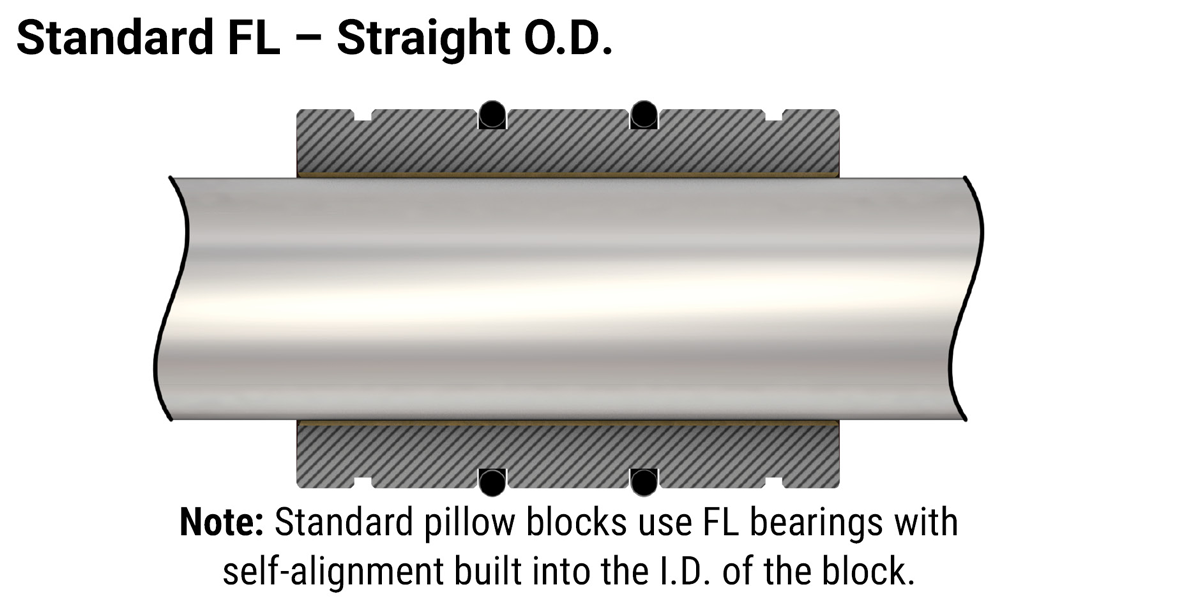
Simplicity bearings are available with a standard straight O.D. or a crowned self-aligning O.D.
FL – (Standard):
- Straight O.D.
- Standard pillow blocks have the self-aligning capability designed into the block using standard “FL” bearings for the final assembly
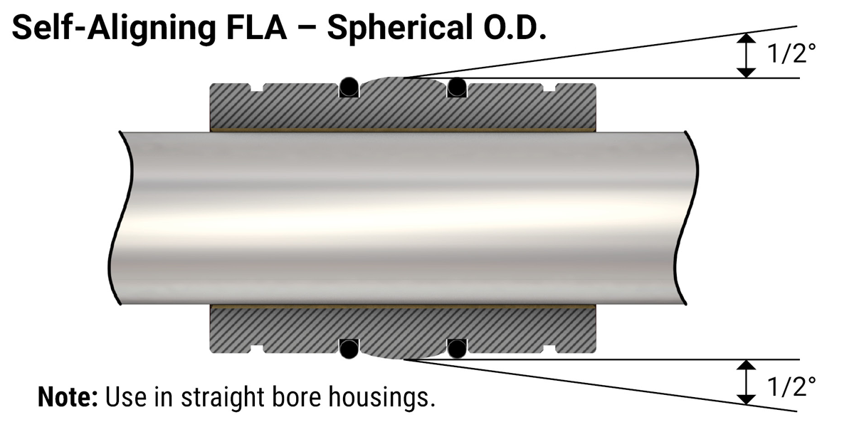
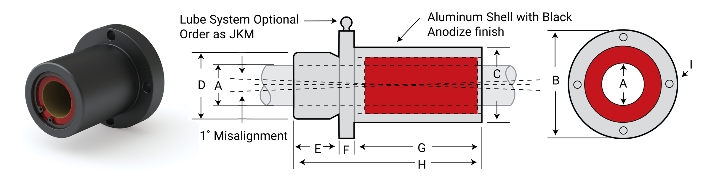
FLA – (Self-aligning O.D.):
- Has a crown on the O.D. allowing the bearing to re-align itself in binding situations
- Specifically designed to easily retrofit straight bore housings
- The bearing will allow 1/2° of misalignment capability from centerline (1° overall)
- O-rings can be used on either side of the crown to cushion and eliminate clatter in operation (sold separately)
Pillow Blocks
- Made of aluminum alloy
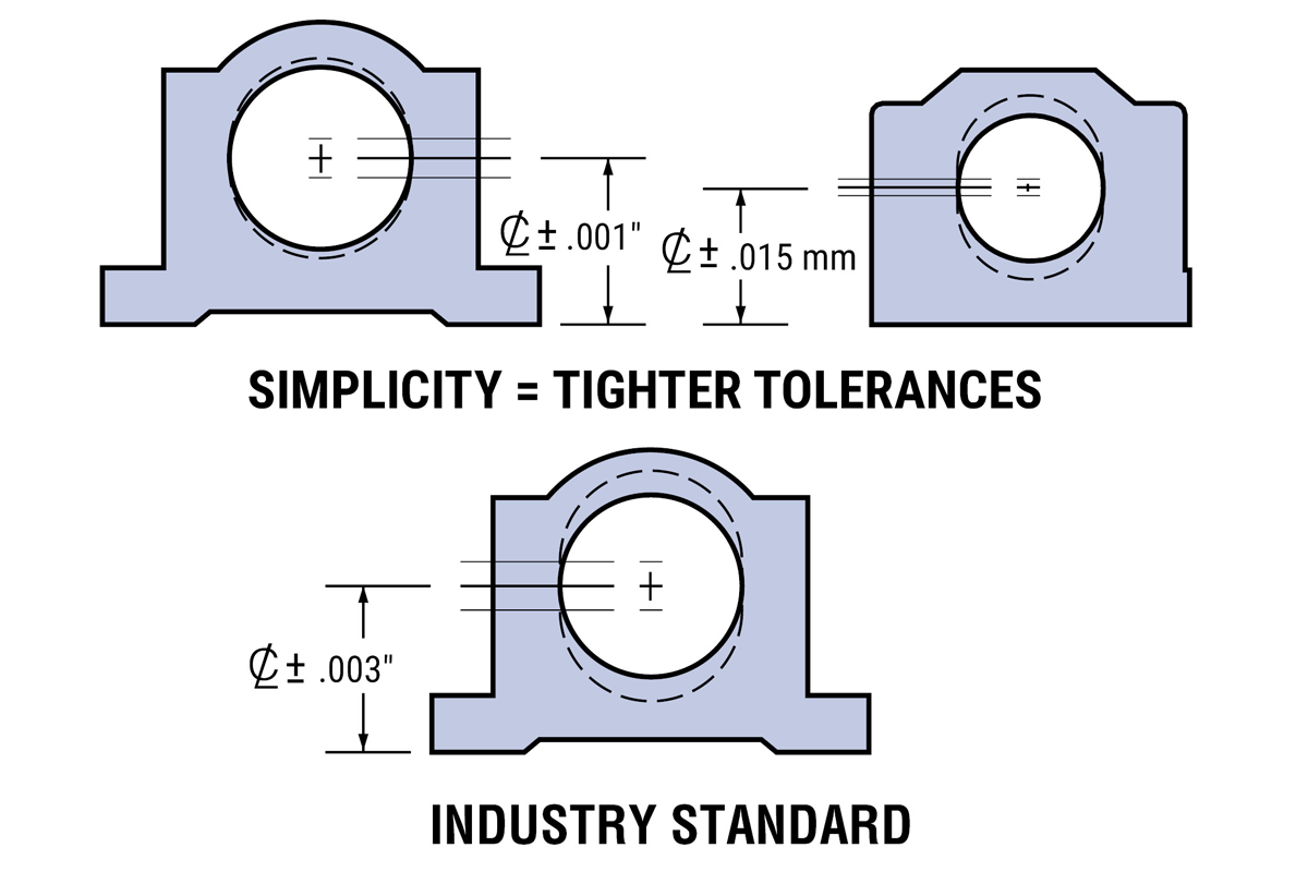
- Pillow blocks are interchangeable with industry standard ball bearing pillow blocks
- Critical centerline dimensions hold accuracy within ±0.001" on inch sizes and ±0.015 mm on metric sizes
FINISHES:
- Clear anodized finish (Standard)
Standard pillow blocks have built-in self-alignment in all directions:
- Standard pillow blocks have 1/2° misalignment from centerline
- This feature is built into the housing with a spherical radius at the midpoint of the block
- This self-aligning capability will allow for some shaft deflection and misalignment
Rigid or straight bore housings are available:
- This does not allow for any self-alignment and provides a very rigid assembly
- They are typically used in single shaft applications
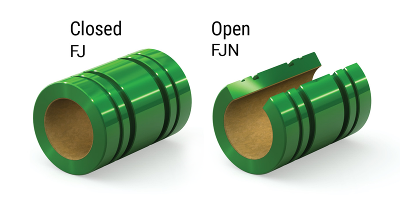
Open Bearings Orientation
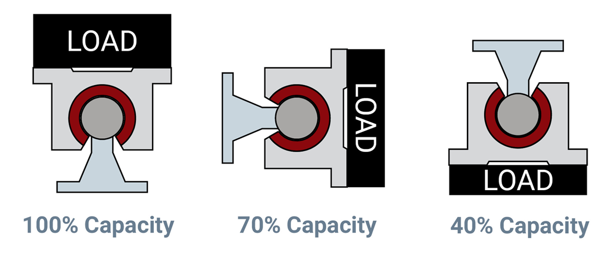
Simplicity bearings can operate in any orientation. Load capacities will vary on open bearings depending on the orientation in which they are being used.
Load Capacity of Liner
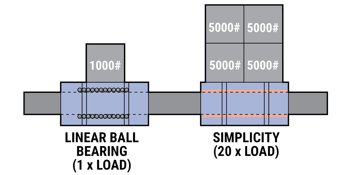
Simplicity bearings can carry from 4 to 20 times the load of a linear ball bearing.
| Bearing Material | Static Load Capacity |
|---|---|
| FrelonGOLD® | 3000 psi or 210.9 kgf/cm2 |
| Frelon® J / Frelon® W | 1500 psi or 105.45 kgf/cm2 |
- Allows the engineer to maintain performance in a smaller designed package.
Example: Simplicity 1/2" I.D. = 1" I.D. linear ball bearing - Shock loads and vibration are absorbed
- Metal–to–metal contact is eliminated providing a smoother, quieter running assembly
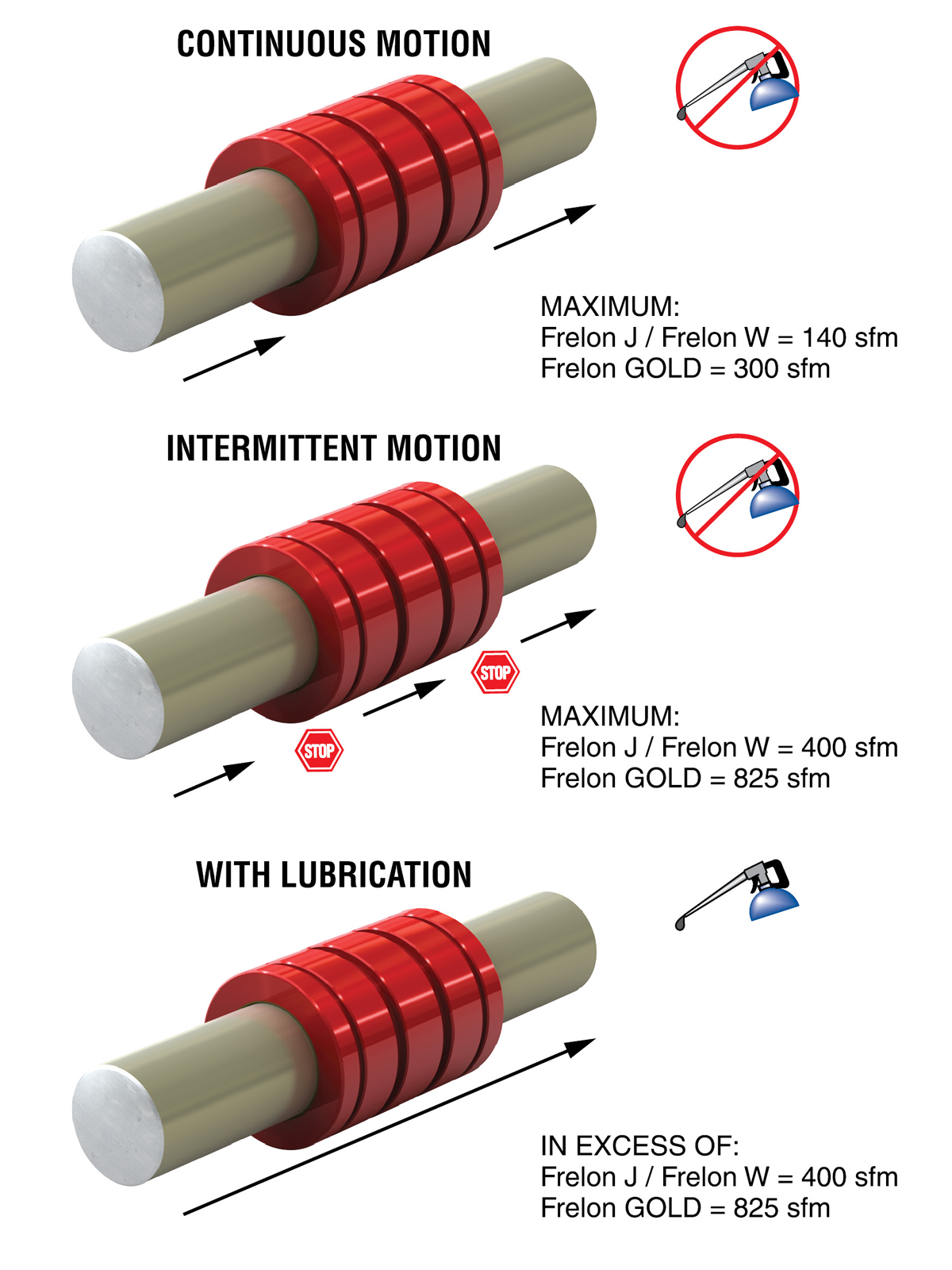
Speed Characteristics
Exceeding these speeds causes frictional heat and accelerates liner wear.
| Bearing Material | No Lube Continuous Motion |
No Lube Intermittent Motion |
With Lubrication* |
|---|---|---|---|
| FrelonGOLD® | 300 sfm 60 in/sec. 1.524 m/sec. |
825 sfm 165 in/sec. 4.19 m/sec. |
825 sfm 165 in/sec. 4.19 m/sec. |
| 140 sfm 28 in/sec. 0.711 m/sec. |
400 sfm 80 in/sec. 2.03 m/sec. |
400 sfm 80 in/sec. 2.03 m/sec. |
|
| Frelon® J / Frelon® W | 140 sfm 28 in/sec. 0.711 m/sec. |
400 sfm 80 in/sec. 2.03 m/sec. |
400 sfm 80 in/sec. 2.03 m/sec. |
*Depending on the lubrication used, loads, and frequency of continuous or intermittent motion, speeds can be in excess of the numbers shown.
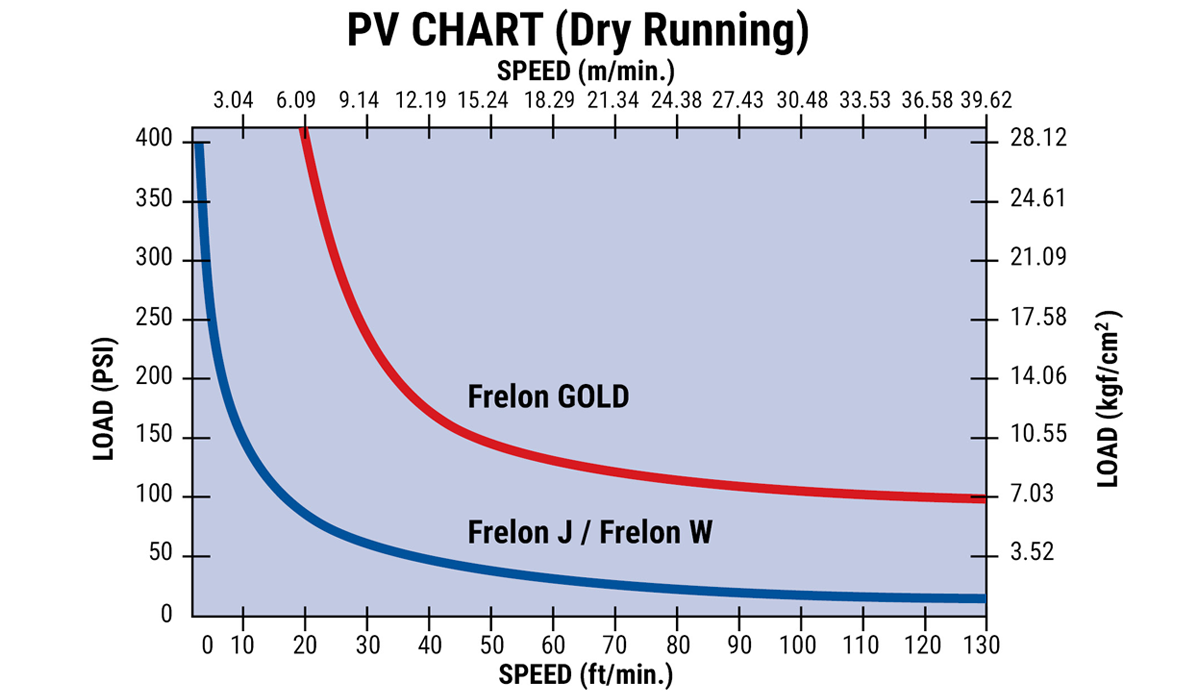
Performance Ratings (for Linear Motion)
Plain bearings are rated by their limiting PV, which is a combination of load over a given surface area and the velocity.
| Bearing Material | MAX. “PV” | MAX. “P” | MAX. “V” (No Lubrication) |
|---|---|---|---|
| FrelonGOLD® | 20000 (psi x ft./min.) or 430 (kgf/cm2 x m/min.) |
3000 psi or 210.9 kgf/cm2 |
300 sfm or 91.44 m/min. |
| Frelon® J / Frelon® W | 10000 (psi x ft./min.) or 215 (kgf/cm2 x m/min.) |
1500 psi or 105.45 kgf/cm2 |
140 sfm or 42.66 m/min. |
PV = The performance measurement of plain bearings
PV = P x V where P = pressure (load) in psi (kgf/cm2)
V = velocity (speed) in sfm (m/min.)
Note: All three parameters must be met by an application for the bearing to perform properly.
Wear Rate/Life Expectancy
The life expectancy of a Simplicity bearing is dependent on application parameters:
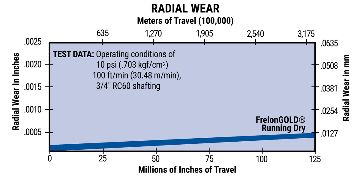
- Shaft hardness, surface finish, and preparation
- Length of travel
- Temperature
- Contamination
- Running clearance
- Lubrication
- Speed
The Radial Wear chart gives a guideline for a typical application at 10 psi (.703 kgf/cm2) traveling at 100 ft./min. (30.48 m/min.).
Factors Affecting Wear Rate/Life
Shafting requirements for Frelon® bearing materials include:
BEST PERFORMANCE:
- Finish of 8–12 Ra
- Hardness of RC 60
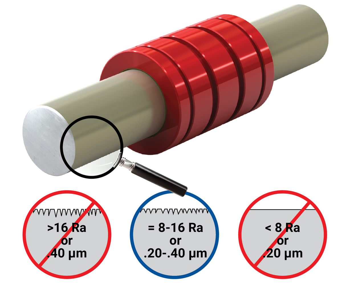
ACCEPTABLE PERFORMANCE:
- Finish of 8–16 Ra
- Hardness of RC 35
- Surface finish requirements apply to all Frelon bearing materials
- Rougher shafting can be used, but both bearing and shafting will wear at accelerated rates and binding may occur
Note: Consult factory if using chrome plated shafting that is polished to < 8 Ra
Cantilevered Loads
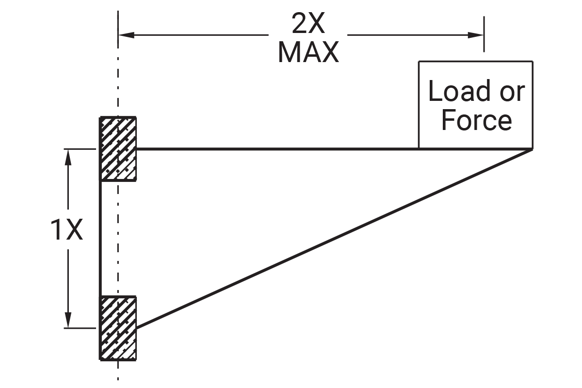
- Maximum 2:1 ratio
- 1x = bearing separation on same shaft
- 2x = distance from shaft to load or force
Example: If 2x equals 10" then 1x must be at least 5"
⚠ CAUTION
Binding will occur if the 2:1 ratio is exceeded.
Transfer Process of Liner to Shaft
The interaction of the Frelon® material and the shafting creates a natural, microscopic transfer of the Frelon to the running surface. A thin film is deposited on the shaft, and the valleys in the surface finish are filled in with Frelon material during the initial break-in period. This transfer creates the self-lubricating condition of Frelon riding on Frelon.
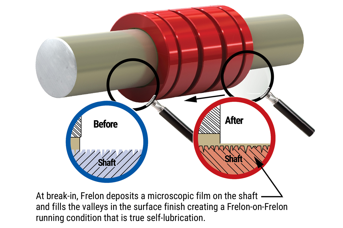
This break-in period varies depending on several criteria:
- Preparation of the shafting prior to installation – it is best to clean the shafting with a 3-in-1 type oil before installing the bearings.
This ensures that the surface will receive a full transfer of material - Speed, load, and length of stroke specific to the application – typically the initial transfer process will take approximately 50-100 strokes of continuous operation. The running clearance on the bearing will increase an average of 0.0002" to 0.0005", depending on the length of the stroke and surface requiring the transfer.
- How often the shafting is cleaned – if the shafting is cleaned regularly, increased wear will be seen in the bearings. This is due to the transfer process being performed over and over again.
⚠ CAUTION
Do not repeatedly clean the shafting with alcohol. This will remove the previously transferred material entirely and increase the wear to the bearing liner.
⚠ CAUTION
Do not use smooth chrome shafting with Frelon bearings. The surface finish is less than 8 Ra and does not maintain proper transfer of Frelon material. This will result in accelerated wear.
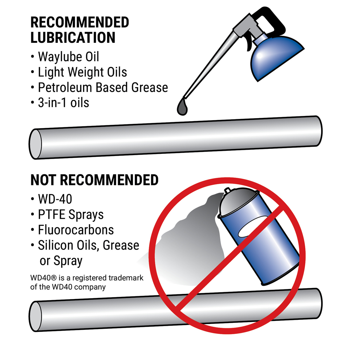
Lubrication
- Reduce friction up to 50%
- Minimize wear of liner
- Reduce heat buildup allowing greater speeds. Actual speeds achieved are dependent on type of lubricant and frequency of application
- Aid in cleaning the shafting for a proper transfer process. A minimum of initial lubrication of Simplicity bearings is strongly recommended

Chemical Resistance
Simplicity bearings stand up to harsh environments and provide excellent performance in a submerged condition.
FrelonGOLD® – the fillers in the material can be attacked by deionized water and other harsh chemicals
Frelon J – almost universal chemical inertness: Only molten sodium and flourine at elevated temperatures and pressures show any signs of attack
Frelon W – A white colored food-grade liner that is FDA compliant
Anodized Aluminum Shell (Standard) – good chemical resistance in most industrial applications
316 Stainless Steel Shell (Optional) – excellent chemical and corrosion resistance in harsh environments
Temperature
Simplicity bearings can operate in a wide range of temperatures (-400°F to +400°F) (-240°C to +204°C). Depending on the materials housed in the pillow block and the size of bearing
- Maintains the same performance characteristics
- The thin liner allows heat to dissipate through the bearing shell
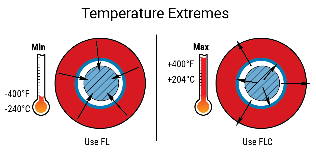
Thermal Expansion
The standard bearing I.D. options are designed for use in most industrial applications.
For temperatures below 0°F, the standard I.D. is recommended (FL series).
For extreme high temperatures, the Compensated I.D. bearing is recommended (FLC) for the increased running clearance.
- Maintains the same performance characteristics
- The thin liner allows heat to dissipate through the bearing shell
⚠ CAUTION
It is always best to inspect actual size at extreme temperatures to ensure proper running clearance.
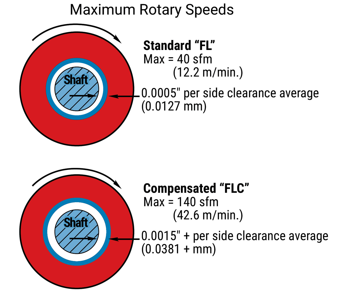
Rotary Applications
Simplicity bearings will operate very well in rotary applications if applied properly.
Stationary rotary applications do not allow the heat to be spread over an extended area. It is retained in the I.D. of the bearing limiting speed and load.
- MAX rotary speed (No lube/continuous motion)
- 40 sfm (12.2 m/min.) for standard precision I.D. clearances
- 140 sfm (42.6 m/min.) for compensated I.D. clearances
V(sfm) = 0.262 x d x RPM
d = shaft diameter (inches)
RPM = revolutions per minute - Properly maintained lubrication can increase these speeds dramatically
⚠ CAUTION
It is always best to do specific testing for rotary applications above these limits where lubrication is to be used.
Vacuums/Outgassing/Cleanrooms
Due to self-lubrication, low outgassing, and a minimum of particulate (buildup), Simplicity bearings are excellent in clean rooms and vacuums.
Testing has been done on the Frelon® materials in accordance with ASTM E-595-90 with acceptable maximums of 1.00% TML and 0.10% CVCM.
| Material | %TML | %CVCM |
|---|---|---|
| FrelonGOLD® | 0.00 | 0.00 |
| Frelon J | 0.18 | 0.01 |
TML = Total Mass Loss
CVCM = Collected Volatile Condensable Materials
Submerged Applications
Simplicity bearings will provide excellent performance in a submerged condition.
The bearings will employ the fluid as a lubricant showing increased velocities and wear life. Oils and non-salt water are especially effective.
Note: Please contact factory before specifying FrelonGOLD for submerged applications.
0-Rings
Used in standard pillow blocks and with self aligning bearings.
Nitrile Buna 70 (standard) – A good general purpose rubber that is used in 98% of applications (-65°F to 275°F (-54°C to 135°C)).
Viton (special – designate with “V”) – Used only in high temperature applications up to 400°F (up to 204°C).
Seals
Use only in the most contaminated environments.
Polymod® (standard) – A high performance polymer modified material that reduces friction of a standard buna material by 50% and increases wear life.
Polymod is a registered trademark of Polymod Technologies, Inc.
Temperature: -20°F to +212°F
Urethane (special - designate with “U”) – A moly impregnated urethane scraper that is only for the severest applications - friction is greatly increased!
Temperature: -40 to +200°F
Viton™ (special - designate with “V”) – A brand of synthetic rubber and fluoropolymer elastomer used only in high temperature applications.
Temperature: Up to +400°F
Attention: 90% of applications do not require seals when using Simplicity bearings. The liner has a natural ability to wipe particles from the shafting. Any particulate (metal, sand, etc.) that does enter the bearing will embed itself into the soft liner not scoring the shafting or locking mechanical parts.
When ordering a bearing with any internal features (seals or internal lubrication), the bearing may or may not be shipped with extra internal grooves in addition to those needed for the ordered option. Low volume orders are more likely to have additional grooves. The extra grooves will not negatively impact the performance of the bearing.
Also, internal grooves are typically an anodized surface; however, in the interest of the quickest possible delivery, the internal grooves may not be anodized.
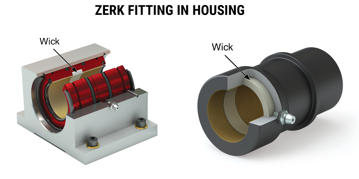
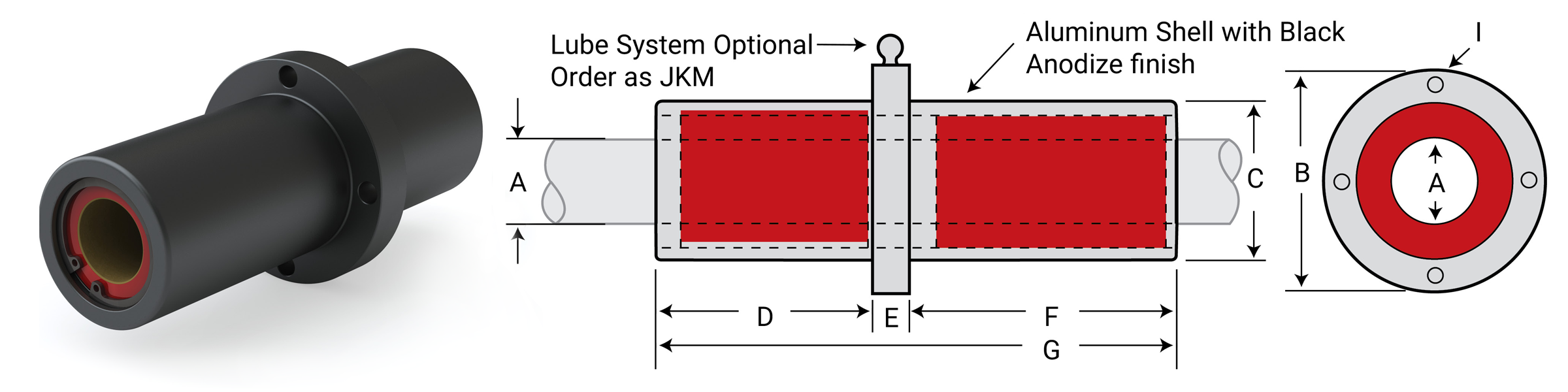
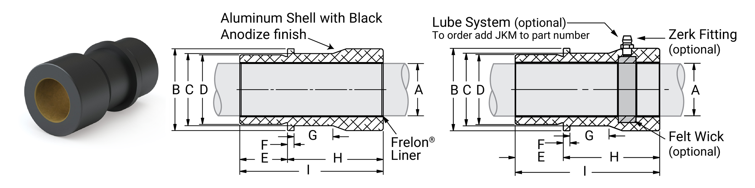
Lubrication System
Order with “JKM” modifier
Lubrication system includes:
Felt wick – Retains oil lubricants (remove when using grease lubrication). Wicks are glued in place on open bearings while they just sit in place on closed bearings.
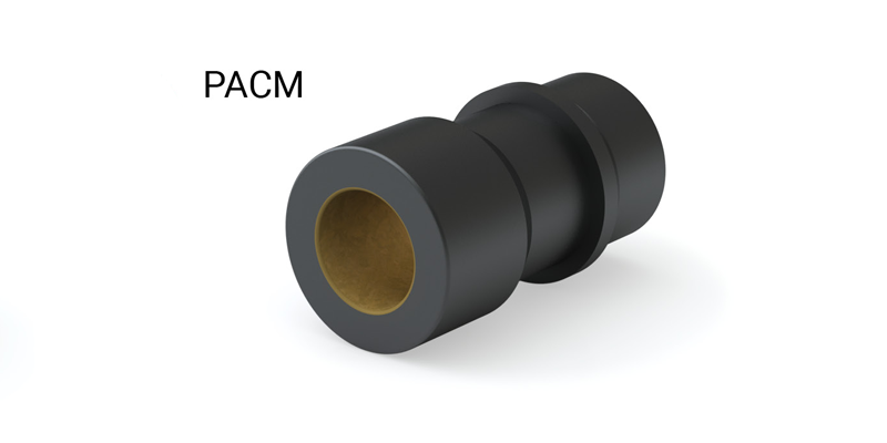
Zerk fitting – Installed into pillow block, other housing, or directly into die sets PAC, PACM. (Standard lube fitting with ¼-28 thread)
Bearing Alignment
Linear ball bearings will continue to operate in a misaligned condition, but can cause damage to the shafting and catastrophically fail.
Simplicity bearings DO NOT tolerate misalignment. They simply stop moving without any damage to the shafting. Self-aligning housings aid in misalignment – up to 1/2° from centerline.
Note: Please refer to the tables in the installation section for possible solutions to misalignment.
Applications
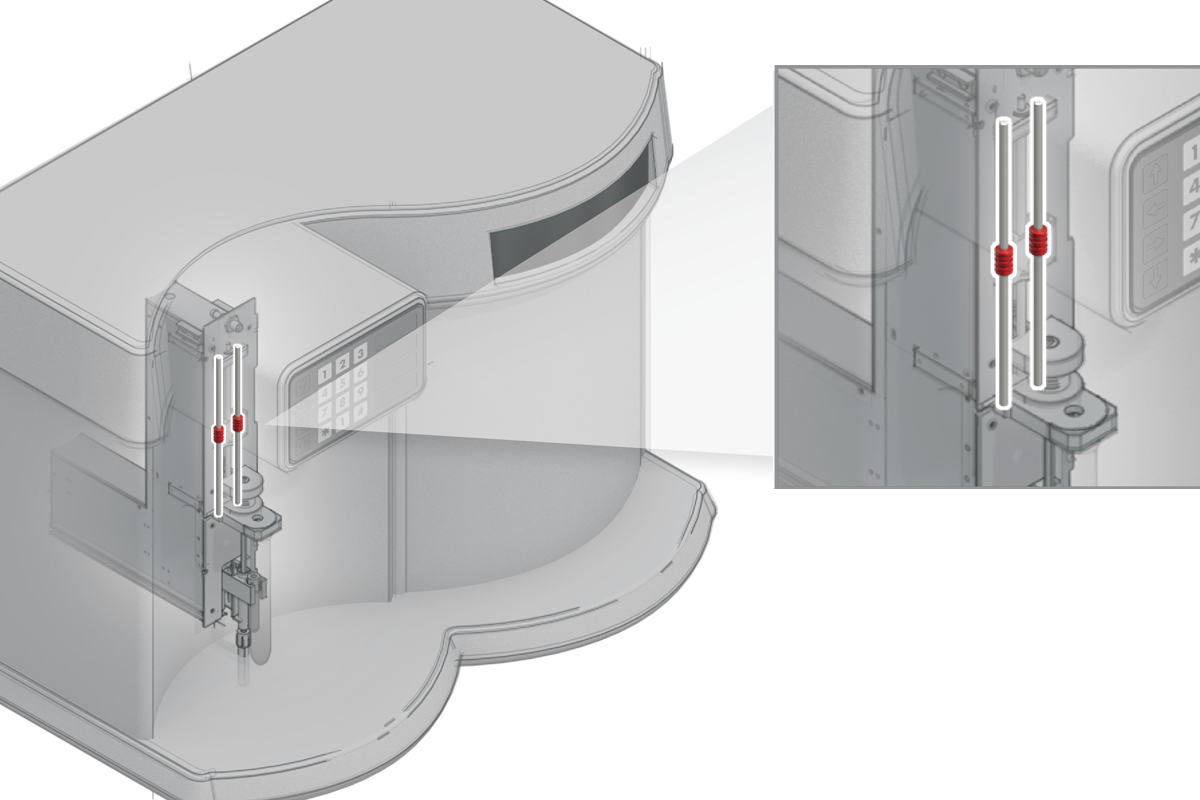
Lab Equipment
This blood analyzer utilizes Simplicity® plain bearings because they are self-lubricating and do not require additional grease, which can cause contamination.
Printing
Commercial printers, 3D printers, laser printers, and deskjets all require smooth, precise, and quiet linear motion, which Simplicity linear plain bearings provide.
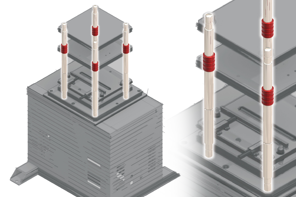
Thermoforming
Simplicity linear plain bearings operate in a wide range of temperatures, which is required when molding heated plastic sheeting in thermoforming machines.
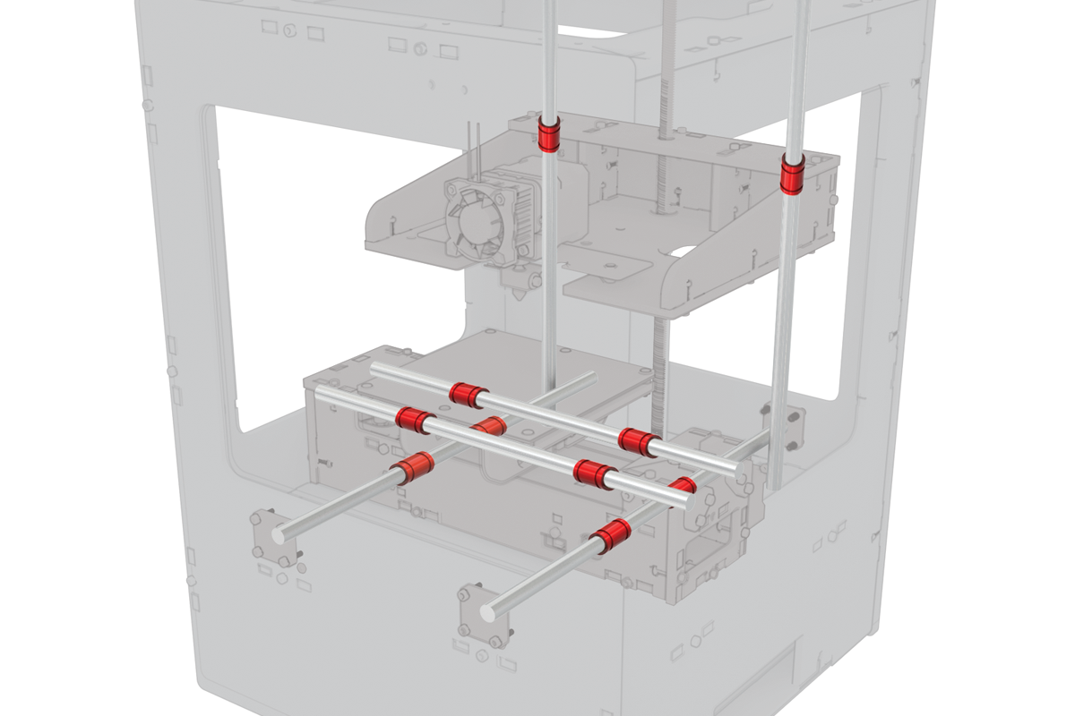
Additive Manufacturing
3D printers require smooth, repeatable linear motion, which is achieved with Frelon®-lined linear plain bearings.
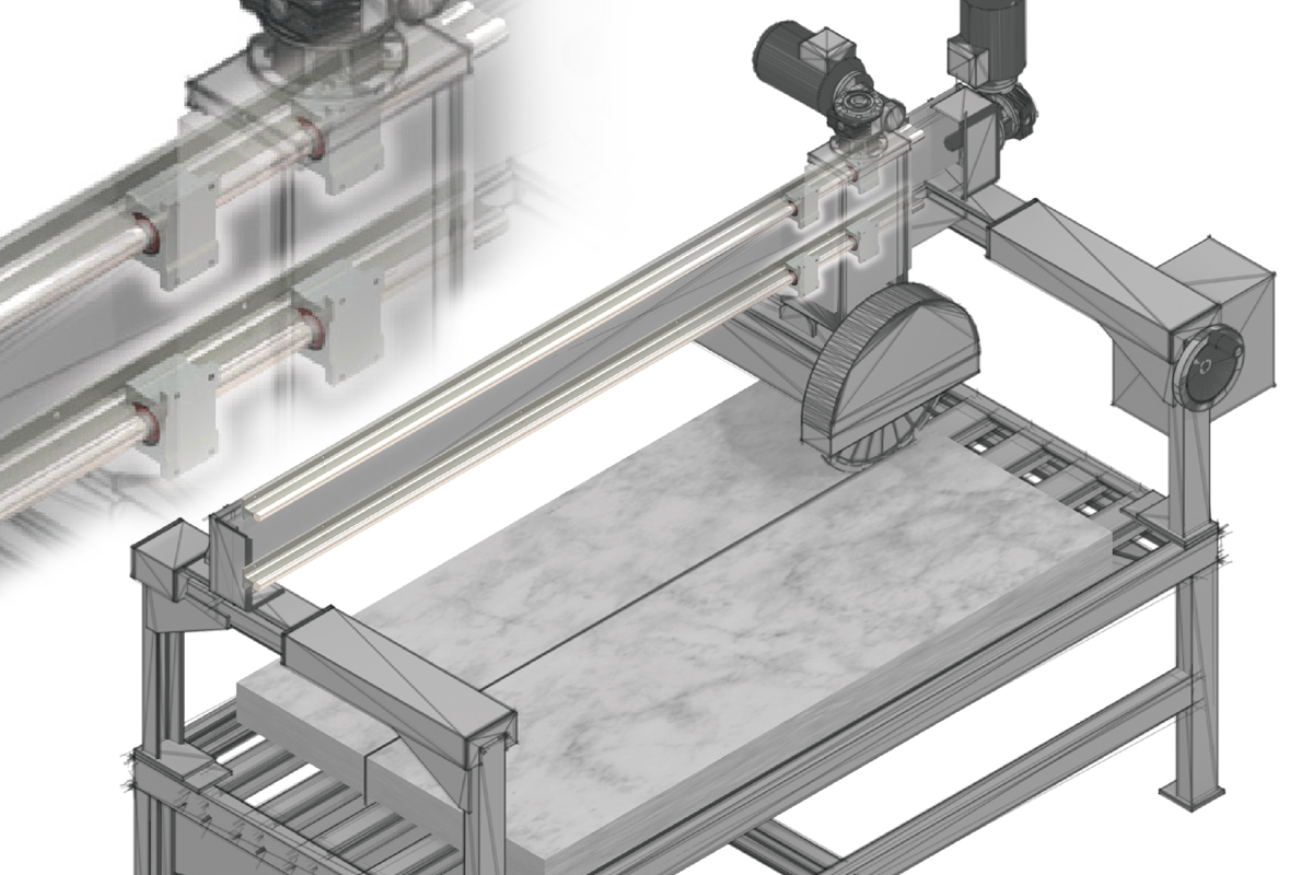
Stone Saws & Heavy Duty Cutters
Simplicity® linear plain bearings are self lubricating and excel in dirty or contaminated environments such as saws and cutters.
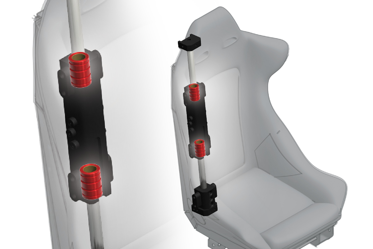
Seat Adjustment & Shock Absorption
Not all applications are easily accessible for maintenance or repair, including tough military vehicle seating. This is one reason Simplicity plain bearings, with Frelon® selflubricating liner, is the best choice. Simplicity provides long-lasting linear motion that will not catastrophically fail.
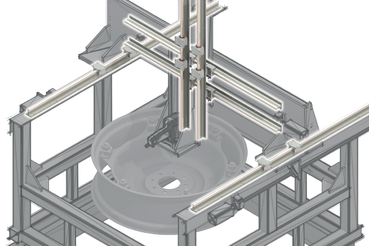
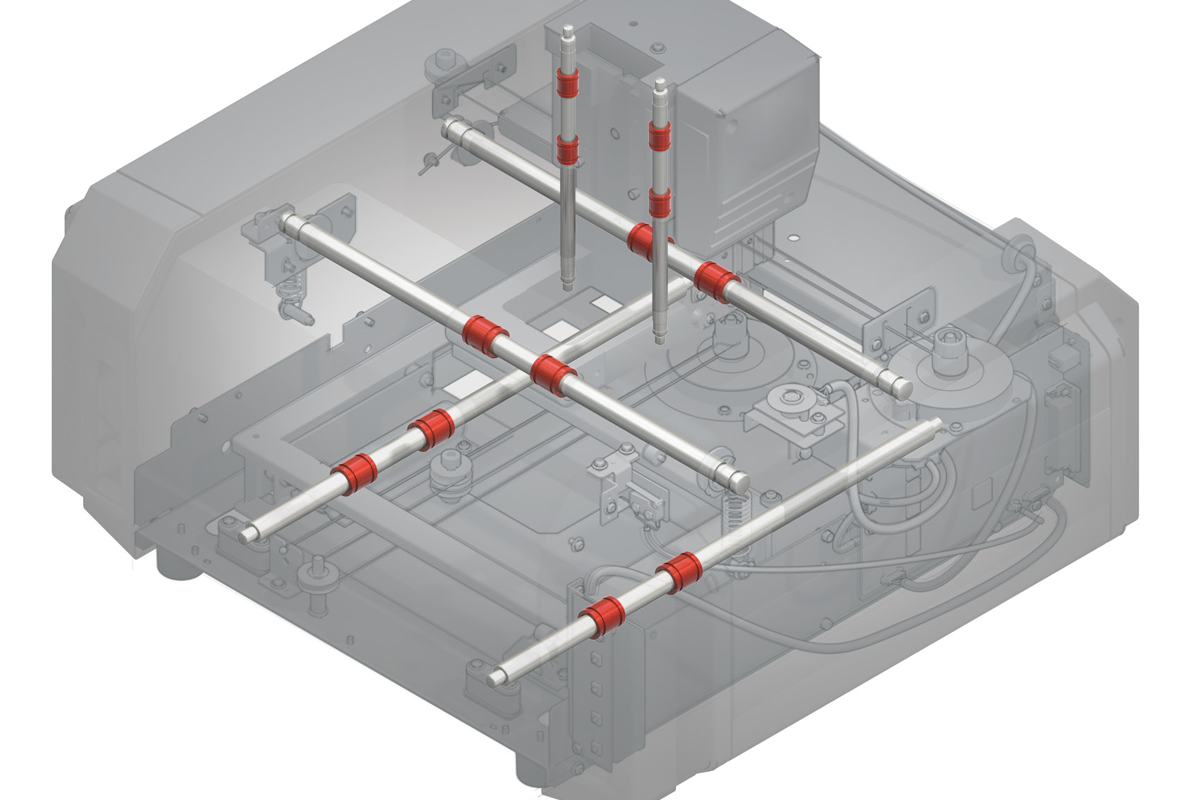
Assembly & Inspection Stations
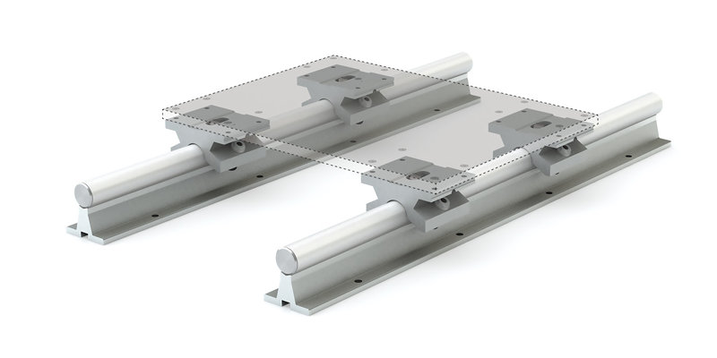
Round Shaft Technology utilizes precision round shafting as a guideway and combines linear plain or ball bearings for movement – providing a low maintenance solution in assembly stations.
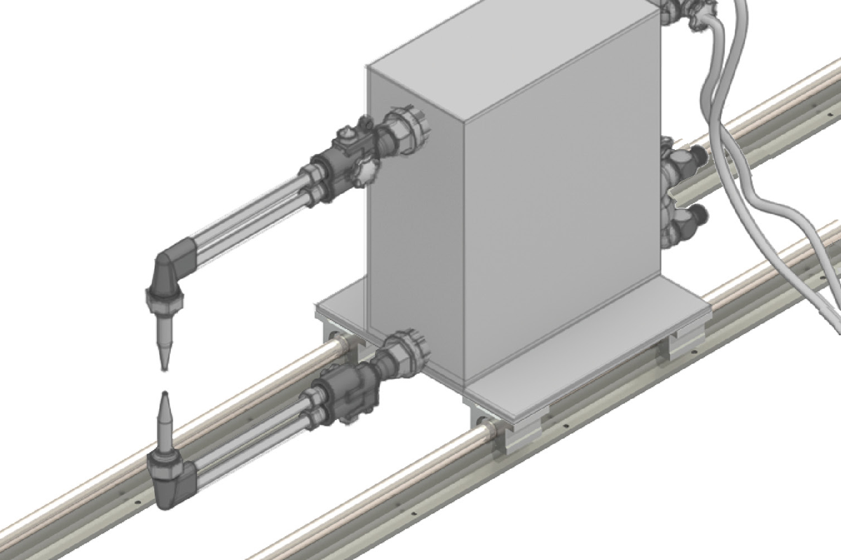
Welding Machines
Simplicity linear bearings handle loads over 700 kN (157,000 lb.) and have a high temperature range (up to 204°C). As required in welding applications, they require low maintenance in contaminated environments.
Ordering Information
Plain Bearings
| Series | O.D. Features | I.D. Features | Closed or Open Style | Bearing Shell Material | Nominal Shaft Diameter | Seal Options | Bearing Liner Material | Internal Lubrication | Special Modifications | |
| FL | A | C | N | S | 16 | - | D | E | JKM | Q |
Series
O.D. Features
Available only on FL, FM, FJ series I.D. Features
Does NOT apply to PS, PSF, PSM, PSFM Closed or Open Style
Available only on FL, FM, FJ series Bearing Shell MaterialAvailable only on FL, FM, FJ series
Nominal Shaft DiameterEnglish units in 16ths of an inch Metric units in mm Seal Options
D, DU, and DV seals available with FL08-FL32 DU seals available with FM20-FM80, FJ20-FJ120 Bearing Liner Material
Internal Lubrication
JKM available with FL08-FL64, FM12-FM80, FJ20-FJ150 Special Modifications
|
⚠ Only certified Simplicity 60 Plus Shafting provides maximum linear bearing performance.
The data and specifications in this publication have been carefully compiled and are believed to be accurate and correct. However, it is the responsibility of the user to determine and ensure the suitability of PBC Linear® products for a specific application. PBC Linear’s only obligation will be to repair or replace without charge, any defective components if returned promptly. No liability is assumed beyond such replacement. Specifications are subject to change without notice.
Plain Bearings With Housings
| Series | Closed or Open Style | Housing I.D. Features | Housings Only | Material | Nominal Shaft Diameter | Bearing I.D. Features | Seal Options | Bearing Liner Material | Internal Lubrication | Special Modifications | |
| P | N | B | E | 16 | - | C | D | E | JKM | Q | |
Series
Note: Standard Simplicity® bearings are installed in housings. Metric flange bearings do not have bearing inserts Closed or open style
Available only on FL, FM, FJ series Housing I.D. Features
Available only on P, PW, PM, SFP, DFP, SDS, DDS series
Available only on SFPM, DFPM, CFPM, SFPJ, DFPJ, CFPJ series Housings Only
Material
Nominal Shaft DiameterEnglish units in 16ths of an inch Metric units in mm Bearing I.D. Features
Seal Options
PAC and PACM available only as:
Bearing Liner Material
Internal Lubrication
Note: Zerk fitting installed into pillow block, other housing, or directly into die sets PAC & PACM. Special Modifications
|
⚠ Only certified Simplicity 60 Plus Shafting provides maximum linear bearing performance.
Simplicity Linear Plain Bearings
Dimensional Information
| Precision I.D. Series Similar to Preloaded Ball Bearing |
Compensated I.D. Series Allows additional Running Clearance |
Nominal Size in. |
B Standard O.D. |
b2 Self-Aligning FLA Crown O.D. |
C Length |
Concentric MAX |
Bearing Weight lb. |
K FLR Ret. Ring Grv. |
|||||||||
|---|---|---|---|---|---|---|---|---|---|---|---|---|---|---|---|---|---|
| Part No. | A Bearing I.D. | Part No. | A Bearing I.D. | MIN. | MAX. | MIN. | MAX. | MIN. | MAX. | ||||||||
| Closed | Open | Closed | Open | Closed | Open | Closed | Open | ||||||||||
| FL 03 | N/A | 0.1877 | 0.1884 | FLC 03 | N/A | 0.1897 | 0.1904 | 3/16 | 0.3740 | 0.3750 | 0.3725 | 0.3735 | 0.5470 | 0.5620 | 0.0010 | 0.0030 | N/A |
| FL 04 | FLN 04 | 0.2502 | 0.2511 | FLC 04 | FLCN 04 | 0.2522 | 0.2531 | 1/4 | 0.4990 | 0.5000 | 0.4975 | 0.4985 | 0.7350 | 0.7500 | 0.0010 | 0.0090 | N/A |
| FL 06 | FLN 06 | 0.3752 | 0.3761 | FLC 06 | FLCN 06 | 0.3772 | 0.3781 | 3/8 | 0.6240 | 0.6250 | 0.6225 | 0.6235 | 0.8600 | 0.8750 | 0.0010 | 0.0160 | 0.0720 |
| FL 08 | FLN 08 | 0.5002 | 0.5013 | FLC 08 | FLCN 08 | 0.5022 | 0.5033 | 1/2 | 0.8740 | 0.8750 | 0.8725 | 0.8735 | 1.2350 | 1.2500 | 0.0010 | 0.0410 | 0.0800 |
| FL 10 | FLN 10 | 0.6252 | 0.6263 | FLC 10 | FLCN 10 | 0.6272 | 0.6283 | 5/8 | 1.1240 | 1.1250 | 1.1225 | 1.1235 | 1.4850 | 1.5000 | 0.0010 | 0.0910 | N/A |
| FL 12 | FLN 12 | 0.7503 | 0.7516 | FLC 12 | FLCN 12 | 0.7533 | 0.7546 | 3/4 | 1.2490 | 1.2500 | 1.2475 | 1.2485 | 1.6100 | 1.6250 | 0.0010 | 0.1090 | 0.1710 |
| FL 16 | FLN 16 | 1.0003 | 1.0016 | FLC 16 | FLCN 16 | 1.0033 | 1.0046 | 1 | 1.5613 | 1.5625 | 1.5599 | 1.5609 | 2.2350 | 2.2500 | 0.0010 | 0.2280 | 0.1330 |
| FL 20 | FLN 20 | 1.2504 | 1.2519 | FLC 20 | FLCN 20 | 1.2544 | 1.2559 | 1-1/4 | 1.9988 | 2.0000 | 1.9974 | 1.9984 | 2.6100 | 2.6250 | 0.0010 | 0.4590 | N/A |
| FL 24 | FLN 24 | 1.5004 | 1.5019 | FLC 24 | FLCN 24 | 1.5044 | 1.5059 | 1-1/2 | 2.3738 | 2.3750 | 2.3724 | 2.3734 | 2.9850 | 3.0000 | 0.0010 | 0.7250 | N/A |
| FL 32 | FLN 32 | 2.0004 | 2.0022 | FLC 32 | FLCN 32 | 2.0054 | 2.0072 | 2 | 2.9986 | 3.0000 | 2.9973 | 2.9983 | 3.9850 | 4.0000 | 0.0010 | 1.4420 | N/A |
| FL 40 | FLN 40 | 2.5004 | 2.5022 | FLC 40 | FLCN 40 | 2.5054 | 2.5072 | 2-1/2 | 3.7484 | 3.7500 | 3.7472 | 3.7482 | 4.9850 | 5.0000 | 0.0013 | 2.8160 | N/A |
| FL 48 | FLN 48 | 3.0004 | 3.0022 | FLC 48 | FLCN 48 | 3.0064 | 3.0082 | 3 | 4.4980 | 4.5000 | 4.4970 | 4.4980 | 5.9850 | 6.0000 | 0.0015 | 4.9140 | N/A |
| FL 64 | FLN 64 | 4.0005 | 4.0026 | FLC 64 | FLCN 64 | 4.0065 | 4.0086 | 4 | 5.9980 | 6.0000 | 5.9970 | 5.9980 | 7.9850 | 8.0000 | 0.0020 | 11.8360 | N/A |
Mounting Dimensions
| Part No. | Nominal Size in. |
H Between Ret. Rings |
HA Ret. Ring Grv. Width |
HB Ret. Ring Grv. Dia. |
Truarc Ret. Ring Part No. | J Between O’Ring Grvs. |
JA O’Ring Grv. Width |
JB O’Ring Grv. Dia. |
Parker O’Ring Part No. | H2 FLR Between Rings |
H3 FLR Ringe Edge |
|
|---|---|---|---|---|---|---|---|---|---|---|---|---|
| Closed | Open | |||||||||||
| FL 03 | N/A | 3/16 | 0.375 | 0.030 | 0.352 | N 5100-37 | N/A | N/A | N/A | N/A | N/A | N/A |
| FL 04 | FLN 04 | 1/4 | 0.437 | 0.041 | 0.467 | N 5100-50 | 0.125 | 0.080 | 0.399 | 2-010 | N/A | N/A |
| FL 06 | FLN 06 | 3/8 | 0.562 | 0.041 | 0.587 | N 5100-62 | 0.187 | 0.080 | 0.524 | 2-012 | 0.711/0.701 | 0.112 |
| FL 08 | FLN 08 | 1/2 | 0.875 | 0.048 | 0.820 | N 5100-87 | 0.250 | 0.125 | 0.712 | 2-113 | 1.042/1.032 | 0.135 |
| FL 10 | FLN 10 | 5/8 | 1.000 | 0.058 | 1.060 | N 5100-112 | 0.312 | 0.125 | 0.962 | 2-117 | N/A | N/A |
| FL 12 | FLN 12 | 3/4 | 1.062 | 0.058 | 1.177 | N 5100-125 | 0.312 | 0.125 | 1.087 | 2-119 | 1.281/1.271 | 0.220 |
| FL 16 | FLN 16 | 1 | 1.625 | 0.070 | 1.471 | N 5100-156 | 0.500 | 0.125 | 1.399 | 2-123 | 1.895/1.885 | 0.239 |
| FL 20 | FLN 20 | 1-1/4 | 1.875 | 0.070 | 1.889 | N 5100-200 | 0.625 | 0.125 | 1.837 | 2-129 | N/A | N/A |
| FL 24 | FLN 24 | 1-1/2 | 2.250 | 0.089 | 2.241 | N 5100-237 | 0.750 | 0.162 | 2.152 | 2-225 | N/A | N/A |
| FL 32 | FLN 32 | 2 | 3.000 | 0.105 | 2.839 | N 5100-300 | 1.000 | 0.189 | 2.775 | 2-229 | N/A | N/A |
| FL 40 | FLN 40 | 2-1/2 | 3.750 | 0.123 | 3.553 | N 5100-375 | 1.250 | 0.250 | 3.408 | 2-340 | N/A | N/A |
| FL 48 | FLN 48 | 3 | 4.500 | 0.123 | 4.309 | N 5100-450 | 1.500 | 0.287 | 4.158 | 2-346 | N/A | N/A |
| FL 64 | FLN 64 | 4 | 6.000 | 0.145 | 5.748 | N 5100-600 | 2.000 | 0.287 | 5.660 | 2-356 | N/A | N/A |
Note: FLR is only available on FL06, FL08, FL12 and FL16.
Linear Plain Bearings FL & FLN
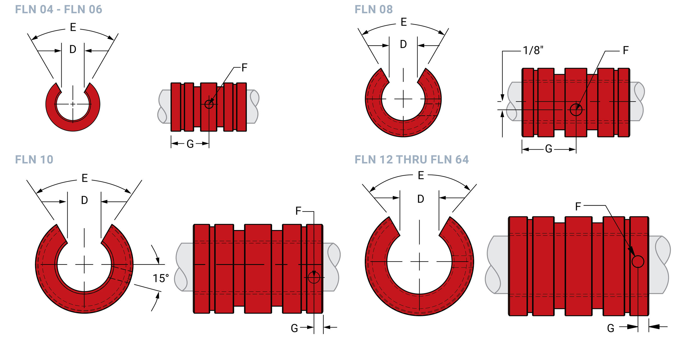
Open Dimensional Information
| Part No. | Nominal Size in. |
D Slot Wide MIN. |
E Slot Angle |
F Retaining Hole Dia. |
G Retaining Hole Locate in. |
Bearing Weight lb. |
|
|---|---|---|---|---|---|---|---|
| Precision | Compensated | ||||||
| FLN 04 | FLCN 04 | 1/4 | 0.188 | 60° | 0.094 | 3/8 | 0.008 |
| FLN 06 | FLCN 06 | 3/8 | 0.250 | 60° | 0.094 | 7/16 | 0.013 |
| FLN 08 | FLCN 08 | 1/2 | 0.313 | 60° | 0.136 | 5/8 | 0.034 |
| FLN 10 | FLCN 10 | 5/8 | 0.375 | 60° | 0.136 | 1/8 | 0.072 |
| FLN 12 | FLCN 12 | 3/4 | 0.438 | 60° | 0.136 | 1/8 | 0.091 |
| FLN 16 | FLCN 16 | 1 | 0.563 | 60° | 0.136 | 1/8 | 0.184 |
| FLN 20 | FLCN 20 | 1-1/4 | 0.625 | 60° | 0.201 | 3/16 | 0.381 |
| FLN 24 | FLCN 24 | 1-1/2 | 0.750 | 60° | 0.201 | 3/16 | 0.603 |
| FLN 32 | FLCN 32 | 2 | 1.000 | 60° | 0.265 | 5/16 | 1.192 |
| FLN 40 | FLCN 40 | 2-1/2 | 1.250 | 60° | 0.265 | 5/16 | 2.334 |
| FLN 48 | FLCN 48 | 3 | 1.500 | 60° | 0.265 | 5/16 | 4.080 |
| FLN 64 | FLCN 64 | 4 | 2.000 | 60° | 0.265 | 5/16 | 9.870 |
Note: All other dimensions same as closed bearing. FrelonGOLD® and Frelon® J are registered trademarks of PBC Linear®.
Load & Speed Data
| Part No. | Effective Surface Area SQ. in. |
MAX. Static Load lb. Frelon |
|
|---|---|---|---|
| GOLD | J & W | ||
| FL 03 | 0.110 | 220 | 100 |
| FL 04 | 0.200 | 600 | 300 |
| FL 06 | 0.340 | 1020 | 510 |
| FL 08 | 0.650 | 1950 | 975 |
| FL 10 | 0.980 | 2940 | 1470 |
| FL 12 | 1.270 | 3810 | 1905 |
| FL 16 | 2.350 | 7050 | 3525 |
| FL 20 | 3.430 | 10830 | 5415 |
| FL 24 | 4.700 | 14100 | 7050 |
| FL 32 | 8.350 | 25050 | 12525 |
| FL40 | 13.000 | 39000 | 19500 |
| FL 48 | 18.800 | 56400 | 28200 |
| FL 64 | 33.500 | 100500 | 50250 |
Note:
MAX PV (ft./min. * psi)
FrelonGOLD = 20000 PV Frelon J = 10000 PV
MAX Speed Running Dry (ft./min.)
FrelonGOLD = 300 sfm
Frelon J = 140 sfm
MAX Speed Running with Lubrication (ft./min.)
FrelonGOLD = 825 sfm
Frelon J = 400 sfm
⚠ Only certified Simplicity 60 Plus Shafting provides maximum linear bearing performance.
Simplicity Pillow Blocks
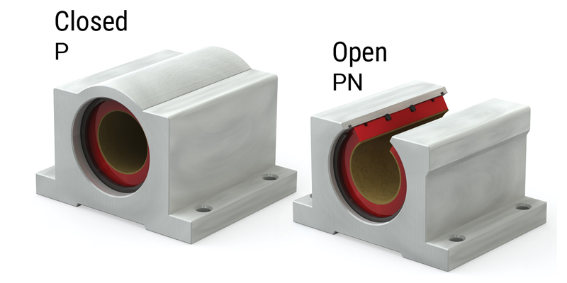
Plain Bearings – Closed Pillow Blocks P
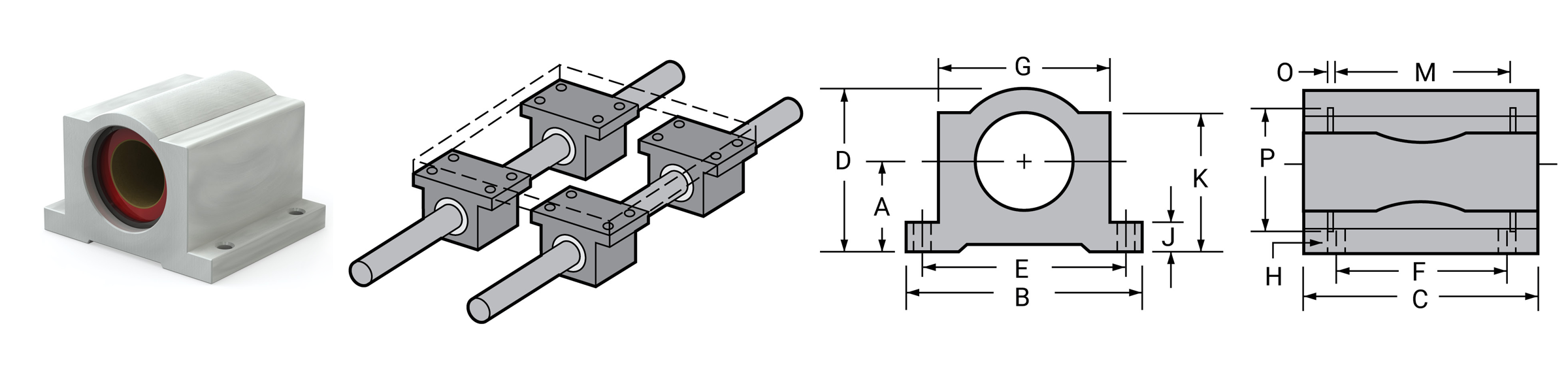
| Part No. | Nom. Brg. I.D. in. |
A Centerline +/- 0.001 |
B Width |
C Length |
D Height |
E +/- 0.010 |
F +/- 0.010 |
G Body Width |
H | J Flange Thick |
k | M Grv. Space |
O Grv. Width |
P Grv. Dia. |
Retaining Ring Part No. | MAX Static Load lb. FRELON® |
Assem WT. lb. |
|||
|---|---|---|---|---|---|---|---|---|---|---|---|---|---|---|---|---|---|---|---|---|
| Precision | Compensated | Bolt | Hole | GOLD | J & W | |||||||||||||||
| P 04 | P 04C | 1/4 | 0.437 | 1.625 | 1.19 | 0.813 | 1.312 | 0.750 | 1.000 | #6 | 5/32" | 0.188 | 0.750 | 0.750 | 0.039 | 0.532 | 6010026 | 600 | 300 | 0.099 |
| P 06 | P 06C | 3/8 | 0.500 | 1.750 | 1.31 | 0.938 | 1.437 | 0.875 | 1.125 | #6 | 5/32" | 0.188 | 0.875 | 0.875 | 0.039 | 0.665 | 6010027 | 1020 | 510 | 0.129 |
| P 08 | P 08C | 1/2 | 0.687 | 2.000 | 1.69 | 1.250 | 1.688 | 1.000 | 1.375 | #6 | 5/32" | 0.250 | 1.125 | 1.250 | 0.046 | 0.931 | 6010028 | 1950 | 975 | 0.250 |
| P 10 | P 10C | 5/8 | 0.875 | 2.500 | 1.94 | 1.625 | 2.125 | 1.125 | 1.750 | #8 | 3/16" | 0.281 | 1.438 | 1.500 | 0.056 | 1.197 | 6010029 | 2940 | 1470 | 0.500 |
| P 12 | P 12C | 3/4 | 0.937 | 2.750 | 2.06 | 1.750 | 2.375 | 1.250 | 1.875 | #8 | 3/16" | 0.313 | 1.563 | 1.625 | 0.056 | 1.330 | 6010030 | 3710 | 1905 | 0.580 |
| P 16 | P 16C | 1 | 1.187 | 3.250 | 2.81 | 2.188 | 2.875 | 1.750 | 2.375 | #10 | 7/32" | 0.375 | 1.938 | 2.250 | 0.068 | 1.671 | 6010031 | 7050 | 3525 | 1.000 |
| P 20 | P 20C | 1-1/4 | 1.500 | 4.000 | 3.63 | 2.813 | 3.500 | 2.000 | 3.000 | #10 | 7/32" | 0.438 | 2.500 | 2.625 | 0.068 | 2.122 | 6010032 | 10290 | 5145 | 2.000 |
| P 24 | P 24C | 1-1/2 | 1.750 | 4.750 | 4.00 | 3.250 | 4.125 | 2.500 | 3.500 | 1/4" | 9/32" | 0.500 | 2.875 | 3.000 | 0.086 | 2.519 | 6010033 | 14100 | 7050 | 3.000 |
| P 32 | P 32C | 2 | 2.125 | 6.000 | 5.00 | 4.063 | 5.250 | 3.250 | 4.500 | 3/8" | 13/32" | 0.625 | 3.625 | 4.000 | 0.103 | 3.182 | 6010034 | 25050 | 12525 | 6.500 |
Notes:
(1) Standard, pre-assembled pillow blocks include self-aligning housing and precision bearing.
(2) All standard pillow blocks use standard FL series bearings.
(3) Straight bore, pre-assembled pillow blocks use standard FL series bearings.
Plain Bearings – Open Pillow Blocks PN
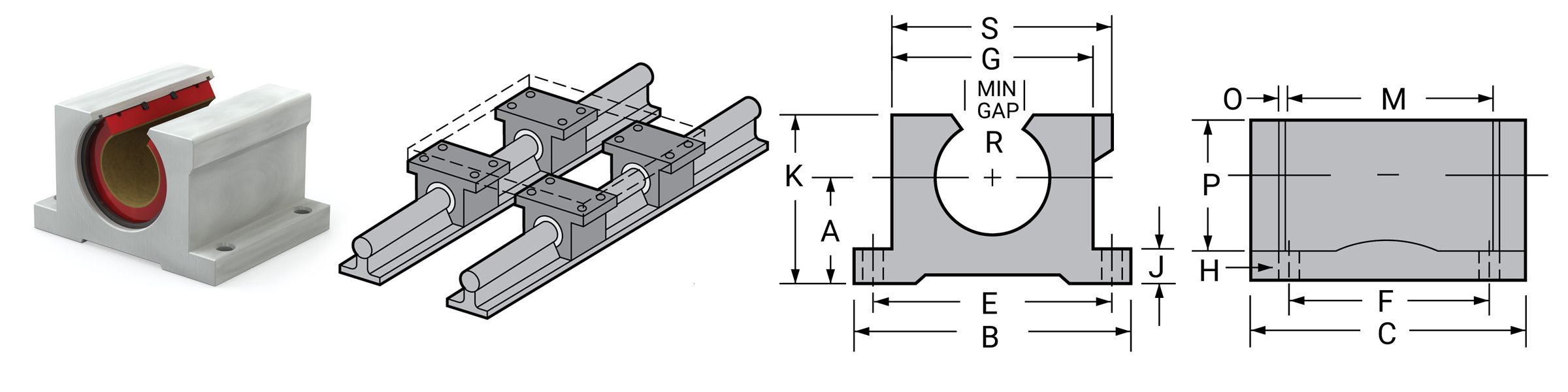
| Part No. | Nom. Brg. I.D. in. |
A Centerline +/- 0.001 |
B Width |
C Length |
E +/- 0.010 |
F +/- 0.010 |
G Body Width |
H | J Flange Thick |
K Height |
M Grv. Space |
O Grv. Width |
P Grv. Dia. |
R Min. Open |
Retaining Ring Part No. | MAX Static Load lb. FRELON® |
Assem WT. lb. |
S Overall width |
|||
|---|---|---|---|---|---|---|---|---|---|---|---|---|---|---|---|---|---|---|---|---|---|
| Precision | Compensated | Bolt | Hole | GOLD | J & W | ||||||||||||||||
| PN 08 | PN 08C | 1/2 | 0.687 | 2.000 | 1.50 | 1.688 | 1.000 | 1.375 | #6 | 5/32" | 0.250 | 1.125 | 1.250 | 0.046 | 0.931 | 0.313 | 6010035 | 1950 | 975 | 0.250 | 1.438 |
| PN 10 | PN 10C | 5/8 | 0.875 | 2.500 | 1.75 | 2.125 | 1.125 | 1.750 | #8 | 3/16" | 0.281 | 1.438 | 1.500 | 0.056 | 1.197 | 0.375 | 6010036 | 2940 | 1470 | 0.500 | 1.813 |
| PN 12 | PN 12C | 3/4 | 0.937 | 2.750 | 1.88 | 2.375 | 1.250 | 18.75 | #8 | 3/16" | 0.313 | 1.563 | 1.625 | 0.056 | 1.330 | 0.438 | 6010037 | 3710 | 1905 | 0.580 | 1.938 |
| PN 16 | PN 16C | 1 | 1.187 | 3.250 | 2.63 | 2.875 | 1.750 | 2.375 | #10 | 7/32" | 0.375 | 1.938 | 2.250 | 0.068 | 1.671 | 0.563 | 6010038 | 7050 | 3525 | 1.000 | 2.438 |
| PN 20 | PN 20C | 1-1/4 | 1.500 | 4.000 | 3.38 | 3.500 | 2.000 | 3.000 | #10 | 7/32" | 0.438 | 2.500 | 2.625 | 0.068 | 2.122 | 0.625 | 6010039 | 10290 | 5145 | 2.000 | 3.125 |
| PN 24 | PN 24C | 1-1/2 | 1.750 | 4.750 | 3.75 | 4.125 | 25.00 | 3.500 | 1/4" | 9/32" | 0.500 | 2.875 | 3.000 | 0.086 | 2.519 | 0.750 | 6010040 | 14100 | 7050 | 3.000 | 3.625 |
| PN 32 | PN 32C | 2 | 2.125 | 6.000 | 4.75 | 5.250 | 3.250 | 4.500 | 3/8" | 13/32" | 0.625 | 3.625 | 4.000 | 0.103 | 3.182 | 1.000 | 6010041 | 25050 | 12525 | 6.500 | 4.688 |
Notes:
(1) Standard, pre-assembled pillow blocks include self-aligning housing and precision bearing.
(2) All standard pillow blocks use standard FL series bearings.
⚠ Only certified Simplicity 60 Plus Shafting provides maximum linear bearing performance.
Simplicity Twin Pillow Blocks
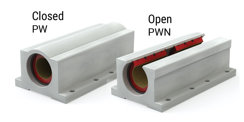
Plain Bearings – Closed Twin Pillow Blocks PW
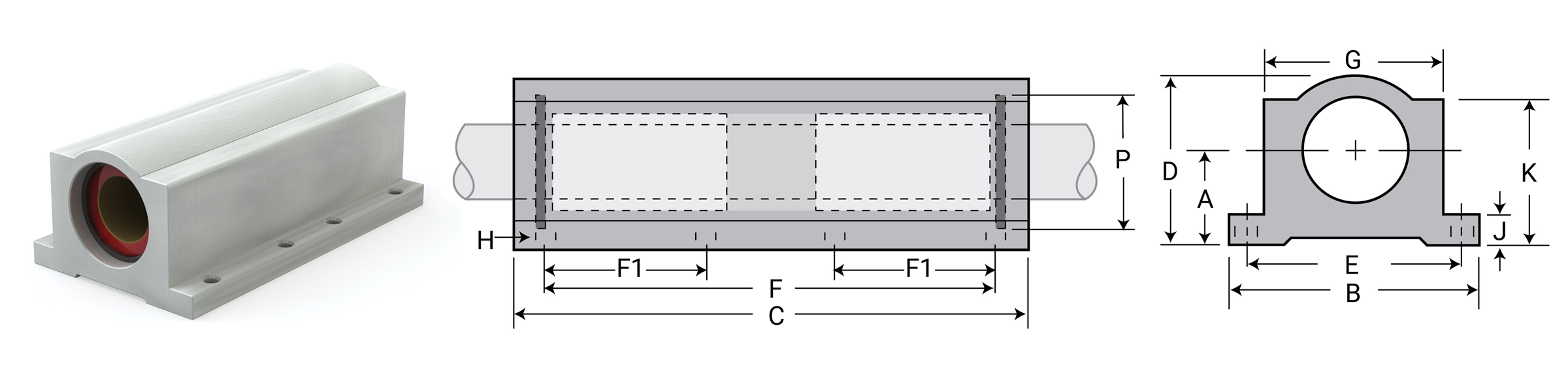
| Part No. | Nom. Brg. I.D. in. |
A Centerline +/- 0.001 |
B Width |
C Length |
D Height |
E +/- 0.010 |
F +/- 0.010 |
F1 +/- 0.010 |
G Body Width |
H | J Flange Thick |
K | P Grv. Dia. |
Retaining Ring Part No. | MAX Static Load lb. FRELON® |
Assem WT. lb. |
|||
|---|---|---|---|---|---|---|---|---|---|---|---|---|---|---|---|---|---|---|---|
| Precision | Compensated | Bolt | Hole | GOLD | J & W | ||||||||||||||
| PW 04 | PW 04C | 1/4 | 0.437 | 1.625 | 2.500 | 0.813 | 1.3120 | 2.0000 | 0.750 | 1.000 | #6 | 5/32" | 0.188 | 0.750 | 0.532 | 6010026 | 1200 | 600 | 0.197 |
| PW 06 | PW 06C | 3/8 | 0.500 | 1.750 | 2.750 | 0.938 | 1.4370 | 2.2500 | 0.875 | 1.125 | #6 | 5/32" | 0.188 | 0.875 | 0.665 | 6010027 | 2040 | 1020 | 0.258 |
| PW 08 | PW 08C | 1/2 | 0.687 | 2.000 | 3.500 | 1.250 | 1.6880 | 2.5000 | 1.000 | 1.375 | #6 | 5/32" | 0.250 | 1.125 | 0.931 | 6010028 | 3900 | 1950 | 0.500 |
| PW 10 | PW 10C | 5/8 | 0.875 | 2.500 | 4.000 | 1.625 | 2.1250 | 3.0000 | 1.125 | 1.750 | #8 | 3/16" | 0.281 | 1.438 | 1.197 | 6010029 | 5880 | 2940 | 1.000 |
| PW 12 | PW 12C | 3/4 | 0.937 | 2.750 | 4.500 | 1.750 | 2.3750 | 3.5000 | 1.250 | 1.875 | #8 | 3/16" | 0.313 | 1.563 | 1.330 | 6010030 | 7620 | 3810 | 1.125 |
| PW 16 | PW 16C | 1 | 1.187 | 3.250 | 6.000 | 2.188 | 2.8750 | 4.5000 | 1.750 | 2.375 | #10 | 7/32" | 0.375 | 1.938 | 1.671 | 6010031 | 14100 | 7050 | 2.188 |
| PW 20 | PW 20C | 1-1/4 | 1.500 | 4.000 | 7.500 | 2.813 | 3.5000 | 5.5000 | 2.000 | 3.000 | #10 | 7/32" | 0.438 | 2.500 | 2.122 | 6010032 | 20580 | 10290 | 4.250 |
| PW 24 | PW 24C | 1-1/2 | 1.750 | 4.750 | 9.000 | 3.250 | 4.1250 | 6.5000 | 2.500 | 3.500 | 1/4" | 9/32" | 0.500 | 2.875 | 2.519 | 6010033 | 28200 | 14100 | 6.375 |
| PW 32 | PW 32C | 2 | 2.125 | 6.000 | 10.000 | 4.063 | 5.2500 | 8.2500 | 3.250 | 4.500 | 3/8" | 13/32" | 0.625 | 3.625 | 3.182 | 6010034 | 50100 | 25050 | 13.500 |
Notes:
(1) Standard, pre-assembled pillow blocks include self-aligning housing and precision bearing.
(2) All standard pillow blocks use standard FL series bearings.
(3) Twin Closed Pillow Blocks use a spacer to separate the bearings.
(4) Twin pillow blocks, closed, with no seal option: Use two standard bearings, based on compensated or standard option.
(5) Twin pillow blocks, closed, with double seal option: Use two single seal bearings.
Plain Bearings – Open Twin Pillow Blocks PWN
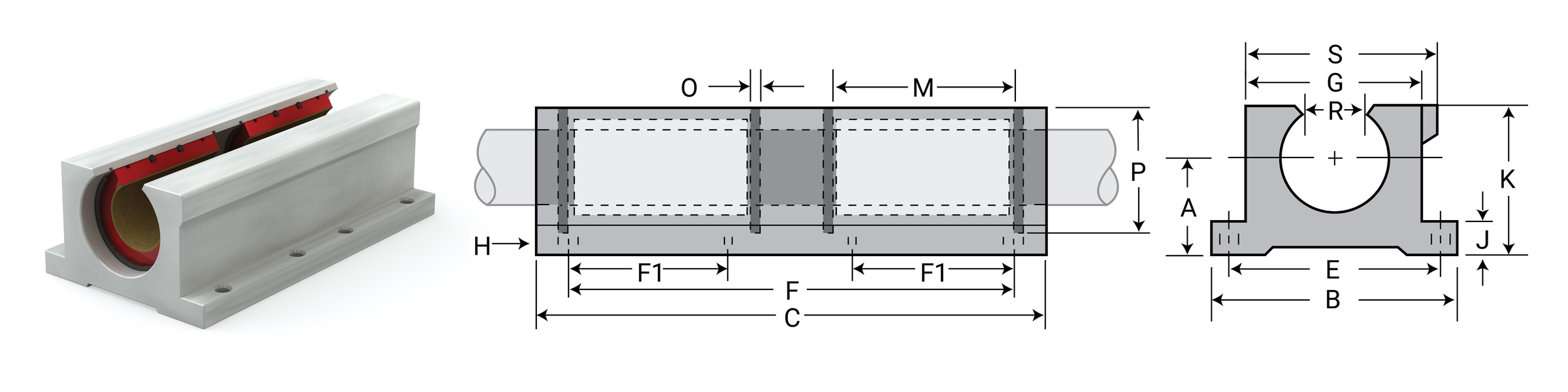
| Part No. | Nom. Brg. I.D. in. |
A Centerline +/- 0.001 |
B Width |
C Length |
E +/- 0.010 |
F +/- 0.010 |
F1 +/- 0.010 |
G Body Width |
H | J Flange Thick |
K Height |
M Grv. Space |
O Grv. Width |
P Grv. Dia. |
R Min. Open |
Retaining Ring Part No. | MAX Static Load lb. FRELON® |
Assem WT. lb. |
S Overall width |
|||
|---|---|---|---|---|---|---|---|---|---|---|---|---|---|---|---|---|---|---|---|---|---|---|
| Precision | Compensated | Bolt | Hole | GOLD | J & W | |||||||||||||||||
| PWN 08 | PWN 08C | 1/2 | 0.687 | 2.000 | 3.500 | 1.688 | 2.500 | 1.000 | 1.375 | #6 | 5/32" | 0.250 | 1.125 | 1.250 | 0.046 | 0.931 | 0.313 | 6010035 | 3900 | 1950 | 0.400 | 1.438 |
| PWN 10 | PWN 10C | 5/8 | 0.875 | 2.500 | 4.000 | 2.125 | 3.000 | 1.125 | 1.750 | #8 | 3/16" | 0.281 | 1.438 | 1.500 | 0.056 | 1.197 | 0.375 | 6010036 | 5880 | 2940 | 0.910 | 1.813 |
| PWN 12 | PWN 12C | 3/4 | 0.937 | 2.750 | 4.500 | 2.375 | 3.500 | 1.250 | 1.875 | #8 | 3/16" | 0.313 | 1.563 | 1.625 | 0.056 | 1.330 | 0.438 | 6010037 | 7620 | 3810 | 1.060 | 1.938 |
| PWN 16 | PWN 16C | 1 | 1.187 | 3.250 | 6.000 | 2.875 | 4.500 | 1.750 | 2.375 | #10 | 7/32" | 0.375 | 1.938 | 2.250 | 0.068 | 1.671 | 0.563 | 6010038 | 14100 | 7050 | 1.970 | 2.438 |
| PWN 20 | PWN 20C | 1-1/4 | 1.500 | 4.000 | 7.500 | 3.500 | 5.500 | 2.000 | 3.000 | #10 | 7/32" | 0.438 | 2.500 | 2.625 | 0.068 | 2.122 | 0.625 | 6010039 | 20580 | 10290 | 3.725 | 3.125 |
| PWN 24 | PWN 24C | 1-1/2 | 1.750 | 4.750 | 9.000 | 4.125 | 6.500 | 2.500 | 3.500 | 1/4" | 9/32" | 0.500 | 2.875 | 3.000 | 0.086 | 2.519 | 0.750 | 6010040 | 28200 | 14100 | 5.800 | 3.625 |
| PWN 32 | PWN 32C | 2 | 2.125 | 6.000 | 10.000 | 5.250 | 8.250 | 3.250 | 4.500 | 3/8" | 13/32" | 0.625 | 3.625 | 4.000 | 0.103 | 3.182 | 1.000 | 6010041 | 50100 | 25050 | 12.125 | 4.688 |
Notes:
(1) Standard, pre-assembled pillow blocks include self-aligning housing and precision bearing.
(2) All standard pillow blocks use standard FL series bearings.
(3) Twin pillowblocks, open, with no seal option: Use two standard open bearings, based on compensated or standard option.
(4) Twin pillowblocks, open, with double seal option: Use two double seal bearings.
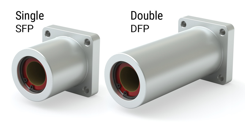
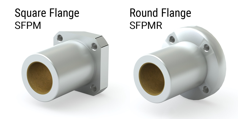
Simplicity Flange Mounts
Flange Mounts SFP
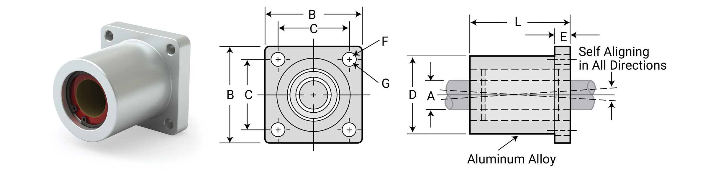
Dimensional Information
| Part No. | A Nominal Bearing Size |
B Flange Square |
C Hole Spacing |
D Barrel Dia. |
E Flange Length |
F Bolt Size |
G Hole Size |
L Length Overall |
MAX Static Load lb. FRELON® |
Assembly Weight lb. |
||
|---|---|---|---|---|---|---|---|---|---|---|---|---|
| Precision | Compensated | GOLD | J & W | |||||||||
| SFP 06 | SFP 06 C | 3/8" | 1.25 | 1.00 | 0.875 | 0.188 | #4 | 0.125 | 1.31 | 1020 | 510 | 0.070 |
| SFP 08 | SFP 08 C | 1/2" | 1.63 | 1.25 | 1.25 | 0.250 | #8 | 0.187 | 1.687 | 1950 | 975 | 0.175 |
| SFP 12 | SFP 12 C | 3/4" | 2.38 | 1.75 | 1.75 | 0.375 | #10 | 0.219 | 2.067 | 2940 | 1470 | 0.463 |
| SFP 16 | SFP 16 C | 1" | 2.75 | 2.125 | 2.25 | 0.500 | 1/4" | 0.281 | 2.812 | 3810 | 1905 | 1.206 |
| SFP 20 | SFP 20 C | 1 1/4" | 3.88 | 3.00 | 2.62 | 0.625 | 3/8" | 0.386 | 3.625 | 10830 | 5415 | 1.830 |
Notes:
(1) All standard, pre-assembled SFP assemblies include a self-aligning housing and standard FL bearings - allowing the bearing to self-align.
(2) SFPB assemblies include a straight bore housing and standard FL bearings - allowing for a more rigid fit.
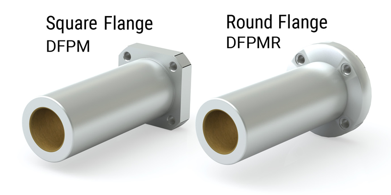
Flange Mounts DFP
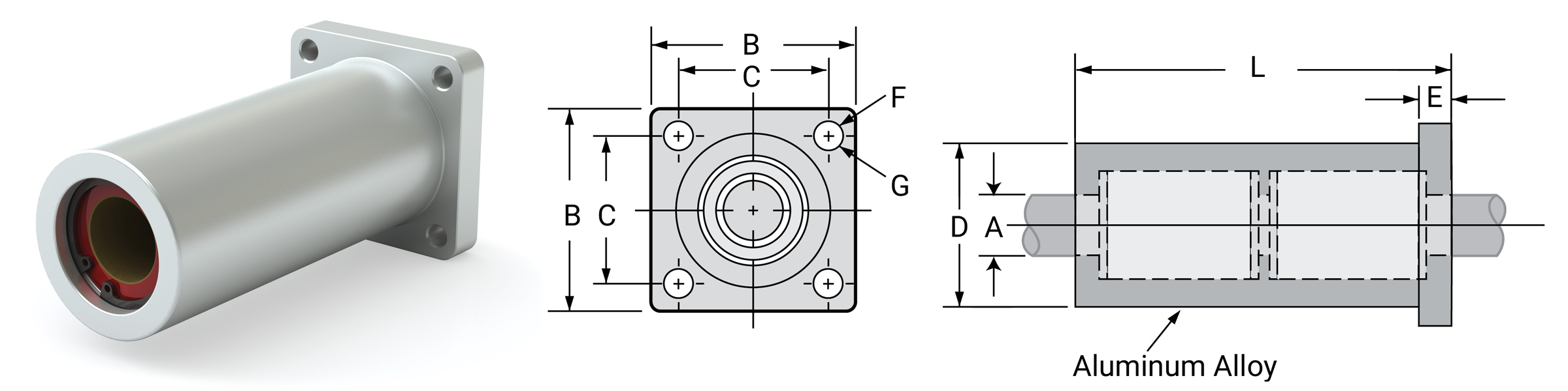
Dimensional Information
| Part No. | A Nominal Bearing Size |
B Flange Square |
C Hole Spacing |
D Barrel Dia. |
E Flange Length |
F Bolt Size |
G Hole Size |
L Length Overall |
MAX Static Load lb. FRELON® |
Assembly Weight lb. |
||
|---|---|---|---|---|---|---|---|---|---|---|---|---|
| Precision | Compensated | GOLD | J & W | |||||||||
| DFP 08 | DFP 08 C | 1/2" | 1.63 | 1.25 | 1.25 | 0.250 | #8 | 0.187 | 3.375 | 3900 | 1950 | 0.325 |
| DFP 12 | DFP 12 C | 3/4" | 2.38 | 1.75 | 1.75 | 0.375 | #10 | 0.219 | 4.188 | 5880 | 2940 | 0.825 |
| DFP 16 | DFP 16 C | 1" | 2.75 | 2.125 | 2.25 | 0.500 | 1/4" | 0.281 | 5.625 | 7620 | 3810 | 1.750 |
Notes:
(1) All standard, pre-assembled DFP assemblies include a self-aligning housing and standard FL bearings - allowing the bearing to self-align.
(2) Straight bore DFPB assemblies include a straight bore housing and standard FL bearings - allowing for a more rigid fit.
⚠ Only certified Simplicity 60 Plus Shafting provides maximum linear bearing performance.
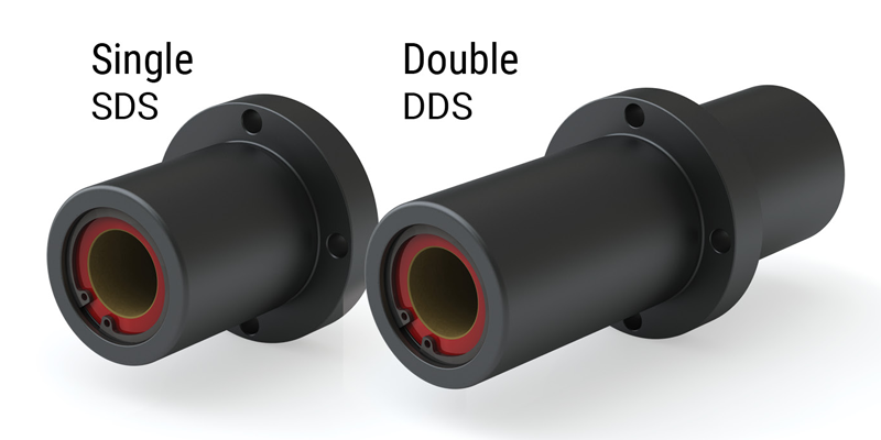
Simplicity Die Set Flange Mounts
Flange Mounts SDS
Dimensional Information
| Part No. | A Nominal Bearing Size |
B Flange O.D. |
C Barrel Dia. |
D Pilot Dia. |
E Pilot Length |
F Flange Length |
G Head Length |
H Overall Length |
I Mounting Holes 4 Places |
MAX Static Load lb. FRELON® |
Assembly Weight lb. |
||||||
|---|---|---|---|---|---|---|---|---|---|---|---|---|---|---|---|---|---|
| Precision | Compensated | Min | Max | Min | Max | Bolt Size | Hole Size | Circle | GOLD | J & W | |||||||
| SDSZ16 | SDSZ16C | 1" | 3.00 | 2.098 | 2.100 | 1.4995 | 1.500 | 0.875 | 0.562 | 2.500 | 3.927 | 1/4" | 0.281 | 2.550 | 7050 | 3525 | 0.941 |
| SDSZ20 | SDSZ20C | 1-1/4" | 3.50 | 2.598 | 2.600 | 1.7495 | 1.750 | 1.125 | 0.750 | 3.000 | 4.875 | 1/4" | 0.281 | 3.050 | 10290 | 5145 | 1.852 |
| SDSZ24 | SDSZ24C | 1-1/2" | 4.25 | 2.998 | 3.000 | 1.9990 | 2.000 | 1.375 | 1.000 | 3.500 | 5.875 | 3/8" | 0.406 | 3.650 | 14100 | 7050 | 2.983 |
| SDSZ32 | SDSZ32C | 2" | 5.00 | 3.748 | 3.750 | 2.4990 | 2.500 | 1.625 | 1.000 | 4.500 | 7.125 | 3/8" | 0.406 | 4.400 | 25050 | 12525 | 5.032 |
Notes:
(1) Shell material is aluminum.
(2) All standard, pre-assembled SDS assemblies include a straight bore housing and standard FLA bearings - allowing the bearing to self align.
(3) SDSB assemblies include a straight bore housing and standard FL bearings - allowing for a more rigid fit.
Flange Mounts DDS
Dimensional Information
| Part No. | A Nominal Bearing Size |
B Flange O.D. |
C Barrel Dia. |
D Length |
E Flange Length |
F Length |
G Overall Length |
I Mounting Holes 4 Places |
MAX Static Load lb. FRELON® |
Assembly Weight lb. |
|||||
|---|---|---|---|---|---|---|---|---|---|---|---|---|---|---|---|
| Precision | Compensated | Min | Max | Bolt Size | Hole Size | Circle | GOLD | J & W | |||||||
| DDSZ16 | DDSZ16C | 1" | 3.00 | 2.098 | 2.100 | 2.5 | 0.562 | 3.500 | 6.563 | 1/4" | 0.281 | 2.550 | 14100 | 7050 | 1.785 |
| DDSZ20 | DDSZ20C | 1-1/4" | 3.50 | 2.598 | 2.600 | 3 | 0.750 | 4.250 | 8.000 | 1/4" | 0.281 | 3.050 | 20580 | 10290 | 3.203 |
| DDSZ24 | DDSZ24C | 1-1/2" | 4.25 | 2.998 | 3.000 | 3.5 | 1.000 | 5.000 | 9.500 | 3/8" | 0.406 | 3.650 | 28200 | 14100 | 5.128 |
| DDSZ32 | DDSZ32C | 2" | 5.00 | 3.748 | 3.750 | 4.5 | 1.000 | 6.500 | 12.000 | 3/8" | 0.406 | 4.400 | 50100 | 25050 | 9.015 |
Notes:
(1) Shell material is aluminum.
(2) All standard, pre-assembled DDS assemblies include a straight bore housing and standard FLA bearings - allowing the bearing to self-align.
(3) All straight bore, pre-assembled DDSB assemblies include a straight bore housing and standard FL bearings - allowing for a more rigid fit.
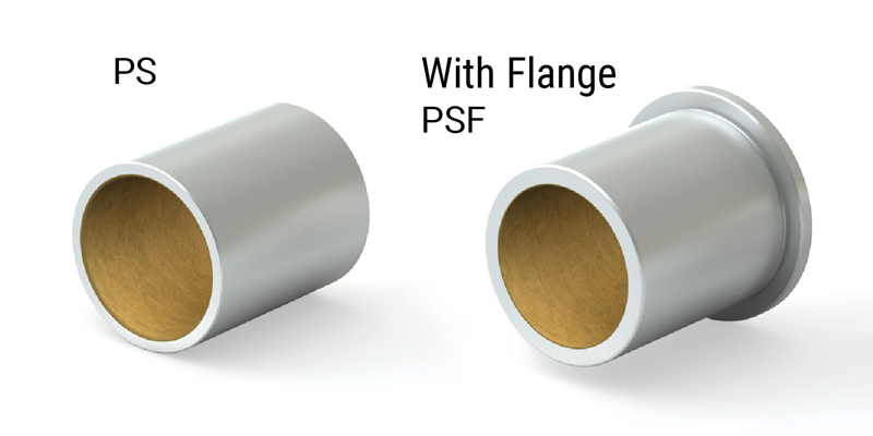
Simplicity Sleeve Bearings
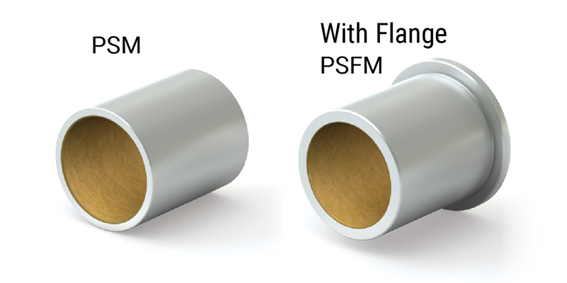
Sleeve Bearings PS
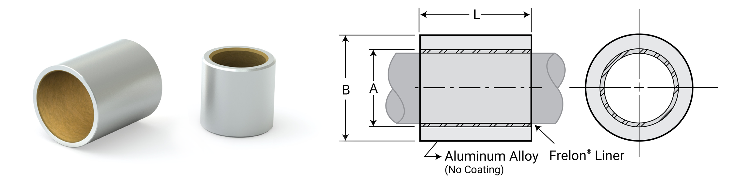
Dimensional Information
| Part No. | Nominal Bearing Size |
A Bearing I.D. |
B O.D. |
L Length |
MAX Static Load lb. FRELON® |
Bearing Weight OZ. |
Recommended Housing Bore | |||||||||
|---|---|---|---|---|---|---|---|---|---|---|---|---|---|---|---|---|
| I.D. | O.D. | Length | Min | Max | Min | Max | Min | Max | GOLD | J & W | Slip Fit & Epoxy | Press Fit | ||||
| Min | Max | Min | Max | |||||||||||||
| PS0305-02 | 3/16" | 5/16" | 1/4" | 0.1890 | 0.1900 | 0.3135 | 0.3145 | 0.230 | 0.250 | 130 | 65 | 0.02 | 0.3145 | 0.3155 | 0.3125 | 0.3130 |
| PS0305-04 | 3/16" | 5/16" | 1/2" | 0.1890 | 0.1900 | 0.3135 | 0.3145 | 0.480 | 0.500 | 272 | 136 | 0.04 | 0.3145 | 0.3155 | 0.3125 | 0.3130 |
| PS0406-02 | 1/4" | 3/8" | 1/4" | 0.2515 | 0.2525 | 0.3760 | 0.3770 | 0.230 | 0.250 | 174 | 87 | 0.03 | 0.3770 | 0.3780 | 0.3750 | 0.3755 |
| PS0406-03 | 1/4" | 3/8" | 3/8" | 0.2515 | 0.2525 | 0.3760 | 0.3770 | 0.355 | 0.375 | 268 | 134 | 0.04 | 0.3770 | 0.3780 | 0.3750 | 0.3755 |
| PS0406-04 | 1/4" | 3/8" | 1/2" | 0.2515 | 0.2525 | 0.3760 | 0.3770 | 0.480 | 0.500 | 362 | 181 | 0.05 | 0.3770 | 0.3780 | 0.3750 | 0.3755 |
| PS0610-04 | 3/8" | 5/8" | 1/2" | 0.3765 | 0.3775 | 0.6260 | 0.6270 | 0.480 | 0.500 | 542 | 271 | 0.14 | 0.6270 | 0.6280 | 0.6250 | 0.6255 |
| PS0610-06 | 3/8" | 5/8" | 3/4" | 0.3765 | 0.3775 | 0.6260 | 0.6270 | 0.730 | 0.750 | 824 | 412 | 0.20 | 0.6270 | 0.6280 | 0.6250 | 0.6255 |
| PS0710-06 | 7/16" | 5/8" | 3/4" | 0.4390 | 0.4400 | 0.6260 | 0.6270 | 0.730 | 0.750 | 962 | 481 | 0.23 | 0.6270 | 0.6280 | 0.6250 | 0.6255 |
| PS0812-04 | 1/2" | 3/4" | 1/2" | 0.5015 | 0.5025 | 0.7510 | 0.7520 | 0.480 | 0.500 | 722 | 361 | 0.15 | 0.7520 | 0.7530 | 0.7500 | 0.7505 |
| PS0812-06 | 1/2" | 3/4" | 3/4" | 0.5015 | 0.5025 | 0.7510 | 0.7520 | 0.730 | 0.750 | 1098 | 549 | 0.25 | 0.7520 | 0.7530 | 0.7500 | 0.7505 |
| PS0812-08 | 1/2" | 3/4" | 1" | 0.5015 | 0.5025 | 0.7510 | 0.7520 | 0.980 | 1.000 | 1474 | 737 | 0.35 | 0.7520 | 0.7530 | 0.7500 | 0.7505 |
| PS1014-06 | 5/8" | 7/8" | 3/4" | 0.6265 | 0.6275 | 0.8760 | 0.8770 | 0.730 | 0.750 | 1372 | 686 | 0.30 | 0.8770 | 0.8780 | 0.8750 | 0.8755 |
| PS1014-08 | 5/8" | 7/8" | 1" | 0.6265 | 0.6275 | 0.8760 | 0.8770 | 0.980 | 1.000 | 1842 | 921 | 0.45 | 0.8770 | 0.8780 | 0.8750 | 0.8755 |
| PS1216-08 | 3/4" | 1" | 1" | 0.7515 | 0.7525 | 1.0010 | 1.0020 | 0.980 | 1.000 | 2210 | 1105 | 0.50 | 1.0020 | 1.0030 | 0.9995 | 1.0000 |
| PS1216-10 | 3/4" | 1" | 1.25" | 0.7515 | 0.7525 | 1.0010 | 1.0020 | 1.230 | 1.250 | 2777 | 1389 | 0.65 | 1.0020 | 1.0030 | 0.9995 | 1.0000 |
| PS1620-12 | 1" | 1-1/4" | 1-1/2" | 1.0015 | 1.0025 | 1.2510 | 1.2520 | 1.480 | 1.500 | 4446 | 2223 | 0.95 | 1.2520 | 1.2530 | 1.2490 | 1.2500 |
| PS2024-16 | 1-1/4" | 1-1/2" | 2" | 1.2515 | 1.2525 | 1.5010 | 1.5020 | 1.980 | 2.000 | 7434 | 3717 | 1.55 | 1.5020 | 1.5030 | 1.4990 | 1.5000 |
| PS2428-16 | 1-1/2" | 1-3/4" | 2" | 1.5015 | 1.5025 | 1.7510 | 1.7520 | 1.980 | 2.000 | 8918 | 4459 | 1.80 | 1.7520 | 1.7530 | 1.7490 | 1.7500 |
| PS2832-24 | 1-3/4" | 2" | 3" | 1.7515 | 1.7525 | 2.0010 | 2.0020 | 2.980 | 3.000 | 15658 | 7829 | 3.15 | 2.0020 | 2.0030 | 1.9990 | 2.0000 |
| PS3236-24 | 2" | 2-1/4" | 3" | 2.0015 | 2.0025 | 2.2510 | 2.2520 | 2.980 | 3.000 | 17894 | 8947 | 3.55 | 2.2520 | 2.2530 | 2.2490 | 2.2500 |
| PS4044-24 | 2-1/2" | 2-3/4" | 3" | 2.5015 | 2.5025 | 2.7510 | 2.7520 | 2.980 | 3.000 | 22364 | 11182 | 4.85 | 2.7520 | 2.7530 | 2.7490 | 2.7500 |
| PS4852-28 | 3" | 3-1/4" | 3-1/2" | 3.0015 | 3.0025 | 3.2510 | 3.2520 | 3.480 | 3.500 | 31336 | 15668 | 6.10 | 3.2520 | 3.2530 | 3.2485 | 3.2495 |
Ordering Information
Note: Lengths not listed above must be specially quoted.
Additional sizes are available within our online configurator
Online Configurator
Installation Instructions
- Slip the bearing sleeve into the housing and epoxy into place with Loctite® or similar type bonding agent.
⚠ CAUTION
Do NOT let any of the adhesive touch the bearing liner. It will harden and interfere with the running clearance.
- Freeze the bearings at 0°F (-17.75°C) for 30-45 minutes. Using gloves, remove the bearings from the freezer and slip them into the housing. As they heat to room temperature, full contact between the bearing and housing will be achieved. The greatest advantage to this technique over traditional pressing is greater accuracy in alignment.
⚠ Only certified Simplicity 60 Plus Shafting provides maximum linear bearing performance.
Simplicity Sleeve Bearings
with Flange
Sleeve Bearings with Flange PSF
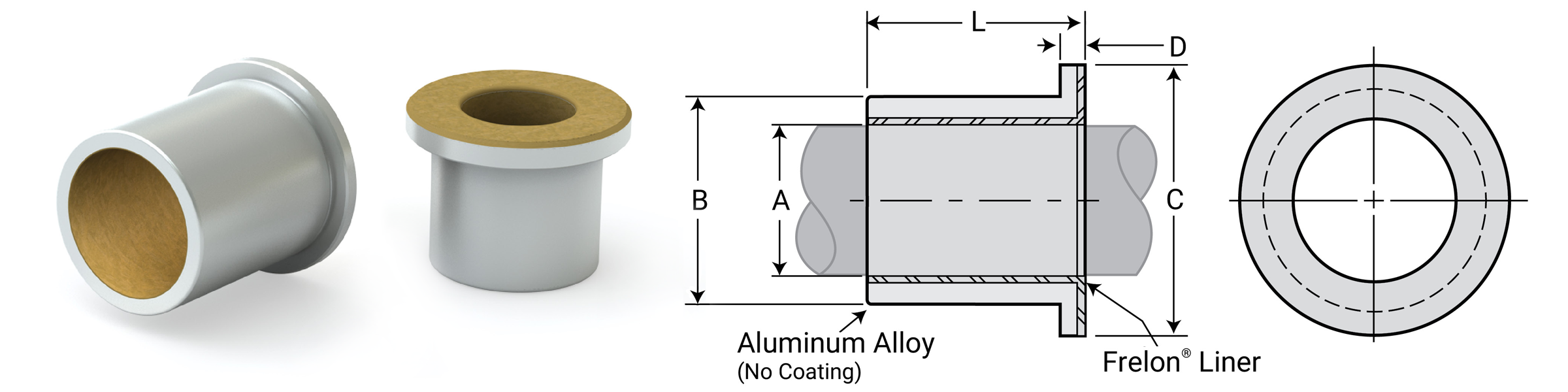
Dimensional Information
| Part No. | Nominal Bearing Size | A Bearing I.D. |
B O.D. |
C Flange O.D. |
D Flange Width |
L Length |
MAX Static Load lb. FRELON® |
Bearing Weight OZ. |
Recommended Housing Bore | |||||||||
|---|---|---|---|---|---|---|---|---|---|---|---|---|---|---|---|---|---|---|
| I.D. | O.D. | Length | Min | Max | Min | Max | Min | Max | GOLD | J & W | Slip Fit & Epoxy | Press Fit | ||||||
| Min | Max | Min | Max | |||||||||||||||
| PSF0305-02 | 3/16" | 5/16" | 1/4" | 0.1890 | 0.1900 | 0.3135 | 0.3145 | 0.4370 | 0.0625 | 0.230 | 0.250 | 130 | 65 | 0.023 | 0.3145 | 0.3155 | 0.3125 | 0.3130 |
| PSF0305-04 | 3/16" | 5/16" | 1/2" | 0.1890 | 0.1900 | 0.3135 | 0.3145 | 0.4370 | 0.0625 | 0.480 | 0.500 | 272 | 136 | 0.044 | 0.3145 | 0.3155 | 0.3125 | 0.3130 |
| PSF0406-02 | 1/4" | 3/8" | 1/4" | 0.2515 | 0.2525 | 0.3760 | 0.3770 | 0.5000 | 0.0625 | 0.230 | 0.250 | 174 | 87 | 0.031 | 0.3770 | 0.3780 | 0.3750 | 0.3755 |
| PSF0406-03 | 1/4" | 3/8" | 3/8" | 0.2515 | 0.2525 | 0.3760 | 0.3770 | 0.5000 | 0.0625 | 0.355 | 0.375 | 268 | 134 | 0.044 | 0.3770 | 0.3780 | 0.3750 | 0.3755 |
| PSF0406-04 | 1/4" | 3/8" | 1/2" | 0.2515 | 0.2525 | 0.3760 | 0.3770 | 0.5000 | 0.0625 | 0.480 | 0.500 | 362 | 181 | 0.055 | 0.3770 | 0.3780 | 0.3750 | 0.3755 |
| PSF0610-04 | 3/8" | 5/8" | 1/2" | 0.3765 | 0.3775 | 0.6260 | 0.6270 | 0.8750 | 0.1250 | 0.480 | 0.500 | 542 | 271 | 0.20 | 0.6270 | 0.6280 | 0.6250 | 0.6255 |
| PSF0610-06 | 3/8" | 5/8" | 3/4" | 0.3765 | 0.3775 | 0.6260 | 0.6270 | 0.8750 | 0.1250 | 0.730 | 0.750 | 824 | 412 | 0.25 | 0.6270 | 0.6280 | 0.6250 | 0.6255 |
| PSF0710-06 | 7/16" | 5/8" | 3/4" | 0.4390 | 0.4400 | 0.6260 | 0.6270 | 0.9375 | 0.1250 | 0.730 | 0.750 | 962 | 481 | 0.20 | 0.6270 | 0.6280 | 0.6250 | 0.6255 |
| PSF0812-04 | 1/2" | 3/4" | 1/2" | 0.5015 | 0.5025 | 0.7510 | 0.7520 | 1.0000 | 0.1250 | 0.480 | 0.500 | 722 | 361 | 0.25 | 0.7520 | 0.7530 | 0.7500 | 0.7505 |
| PSF0812-06 | 1/2" | 3/4" | 3/4" | 0.5015 | 0.5025 | 0.7510 | 0.7520 | 1.0000 | 0.1250 | 0.730 | 0.750 | 1098 | 549 | 0.30 | 0.7520 | 0.7530 | 0.7500 | 0.7505 |
| PSF0812-08 | 1/2" | 3/4" | 1" | 0.5015 | 0.5025 | 0.7510 | 0.7520 | 1.0000 | 0.1250 | 0.980 | 1.000 | 1474 | 737 | 0.40 | 0.7520 | 0.7530 | 0.7500 | 0.7505 |
| PSF1014-06 | 5/8" | 7/8" | 3/4" | 0.6265 | 0.6275 | 0.8760 | 0.8770 | 1.0000 | 0.1250 | 0.730 | 0.750 | 1372 | 686 | 0.35 | 0.8770 | 0.8780 | 0.8750 | 0.8755 |
| PSF1014-08 | 5/8" | 7/8" | 1" | 0.6265 | 0.6275 | 0.8760 | 0.8770 | 1.0000 | 0.1250 | 0.980 | 1.000 | 1842 | 921 | 0.45 | 0.8770 | 0.8780 | 0.8750 | 0.8755 |
| PSF1216-08 | 3/4" | 1" | 1" | 0.7515 | 0.7525 | 1.0010 | 1.0020 | 1.2500 | 0.1250 | 0.980 | 1.000 | 2210 | 1105 | 0.55 | 1.0020 | 1.0030 | 0.9995 | 1.0000 |
| PSF1620-12 | 1" | 1-1/4" | 1-1/2" | 1.0015 | 1.0025 | 1.2510 | 1.2520 | 1.5000 | 0.1250 | 1.480 | 1.500 | 4446 | 2223 | 1.05 | 1.2520 | 1.2530 | 1.2490 | 1.2500 |
| PSF2024-16 | 1-1/4" | 1-1/2" | 2" | 1.2515 | 1.2525 | 1.5010 | 1.5020 | 1.7500 | 0.1250 | 1.980 | 2.000 | 7434 | 3717 | 1.80 | 1.5020 | 1.5030 | 1.4990 | 1.5000 |
| PSF2428-16 | 1-1/2" | 1-3/4" | 2" | 1.5015 | 1.5025 | 1.7510 | 1.7520 | 2.0000 | 0.1250 | 1.980 | 2.000 | 8918 | 4459 | 2.16 | 1.7520 | 1.7530 | 1.7490 | 1.7500 |
| PSF2832-24 | 1-3/4" | 2" | 3" | 1.7515 | 1.7525 | 2.0010 | 2.0020 | 2.2500 | 0.1250 | 2.980 | 3.000 | 15658 | 7829 | 3.30 | 2.0020 | 2.0030 | 1.9990 | 2.0000 |
| PSF3236-24 | 2" | 2-1/4" | 3" | 2.0015 | 2.0025 | 2.2510 | 2.2520 | 2.5000 | 0.1250 | 2.980 | 3.000 | 17894 | 8947 | 3.75 | 2.2520 | 2.2530 | 2.2490 | 2.2500 |
| PSF4044-24 | 2-1/2" | 2-3/4" | 3" | 2.5015 | 2.5025 | 2.7510 | 2.7520 | 3.0000 | 0.1250 | 2.980 | 3.000 | 22364 | 11182 | 4.60 | 2.7520 | 2.7530 | 2.7490 | 2.7500 |
| PSF4852-28 | 3" | 3-1/4" | 3-1/2" | 3.0015 | 3.0025 | 3.2510 | 3.2520 | 3.5000 | 0.1250 | 3.480 | 3.500 | 31336 | 15668 | 6.30 | 3.2520 | 3.2530 | 3.2485 | 3.2495 |
Ordering Information
Note: Lengths not listed above must be specially quoted.
Additional sizes are available within our online configurator
Online Configurator
Installation Instructions
- Slip the bearing sleeve into the housing and epoxy into place with Loctite® or similar type bonding agent.
⚠ CAUTION
Do NOT let any of the adhesive touch the bearing liner. It will harden and interfere with the running clearance.
- Freeze the bearings at 0°F (-17.75°C) for 30-45 minutes. Using gloves, remove the bearings from the freezer and slip them into the housing. As they heat to room temperature, full contact between the bearing and housing will be achieved. The greatest advantage to this technique over traditional pressing is greater accuracy in alignment.
⚠ Only certified Simplicity 60 Plus Shafting provides maximum linear bearing performance.
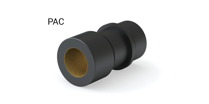
Simplicity Die Set Bushings
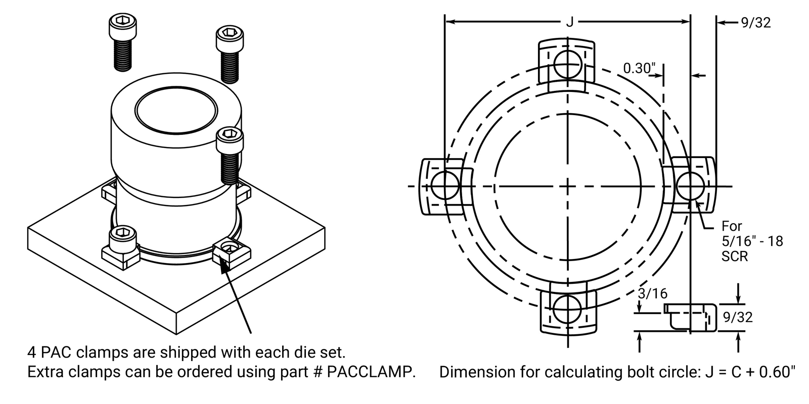
Die Set Bushings PAC
Dimensional Information
| P = Precision C = Compensated |
Part No. | Nominal Size in. |
A Bearing I.D. |
B B Flange & Barrel O.D. |
C Clamp Dia. Min |
D Pilot O.D. |
E Pilot Length |
F Flange Length |
G Recess Length |
H Head Length |
I Overall Length |
Effective Surface Area sq. in. |
MAX Static Load lb. FRELON® |
Bearing Weight lb. |
||||
|---|---|---|---|---|---|---|---|---|---|---|---|---|---|---|---|---|---|---|
| Min | Max | Min | Max | Min | Max | GOLD | J & W | |||||||||||
|
P C |
PACZ750 PACZ750C |
3/4 | 0.750 0.753 |
0.7510 0.7540 |
1.285 | 1.300 | 1.012 | 1.1245 | 1.1250 | 0.812 | 0.188 | 0.712 | 2.000 | 2.812 | 2.209 | 6626 | 3313 | 0.625 |
|
P C |
PACZ100 PACZ100C |
1 | 1.000 1.003 |
1.0010 1.0040 |
1.723 | 1.738 | 1.450 | 1.4995 | 1.5000 | 0.875 | 0.188 | 0.812 | 2.250 | 3.125 | 3.272 | 9817 | 4909 | 1.000 |
|
P C |
PACZ125 PACZ125C |
1-1/4 | 1.250 1.254 |
1.2510 1.2550 |
2.097 | 2.112 | 1.825 | 1.7495 | 1.7500 | 1.125 | 0.188 | 0.812 | 2.375 | 3.500 | 4.581 | 13744 | 6872 | 1.500 |
|
P C |
PACZ150 PACZ150C |
1-1/2 | 1.500 1.504 |
1.5012 1.5050 |
2.346 | 2.361 | 2.075 | 1.9995 | 2.0000 | 1.375 | 0.188 | 1.112 | 2.750 | 4.125 | 6.480 | 19439 | 9719 | 2.000 |
|
P C |
PACZ200 PACZ200C |
2 | 2.000 2.005 |
2.0014 2.0064 |
3.095 | 3.110 | 2.825 | 2.4995 | 2.5000 | 1.625 | 0.188 | 1.112 | 3.000 | 4.625 | 9.687 | 29060 | 14530 | 4.188 |
|
P C |
PACZ250 PACZ250C |
2-1/2 | 2.500 2.505 |
2.5016 2.5065 |
3.595 | 3.610 | 3.325 | 2.9995 | 3.0000 | 1.875 | 0.188 | 1.112 | 3.500 | 5.375 | 14.072 | 42215 | 21108 | 6.000 |
|
P C |
PACZ300 PACZ300C |
3 | 3.000 3.006 |
3.0020 3.0080 |
4.345 | 4.360 | 4.075 | 3.6245 | 3.6250 | 1.875 | 0.188 | 1.112 | 4.000 | 5.875 | 18.457 | 55371 | 27685 | 10.000 |
Notes:
(1) Formula used for effective surface area is (pi * ID * L)/3.
(2) Shell material is aluminum.
(3) For lubrication system add JKM, example: PACZ750JKM.
(4) Max static load is effective surface area times max load for FrelonGOLD®.
(5) – 3000 psi is the rating for FrelonGOLD®: 1500 psi is the rating for Frelon J & W.
Plain Bearings Accessories
1. Retaining Rings (External)
| FL Series | Part No. |
|---|---|
| FL03 | 6010001 |
| FL04 | 6010002 |
| FL06 | 6010003 |
| FL08 | 6010004 |
| FL10 | 6010005 |
| FL12 | 6010006 |
| FL16 | 6010007 |
| FL20 | 6010008 |
| FL24 | 6010009 |
| FL32 | 6010010 |
| FL40 | 6010011 |
| FL48 | 6010012 |
| FL64 | 6010013 |
| FM Series | Part No. |
|---|---|
| FM05 | 6010014 |
| FM08 | 6010015 |
| FM10 | 6010016 |
| FM12 | 6010017 |
| FM16 | 6010018 |
| FM20 | 6010019 |
| FM25 | 6010020 |
| FM30 | 6010021 |
| FM40 | 6010022 |
| FM50 | 6010023 |
| FM60 | 6010024 |
| FM80 | 6010025 |
2. Seals
| FL Series | Part No. | ||
|---|---|---|---|
| Polymod | Viton | Urethane | |
| FL08 | 6030001 | 6030009 | 6030017 |
| FL10 | 6030002 | 6030010 | 6030018 |
| FL12 | 6030003 | 6030011 | 6030019 |
| FL16 | 6030004 | 6030012 | 6030020 |
| FL20 | 6030005 | 6030013 | 6030021 |
| FL24 | 6030006 | 6030014 | 6030022 |
| FL32 | 6030007 | 6030015 | 6030023 |
| FL40 | 6030008 | 6030016 | 6030024 |
| FL48 | N/A | N/A | 6030025 |
| FL64 | N/A | N/A | 6030026 |
| FM/FJ Series | Part No. | ||
|---|---|---|---|
| FM20/FJ20 | N/A | N/A | 6030027 |
| FM25/FJ25 | N/A | N/A | 6030028 |
| FM30/FJ30 | N/A | N/A | 6030029 |
| FJ35 | N/A | N/A | 6030030 |
| FJ38 | N/A | N/A | 6030030 |
| FM40/FJ40 | N/A | N/A | 6030031 |
| FM50/FJ50 | N/A | N/A | 6030032 |
| FM60/FJ60 | N/A | N/A | 6030033 |
| FM80/FJ80 | N/A | N/A | 6030034 |
| FJ100 | N/A | N/A | 6030052 |
| FJ120 | N/A | N/A | 6030053 |
3. O-Rings
| FL Series | Part No. | |
|---|---|---|
| Nitrile buna 70 | Viton | |
| FL04 | 6000001 | N/A |
| FL06 | 6000002 | 6000037 |
| FL08 | 6000003 | 6000038 |
| FL10 | 6000004 | 6000039 |
| FL12 | 6000005 | 6000040 |
| FL16 | 6000006 | 6000041 |
| FL20 | 6000007 | 6000042 |
| FL24 | 6000008 | 6000043 |
| FL32 | 6000009 | 6000044 |
| FL40 | 6000010 | 6000045 |
| FL48 | 6000011 | 6000046 |
| FL64 | 6000012 | 6000047 |
| FM/FJ Series | Part No. | |
|---|---|---|
| FM08 | 6000014 | N/A |
| FM10 | 6000015 | N/A |
| FM12 | 6000016 | N/A |
| FM16 | 6000017 | N/A |
| FM20 | 6000018 | N/A |
| FM25 | 6000019 | N/A |
| FM30 | 6000020 | N/A |
| FM40 | 6000021 | N/A |
| FM50 | 6000022 | N/A |
| FM60 | 6000023 | N/A |
| FM80 | 6000024 | N/A |
4. Zerk Fittings
| Inch | Part No. | |
|---|---|---|
| 1/4-28" | Steel | 6050002 |
| 1/4-28" | Stainless | 6050003 |
| Metric | Part No. |
|---|---|
| M8 x 1.0 Steel | 6050001 |
5. Retaining Rings (Internal)
| *Inch Open | Part No. | *Metric Open | Part No. | |||
|---|---|---|---|---|---|---|
| Steel | Stainless Steel | Steel | Stainless Steel | |||
| PN08 | 6010035 | 6010064 | PMN12 | 6010044 | N/A | |
| PN10 | 6010036 | 6010066 | PMN16 | 6010045 | 6010107 | |
| PN12 | 6010037 | 6010068 | PMN20 | 6010046 | N/A | |
| PN16 | 6010038 | 6010070 | PMN25 | 6010047 | N/A | |
| PN20 | 6010039 | 6010072 | PMN30 | 6010048 | 6010083 | |
| PN24 | 6010040 | 6010074 | PMN40 | 6010049 | N/A | |
| PN32 | 6010041 | 6010076 | PMN50 | 6010050 | N/A | |
| Closed | Part No. | Closed | Part No. | ||
|---|---|---|---|---|---|
| P04 | 6010026 | 6010052 | PM08 | 6010042 | N/A |
| P06 | 6010027 | 6010053 | PM10 | 6010043 | N/A |
| P08 | 6010028 | 6010054 | PM12 | 6010044 | N/A |
| P10 | 6010029 | 6010055 | PM16 | 6010045 | 6010107 |
| P12 | 6010030 | 6010056 | PM20 | 6010046 | N/A |
| P16 | 6010031 | 6010057 | PM25 | 6010047 | N/A |
| P20 | 6010032 | 6010058 | PM30 | 6010048 | 6010083 |
| P24 | 6010033 | 6010059 | PM40 | 6010049 | N/A |
| P32 | 6010034 | 6010060 | PM50 | 6010050 | N/A |
6. Roll Pin
| Inch | Part No. | |
|---|---|---|
| PN08 | 6060001 | |
| PN10 | 6060002 | |
| PN12 | 6060003 | |
| PN16 | 6060004 | |
| PN20 | 6060005 | |
| PN24 | 6060006 | |
| PN32 | 6060007 | |
| Metric Open | Part No. |
|---|---|
| PMN12 | 6060010 |
| PMN16 | 6060009 |
| PMN20 | 6060009 |
| PMN25 | 6060010 |
| PMN30 | 6060010 |
| PMN40 | 6060012 |
| PMN50 | 6060012 |
* Purchased retaining ring components (an accessory item listed above) are the custom's responsibility to trim/cut tabbed ends. When purchased as part of a PBC Linear complete pre-assembled open pillow block assembly, tabbed ends will be trimmed/cut at factory prior to shipment.
Ball Bearings Overview
Product Overview
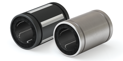
High Precision and Regidity
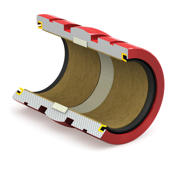
The Simplicity® ball bearing is produced from a solid steel outer cylinder and incorporates an industrial strength polymer retainer.
Ease of Assembly
The standard type of linear ball bearing can be loaded from any direction. Precision control is possible using only the shaft supporter, and the mounting surface can be machined easily.
Ease of Replacement
Linear ball bearings of each type are completely interchangeable because of their standardized dimensions and strict precision control. Replacement because of wear or damage is therefore easy and accurate.
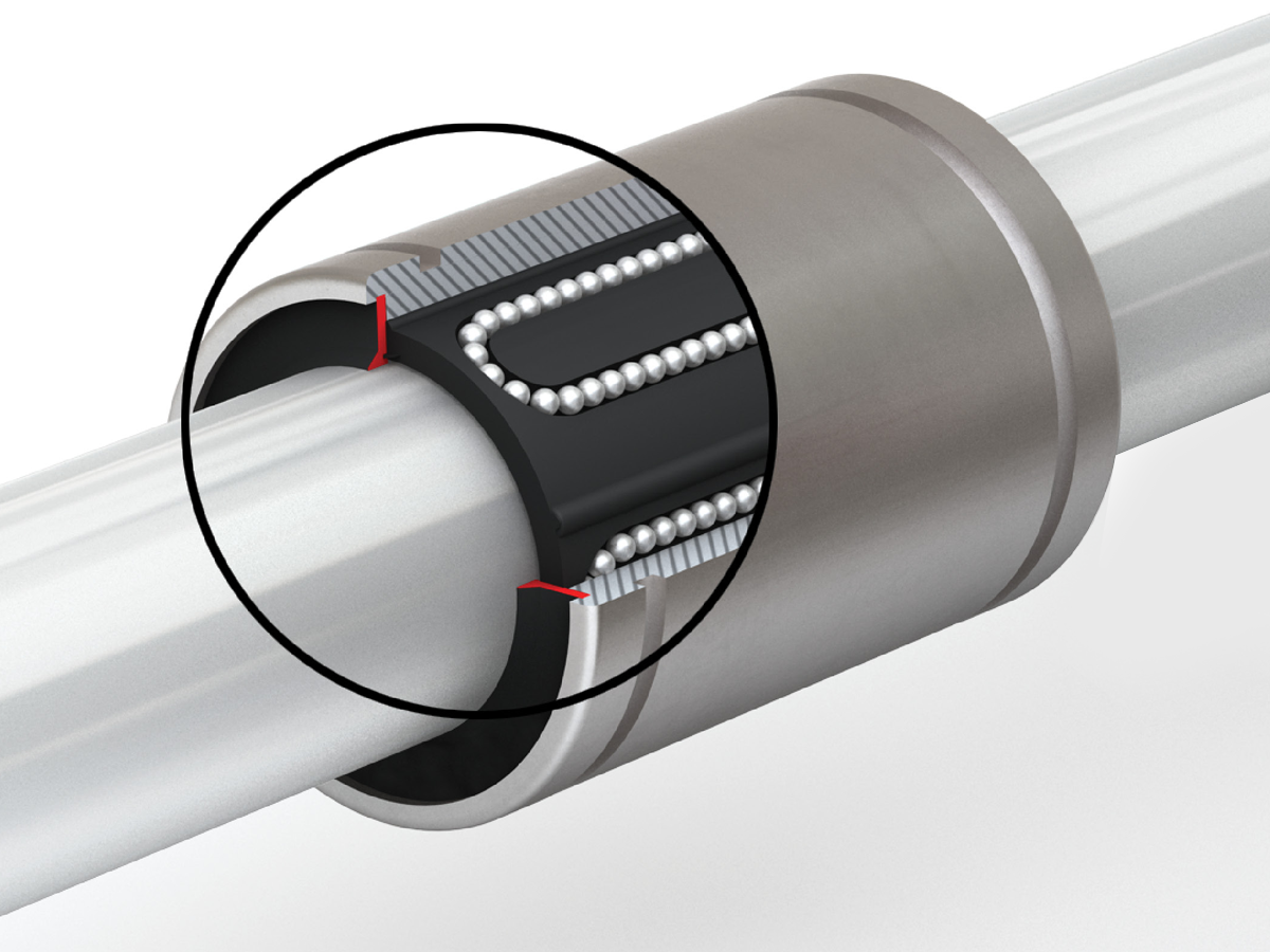
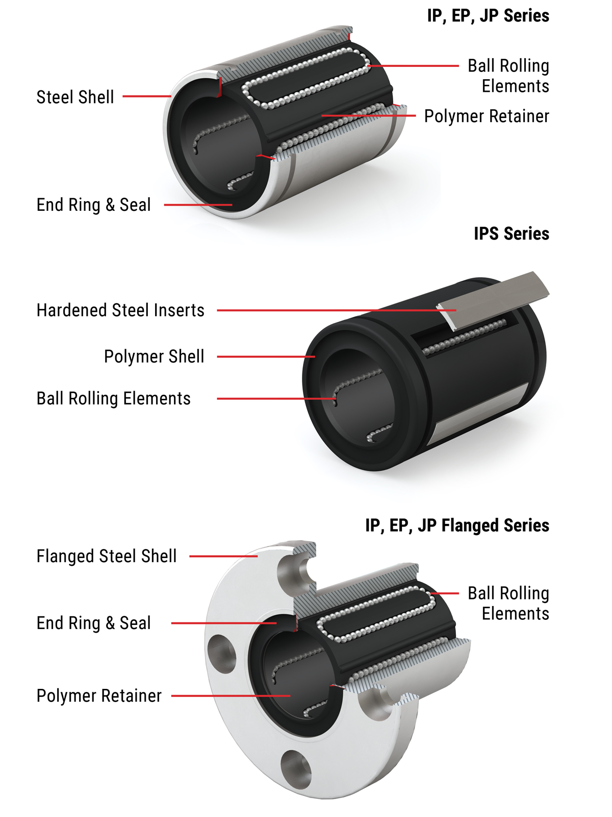
Materials
Ball bearings consist of an outer cylinder, ball retainer, balls, double seals, and two end rings. The ball retainer which holds the balls in the recirculating tracks is held inside the outer cylinder by end rings.
- Parts are assembled to optimize their required functions
- The outer shell is heat treated to ensure long life
- The ball retainer is molded from a durable polymer to ensure smooth and quiet motion
- Double seals are standard
Variety of Types
PBC Linear offers a full line of ball bearings that include:
- Inch, ISO Metric, and JIS Metric sizes
- Self-aligning super ball bearings in Inch sizes
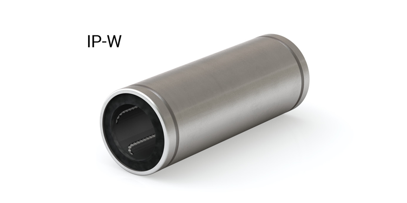
- Double wide in Inch, ISO Metric, and JIS Metric sizes
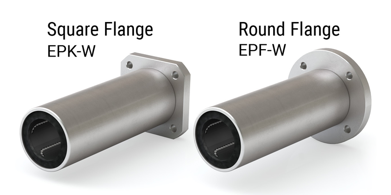
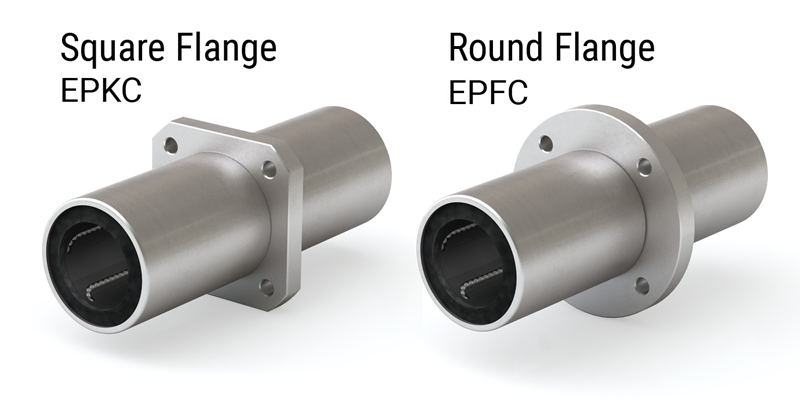
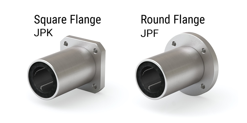
- Square and round flange in ISO Metric and JIS Metric sizes
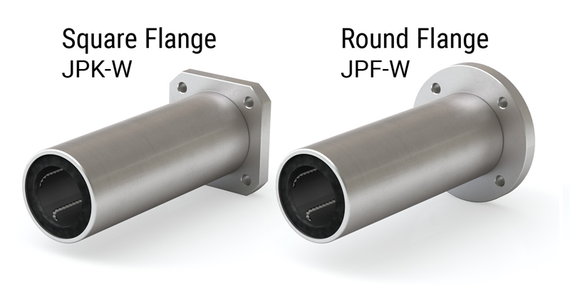
- Double wide square and round flange in ISO Metric and JIS Metric sizes
- Double wide with center flange location in ISO Metric and JIS Metric sizes
- Pillow blocks, open and closed, in Inch and ISO Metric
- Double wide pillow blocks in Inch sizes
⚠ Only certified Simplicity 60 Plus Shafting provides maximum linear bearing performance.
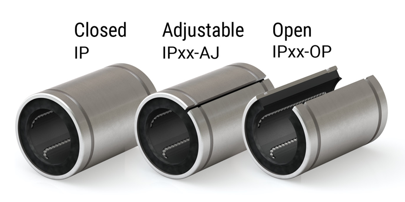
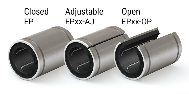
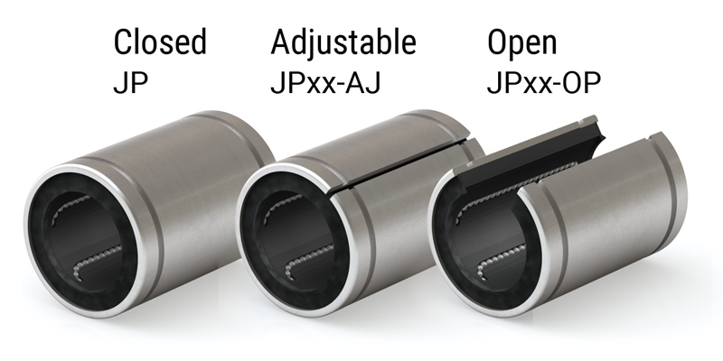
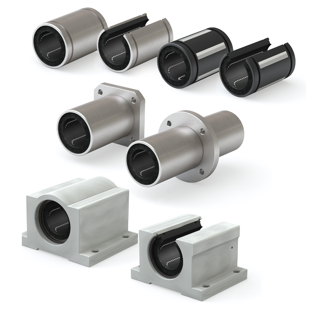
Simplicity® linear ball bearings are available in a variety of configurations designed to meet a range of application needs.
Bearings – IP, EP, and JP Series (Inch, ISO, and JIS Metric)
- Solid steel outer shell
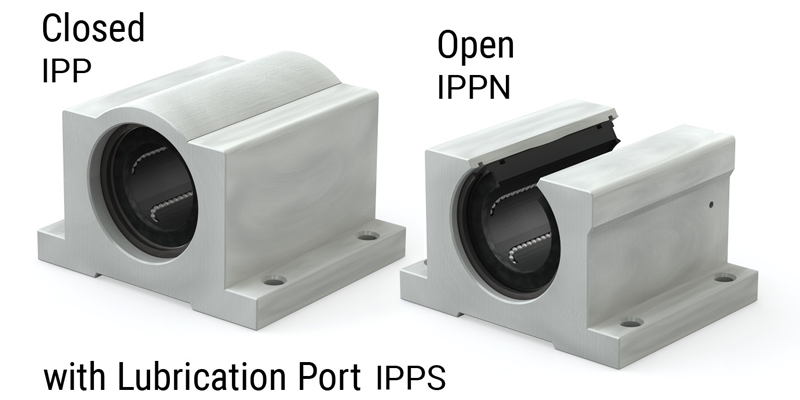
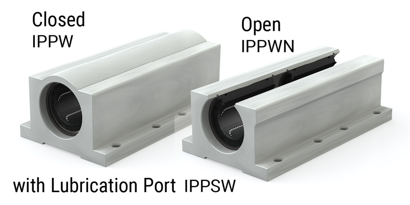
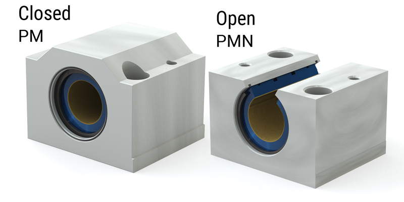
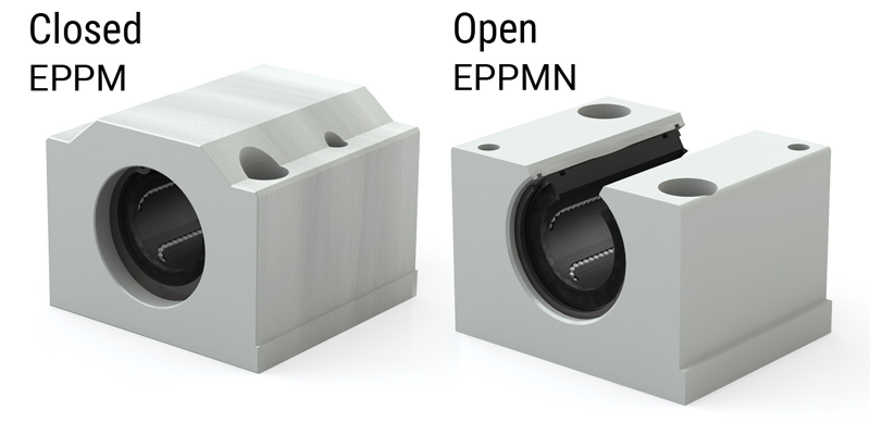
Pillow Blocks – IPP and EPP (Inch and ISO Metric)
- Aluminum housing with bearing insert
- Industrial strength polymer ball retainer
- End rings with integrated seals standard
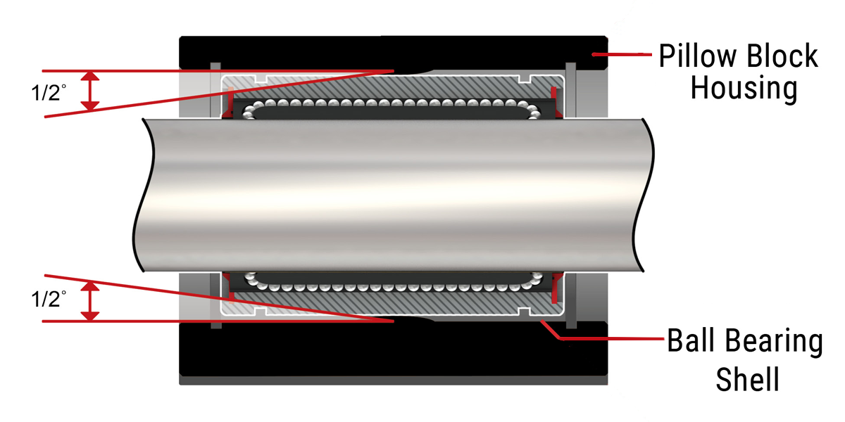
- Used in standard PBC Linear pillow blocks that supply 1/2° self-alignment in all directions
- Excellent rigidity while providing smooth, quiet operation
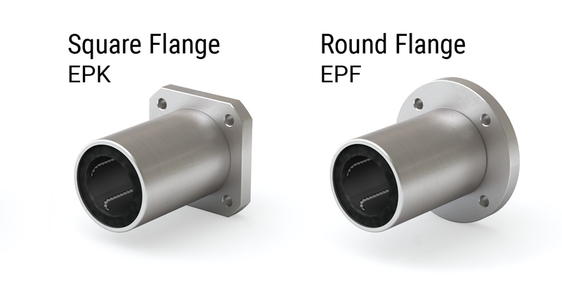
Flanged Bearings – EP, and JP Series (ISO, and JIS Metric)
- Solid steel outer shell
- Industrial strength polymer ball retainer
- End rings with integrated seals standard
- Excellent rigidity while providing smooth, quiet operation
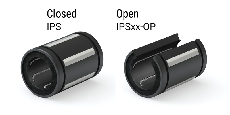
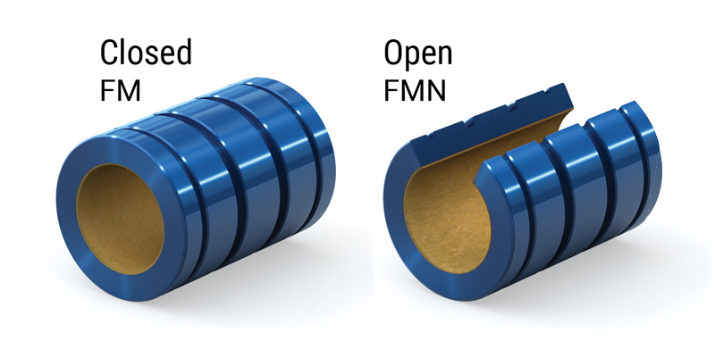
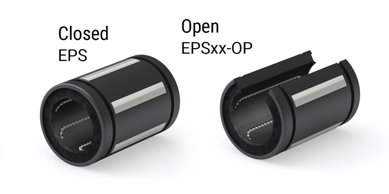
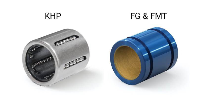
IPS and EPS Series
- Outer shell is of high strength polymer
- Ball bearing raceway inserts are hardened steel
- Inserts allow smooth ball rotation while maintaining even preload with the shaft or inner race
- Inserts provide 1/2° self-alignment in all directions when used in a straight bore pillow block or housing
- Provide increased load capacity and life in a lightweight design
Self-Aligning Pillow Blocks
Pillow blocks combine linear ball bearings with PBC Linear’s self aligning pillow block to compensate for misalignment or shaft deflection in the application
- Straight OD bearings are used in standard PBC Linear pillow blocks that supply 1/2° self-alignment in all directions
- Straight bore pillow blocks are also available for applications which demand more rigidity
- PBC Linear’s bearings are size interchangeable with industry standard ball bearings and with Simplicity plain bearings
Ordering Information
Ball Bearings
| Series | Flange Type | Center Flange Location | Nominal Shaft Diameter | Retainer Material | Width | Modification | |
| IP | 10 | G | - | AJ | |||
Series
Flange Type
Flange available only on EP, and JP series Center Flange Location
Flange available only on EP, and JP series Nominal Shaft DiameterEnglish units in 16ths of an inch Metric units in mm Retainer Material
G available only on IP, EP, and JP series Width
Available only on IP, EP, and JP series Modification
IPS available only closed or open KHP available only closed |
Note: Precision of inscribed circle diameters and outside diameters for the clearance adjustable type (…-AJ) and the open type (…-OP) indicates the value obtained before the corresponding type is subjected to cutting process.
Ball Bearing Pillow Blocks
| Pillow Block Type | Housing/Bearing Type | Nominal Shaft Diameter | Retainer Material |
| IPP | 12 | G | |
Pillow Block Type
Housing/Bearing Type
Nominal Shaft DiameterEnglish units in 16ths of an inch Metric units in mm Retainer Material
|
Linear Ball Bearings
Linear Ball Bearings Precision
Ball Bearings IP
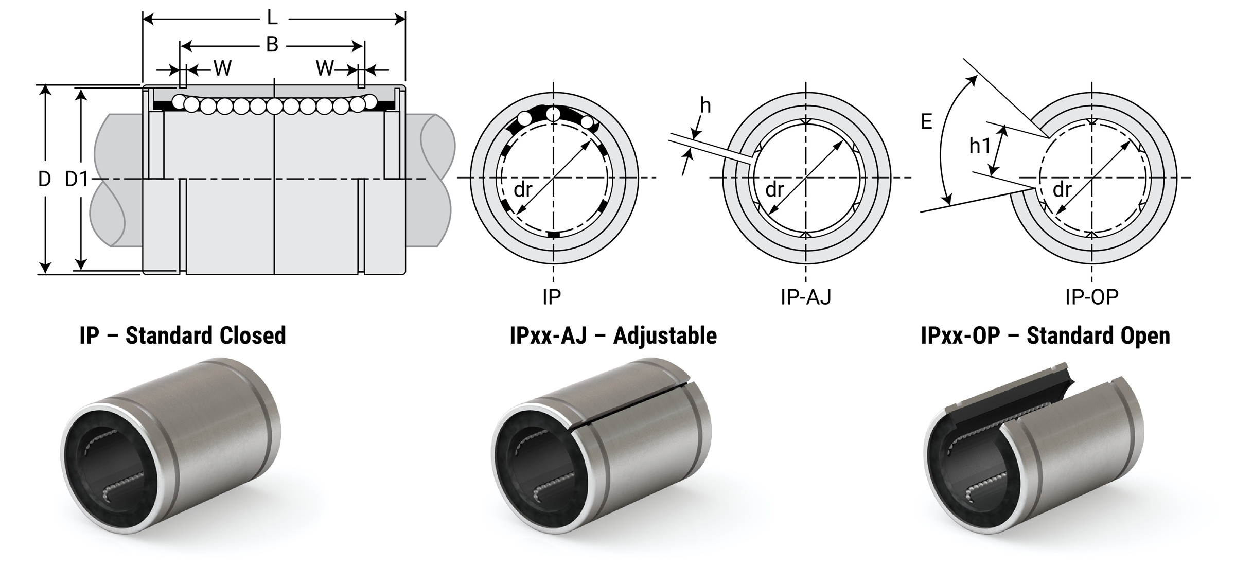
Dimensional Information
| Part No. | Nominal Diameter | Ball Circuit | Weight G |
Major Dimensions & Tolerances | |||||||||
|---|---|---|---|---|---|---|---|---|---|---|---|---|---|
| Standard Closed | Adjustable | Standard Open | Size In. |
Dr In. |
Tolerance In. |
D In. |
Tolerance In. |
L In. |
Tolerance In. |
B In. |
Tolerance In. |
||
| IP4G | - | - | 1/4 | 0.2500 | 0/-0.0005 | 4 | 8 | 0.5000 | 0/-.00045 | 0.7500 | 0/-0.008 | 0.5110 | 0/-0.008 |
| IP6G | - | - | 3/8 | 0.3750 | 0/-0.0005 | 4 | 15 | 0.6250 | 0/-.00050 | 0.8750 | 0/-0.008 | 0.6358 | 0/-0.008 |
| IP8G | IP8G-AJ | IP8G-OP | 1/2 | 0.5000 | 0/-0.0005 | 4 | 42 | 0.8750 | 0/-.00050 | 1.2500 | 0/-0.008 | 0.9625 | 0/-0.008 |
| IP10G | IP10G-AJ | IP10G-OP | 5/8 | 0.6250 | 0/-0.0005 | 5 | 85 | 1.1250 | 0/-.00050 | 1.5000 | 0/-0.008 | 1.1039 | 0/-0.008 |
| IP12G | IP12G-AJ | IP12G-OP | 3/4 | 0.7500 | 0/-0.0005 | 5 | 104 | 1.2500 | 0/-.00065 | 1.6250 | 0/-0.008 | 1.1657 | 0/-0.008 |
| IP16G | IP16G-AJ | IP16G-OP | 1 | 1.0000 | 0/-0.0005 | 6 | 220 | 1.5625 | 0/-.00065 | 2.2500 | 0/-0.012 | 1.7547 | 0/-0.012 |
| IP20G | IP20G-AJ | IP20G-OP | 1-1/4 | 1.2500 | 0/-0.0006 | 6 | 465 | 2.0000 | 0/-.00075 | 2.6250 | 0/-0.012 | 2.0047 | 0/-0.012 |
| IP24G | IP24G-AJ | IP24G-OP | 1-1/2 | 1.5000 | 0/-0.0006 | 6 | 720 | 2.3750 | 0/-.00075 | 3.0000 | 0/-0.012 | 2.4118 | 0/-0.012 |
| IP32G | IP32G-AJ | IP32G-OP | 2 | 2.0000 | 0/-0.0008 | 6 | 1310 | 3.0000 | 0/-.00090 | 4.0000 | 0/-0.012 | 3.1917 | 0/-0.012 |
| Part No. | Nominal Diameter | Major Dimensions & Tolerances | Load Ratings | |||||||||||
|---|---|---|---|---|---|---|---|---|---|---|---|---|---|---|
| Standard Closed | Adjustable | Standard Open | Size In. |
dr In. |
Tolerance In. |
W In. |
D1 In. |
H In. |
h1 In. |
E Slot Angle |
Max Eccentricity In. |
Max Radial Clearance In. |
Dynamic C lb. |
Static Co lb. |
| IP4G | - | - | 1/4 | 0.2500 | 0/-0.0005 | 0.0390 | 0.4687 | - | - | - | 0.0004 | -0.0001 | 46 | 59 |
| IP6G | - | - | 3/8 | 0.3750 | 0/-0.0005 | 0.0390 | 0.5880 | - | - | - | 0.0004 | -0.0001 | 50 | 70 |
| IP8G | IP8G-AJ | IP8G-OP | 1/2 | 0.5000 | 0/-0.0005 | 0.0459 | 0.8209 | 0.06 | 0.3400 | 80° | 0.0004 | -0.0001 | 114 | 176 |
| IP10G | IP10G-AJ | IP10G-OP | 5/8 | 0.6250 | 0/-0.0005 | 0.0559 | 1.0590 | 0.06 | 0.3750 | 80° | 0.0004 | -0.0001 | 174 | 265 |
| IP12G | IP12G-AJ | IP12G-OP | 3/4 | 0.7500 | 0/-0.0005 | 0.0559 | 1.1760 | 0.06 | 0.4375 | 60° | 0.0005 | -0.0002 | 193 | 307 |
| IP16G | IP16G-AJ | IP16G-OP | 1 | 1.0000 | 0/-0.0005 | 0.0679 | 1.4687 | 0.06 | 0.5625 | 50° | 0.0005 | -0.0002 | 220 | 352 |
| IP20G | IP20G-AJ | IP20G-OP | 1-1/4 | 1.2500 | 0/-0.0006 | 0.0679 | 1.8859 | 0.10 | 0.6250 | 50° | 0.0007 | -0.0003 | 352 | 615 |
| IP24G | IP24G-AJ | IP24G-OP | 1-1/2 | 1.5000 | 0/-0.0006 | 0.0859 | 2.2389 | 0.12 | 0.7500 | 50° | 0.0007 | -0.0003 | 490 | 903 |
| IP32G | IP32G-AJ | IP32G-OP | 2 | 2.0000 | 0/-0.0008 | 0.1029 | 2.8379 | 0.12 | 1.000 | 50° | 0.0009 | -0.0005 | 858 | 1784 |
⚠ Only certified Simplicity 60 Plus Shafting provides maximum linear bearing performance.
Linear Ball Bearings Precision Plus Self Aligning
Precision Plus Self Aligning Ball Bearings IPS & IPSXX-OP
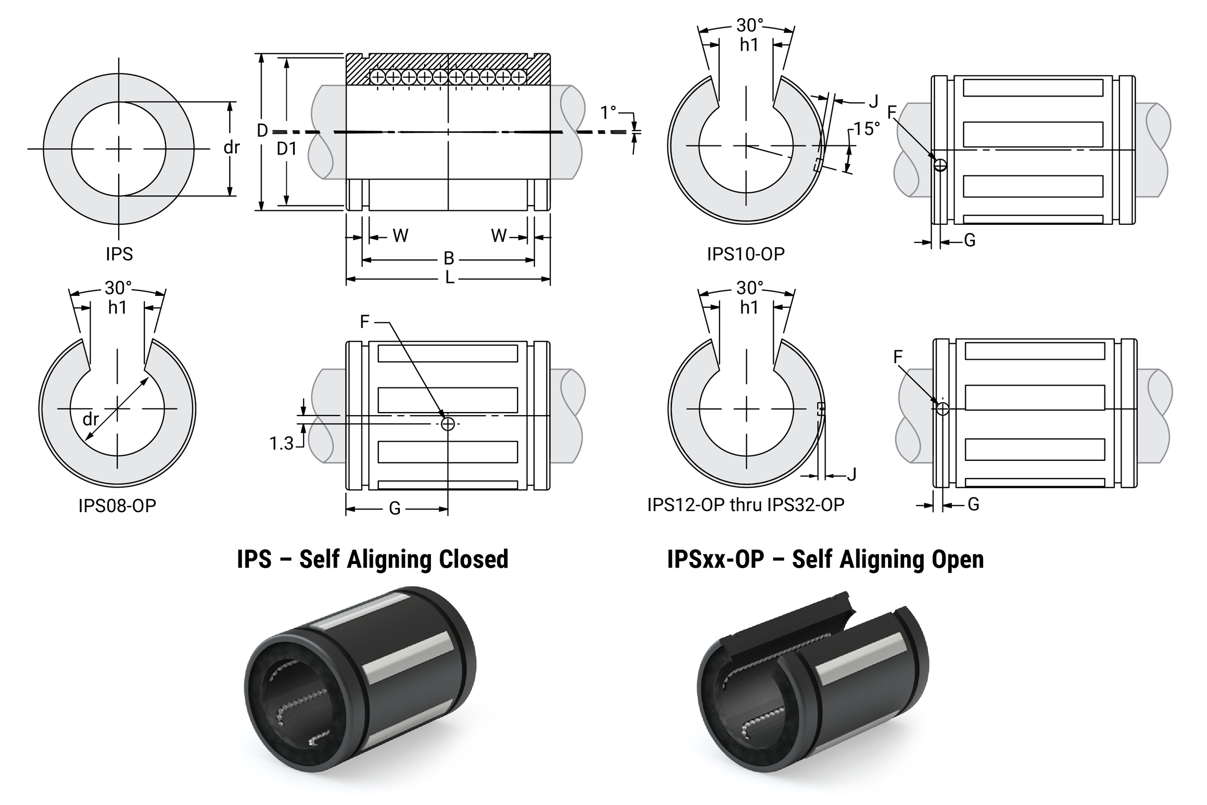
Dimensional Information
| Part No. Self Aligning Closed |
Nominal Diameter | Ball Circuit | Weight lb. |
Major Dimensions & Tolerances | Load Ratings | |||||||||
|---|---|---|---|---|---|---|---|---|---|---|---|---|---|---|
| Size In. |
dr In. |
Tolerance In. |
D In. |
L In. |
Tolerance In. |
B In. |
Tolerance In. |
W In. |
D1 In. |
Dynamic C lb. |
Static Co lb. |
|||
| IPS04 | 1/4 | 0.2500 | 0/-0.0005 | 4 | 0.009 | 0.5000 | 0.7500 | 0/-0.015 | 0.515 | 0/-0.015 | 0.0390 | 0.4687 | 57 | 49 |
| IPS06 | 3/8 | 0.3750 | 0/-0.0005 | 4 | 0.014 | 0.6250 | 0.8750 | 0/-0.015 | 0.703 | 0/-0.015 | 0.0390 | 0.5880 | 78 | 66 |
| IPS08 | 1/2 | 0.5000 | 0/-0.0005 | 4 | 0.043 | 0.8750 | 1.2500 | 0/-0.020 | 1.032 | 0/-0.020 | 0.0459 | 0.8209 | 190 | 190 |
| IPS10 | 5/8 | 0.6250 | 0/-0.0005 | 5 | 0.103 | 1.1250 | 1.5000 | 0/-0.020 | 1.112 | 0/-0.020 | 0.0559 | 1.0590 | 290 | 340 |
| IPS12 | 3/4 | 0.7500 | 0/-0.0005 | 6 | 0.123 | 1.2500 | 1.6250 | 0/-0.020 | 1.272 | 0/-0.020 | 0.0559 | 1.1760 | 470 | 430 |
| IPS16 | 1 | 1.0000 | 0/-0.0005 | 6 | 0.265 | 1.5625 | 2.2500 | 0/-0.020 | 1.886 | 0/-0.020 | 0.0679 | 1.4687 | 820 | 780 |
| IPS20 | 1-1/4 | 1.2500 | 0/-0.0006 | 6 | 0.485 | 2.0000 | 2.6250 | 0/-0.025 | 2.011 | 0/-0.025 | 0.0679 | 1.8859 | 1230 | 1270 |
| IPS24 | 1-1/2 | 1.5000 | 0/-0.0006 | 6 | 0.750 | 2.3750 | 3.0000 | 0/-0.030 | 2.422 | 0/-0.030 | 0.0859 | 2.2389 | 1479 | 1540 |
| IPS32 | 2 | 2.0000 | 0/-0.0008 | 6 | 1.411 | 3.0000 | 4.0000 | 0/-0.040 | 3.206 | 0/-0.040 | 0.1029 | 2.8379 | 2230 | 2580 |
Dimensional Information
| Part No. Self Aligning Open |
Nominal Diameter | Ball Circuit | Weight lb. |
Major Dimensions & Tolerances | Load Ratings | |||||||||||||
|---|---|---|---|---|---|---|---|---|---|---|---|---|---|---|---|---|---|---|
| Size In. |
dr In. |
Tolerance In. |
D In. |
L In. |
Tolerance In. |
B In. |
Tolerance In. |
W In. |
D1 In. |
h1 In. |
F In. |
G In. |
J In. |
Dynamic C lb. |
Static Co lb. |
|||
| IPS08-0P | 1/2 | 0.5000 | 0/-0.0005 | 3 | 0.033 | 0.8750 | 1.2500 | 0/-0.020 | 1.032 | 0/-0.020 | 0.0459 | 0.8209 | 0.313 | 0.136 | 0.6250 | through | 210 | 159 |
| IPS10-OP | 5/8 | 0.6250 | 0/-0.0005 | 4 | 0.083 | 1.1250 | 1.5000 | 0/-0.020 | 1.112 | 0/-0.020 | 0.0559 | 1.0590 | 0.375 | 0.105 | 0.1250 | 0.039 | 320 | 340 |
| IPS12-OP | 3/4 | 0.7500 | 0/-0.0005 | 5 | 0.102 | 1.2500 | 1.6250 | 0/-0.020 | 1.272 | 0/-0.020 | 0.0559 | 1.1760 | 0.438 | 0.136 | 0.1250 | 0.059 | 470 | 430 |
| IPS16-OP | 1 | 1.0000 | 0/-0.0005 | 5 | 0.220 | 1.5625 | 2.2500 | 0/-0.020 | 1.886 | 0/-0.020 | 0.0679 | 1.4687 | 0.563 | 0.136 | 0.1250 | 0.047 | 830 | 780 |
| IPS20-OP | 1-1/4 | 1.2500 | 0/-0.0006 | 5 | 0.419 | 2.0000 | 2.6250 | 0/-0.025 | 2.011 | 0/-0.025 | 0.0679 | 1.8859 | 0.625 | 0.201 | 0.1875 | 0.090 | 1230 | 1270 |
| IPS24-OP | 1-1/2 | 1.5000 | 0/-0.0006 | 5 | 0.639 | 2.3750 | 3.0000 | 0/-0.030 | 2.422 | 0/-0.030 | 0.0859 | 2.2389 | 0.750 | 0.201 | 0.1875 | 0.090 | 1479 | 1540 |
| IPS32-OP | 2 | 2.0000 | 0/-0.0008 | 5 | 1.168 | 3.0000 | 4.0000 | 0/-0.040 | 3.206 | 0/-0.040 | 0.1029 | 2.8379 | 1.000 | 0.265 | 0.3125 | through | 2250 | 2580 |
Linear Ball Bearings Precision Plus Pillow Blocks with Lubrication Ports
Closed Pillow Blocks IPPS
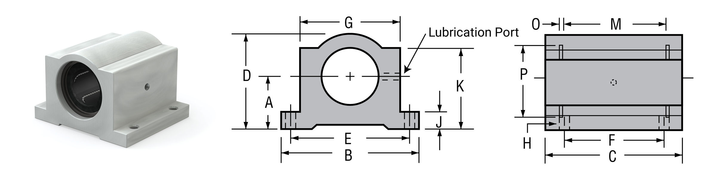
Dimensional Information
| Part No. | Nom. Brg. I.D. In. |
A Centerline +/- 0.001 |
B Width |
C Length |
D Height |
E +/- 0.010 |
F +/- 0.010 |
G Body Width |
H | J Flange Thick |
K | M GRV. Space |
O GRV. Width |
P GRV. Dia. |
Assem. WT. lb |
Load Ratings | ||
|---|---|---|---|---|---|---|---|---|---|---|---|---|---|---|---|---|---|---|
| Bolt | Hole | Dynamic C lb |
Static Co lb |
|||||||||||||||
| IPPS08G | 1/2 | 0.687 | 2.000 | 1.69 | 1.250 | 1.688 | 1.000 | 1.375 | #6 | 5/32" | 0.250 | 1.125 | 1.250 | 0.046 | 0.931 | 0.200 | 230 | 159 |
| IPPS10G | 5/8 | 0.875 | 2.500 | 1.94 | 1.625 | 2.125 | 1.125 | 1.750 | #8 | 3/16" | 0.281 | 1.438 | 1.500 | 0.056 | 1.197 | 0.500 | 400 | 264 |
| IPPS12G | 3/4 | 0.937 | 2.750 | 2.06 | 1.750 | 2.375 | 1.250 | 1.875 | #8 | 3/16" | 0.313 | 1.563 | 1.625 | 0.056 | 1.330 | 0.600 | 470 | 372 |
| IPPS16G | 1 | 1.187 | 3.250 | 2.81 | 2.188 | 2.875 | 1.750 | 2.375 | #10 | 7/32" | 0.375 | 1.938 | 2.250 | 0.068 | 1.671 | 1.200 | 850 | 667 |
| IPPS20G | 1-1/4 | 1.500 | 4.000 | 3.63 | 2.813 | 3.500 | 2.000 | 3.000 | #10 | 7/32" | 0.438 | 2.500 | 2.625 | 0.068 | 2.122 | 2.500 | 1230 | 992 |
| IPPS24G | 1-1/2 | 1.750 | 4.750 | 4.00 | 3.250 | 4.125 | 2.500 | 3.500 | 1/4" | 9/32" | 0.500 | 2.875 | 3.000 | 0.086 | 2.519 | 3.800 | 1480 | 1258 |
| IPPS32G | 2 | 2.125 | 6.000 | 5.00 | 4.063 | 5.250 | 3.250 | 4.500 | 3/8" | 13/32" | 0.625 | 3.625 | 4.000 | 0.103 | 3.182 | 2430 | 2165 | |
Notes:
(1) All IPPS series pillow blocks use IPS series self-aligning bearings.
(2) Includes grease zerk fittings for relubrication.
Open Pillow Blocks IPPSN
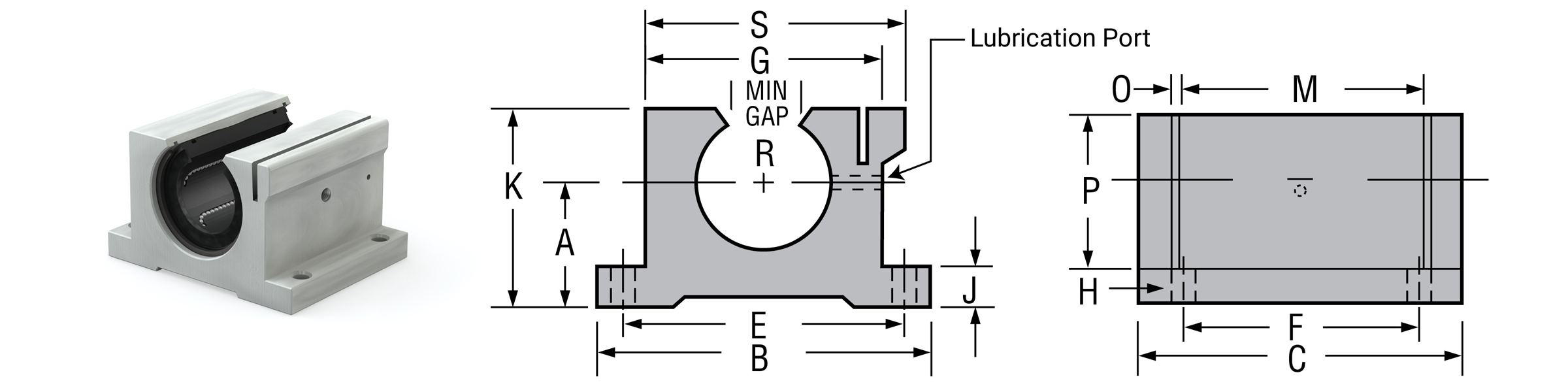
Dimensional Information
| Part No. | Nom. Brg. I.D. In. |
A Centraline +/-0.001 |
B Width |
C Length |
E +/-0.010 |
F +/-0.010 |
G Body Width |
H | J Flange Thick |
K Height |
M GRV. Space |
O GRV. Width |
P GRV. Dia. |
R Min Open |
S Overall Width |
Assem. W.T. lb. |
Load Rating | ||
|---|---|---|---|---|---|---|---|---|---|---|---|---|---|---|---|---|---|---|---|
| Bolt | Hole | Dynamic C lb. |
Static Co lb. |
||||||||||||||||
| IPPSN08G | 1/2 | 0.687 | 2.000 | 1.50 | 1.688 | 1.000 | 1.375 | #6 | 5/32" | 0.250 | 1.125 | 1.250 | 0.046 | 0.931 | 0.313 | 1.438 | 0.200 | 230 | 159 |
| IPPSN10G | 5/8 | 0.875 | 2.500 | 1.75 | 2.125 | 1.125 | 1.750 | #8 | 3/16" | 0.281 | 1.438 | 1.500 | 0.056 | 1.197 | 0.375 | 1.813 | 0.400 | 400 | 264 |
| IPPSN12G | 3/4 | 0.937 | 2.750 | 1.88 | 2.375 | 1.250 | 1.875 | #8 | 3/16" | 0.313 | 1.563 | 1.625 | 0.056 | 1.330 | 0.438 | 1.938 | 0.500 | 470 | 372 |
| IPPSN16G | 1 | 1.187 | 3.250 | 2.63 | 2.875 | 1.750 | 2.375 | #10 | 7/32" | 0.375 | 1.938 | 2.250 | 0.068 | 1.671 | 0.563 | 2.438 | 1.000 | 850 | 667 |
| IPPSN20G | 1-1/4 | 1.500 | 4.000 | 3.38 | 3.500 | 2.000 | 3.000 | #10 | 7/32" | 0.438 | 2.500 | 2.625 | 0.068 | 2.122 | 0.625 | 3.125 | 2.100 | 1230 | 992 |
| IPPSN24G | 1-1/2 | 1.750 | 4.750 | 3.75 | 4.125 | 2.500 | 3.500 | 1/4" | 9/32" | 0.500 | 2.875 | 3.000 | 0.086 | 2.519 | 0.750 | 3.625 | 3.200 | 1480 | 1258 |
| IPPSN32G | 2 | 2.125 | 6.000 | 4.75 | 5.250 | 3.250 | 43.500 | 3/8" | 13/32" | 0.625 | 3.625 | 4.000 | 0.103 | 3.182 | 1.000 | 4.688 | 2430 | 2165 | |
Notes:
(1) All IPPS series pillow blocks use IPS series self-aligning bearings.
(2) Includes grease zerk fittings for relubrication.
Linear Ball Bearings Precision Plus Twin Pillow Blocks with Lubrication Ports
Closed Twin Pillow Blocks IPPSW
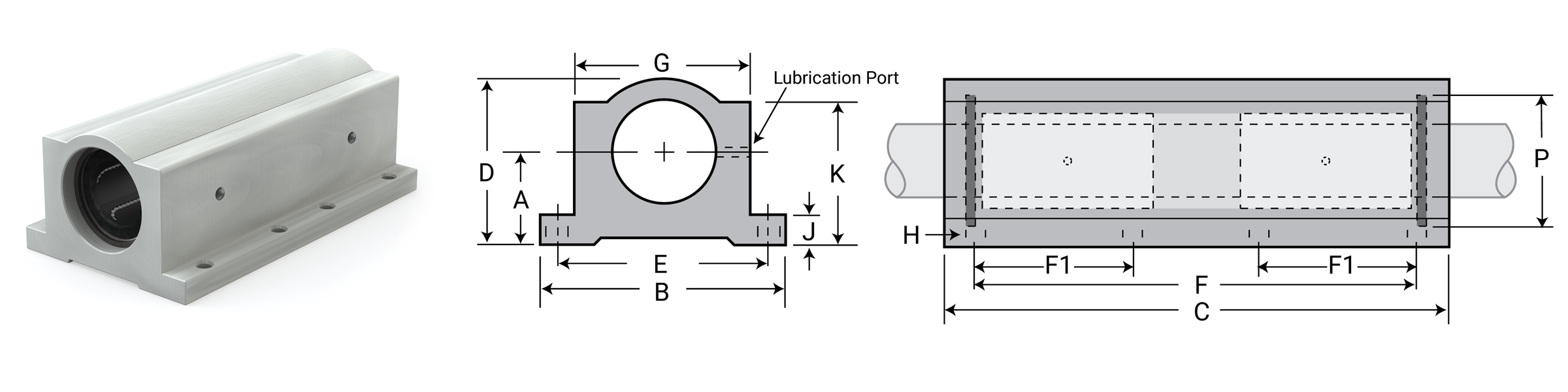
Dimensional Information
| Part No. | Nom. Brg. I.D. In. |
A Centerline +/- 0.001 |
B Width |
C Length |
D Height |
E +/- 0.010 |
F +/- 0.010 |
F1 +/- 0.010 |
G Body Width |
H | J Flange Thick |
K | P GRV. Dia. |
Assem. WT. lb |
Load Ratings | ||
|---|---|---|---|---|---|---|---|---|---|---|---|---|---|---|---|---|---|
| Bolt | Hole | Dynamic C lb |
Static Co lb |
||||||||||||||
| IPPSW08G | 1/2 | 0.687 | 2.000 | 3.500 | 1.250 | 1.688 | 2.500 | 1.000 | 1.375 | #6 | 5/32" | 0.250 | 1.125 | 0.931 | 0.50 | 460 | 318 |
| IPPSW10G | 5/8 | 0.875 | 2.500 | 4.000 | 1.625 | 2.125 | 3.000 | 1.125 | 1.750 | #8 | 3/16" | 0.281 | 1.438 | 1.197 | 1.00 | 800 | 528 |
| IPPSW12G | 3/4 | 0.937 | 2.750 | 4.500 | 1.750 | 2.375 | 3.500 | 1.250 | 1.875 | #8 | 3/16" | 0.313 | 1.563 | 1.330 | 1.20 | 940 | 744 |
| IPPSW16G | 1 | 1.187 | 3.250 | 6.000 | 2.188 | 2.875 | 4.500 | 1.750 | 2.375 | #10 | 7/32" | 0.375 | 1.938 | 1.671 | 2.20 | 1700 | 1334 |
| IPPSW20G | 1-1/4 | 1.500 | 4.000 | 7.500 | 2.813 | 3.500 | 5.500 | 2.000 | 3.000 | #10 | 7/32" | 0.438 | 2.500 | 2.122 | 4.50 | 2460 | 1984 |
| IPPSW24G | 1-1/2 | 1.750 | 4.750 | 9.000 | 3.250 | 4.125 | 6.500 | 2.500 | 3.500 | 1/4" | 9/32" | 0.500 | 2.875 | 2.519 | 6.30 | 2960 | 2516 |
| IPPSW32G | 2 | 2.125 | 6.000 | 10.000 | 4.063 | 5.250 | 8.250 | 3.250 | 4.500 | 3/8" | 13/32" | 0.625 | 3.182 | 2.519? | 4860 | 4330 | |
Notes:
(1) All IPPS series pillow blocks use IPS series self-aligning bearings.
(2) Includes grease zerk fittings for relubrication.
Open Twin Pillow Blocks IPPSWN
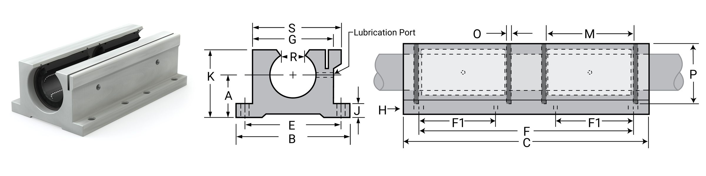
Dimensional Information
| Part No. | Nom. Brg. I.D. In. |
A Centraline +/-0.001 |
B Width |
C Length |
E +/-0.010 |
F +/-0.010 |
F1 +/-0.010 |
G Body Width |
H | J Flange Thick |
K Height |
M GRV. Space |
O GRV. Width |
P GRV. Dia. |
R Min Open |
S Overall Width |
Assem. W.T. lb. |
Load Ratings | ||
|---|---|---|---|---|---|---|---|---|---|---|---|---|---|---|---|---|---|---|---|---|
| Bolt | Hole | Dynamic C lb. |
Static Co lb. |
|||||||||||||||||
| IPPSWN08G | 1/2 | 0.687 | 2.000 | 3.500 | 1.688 | 2.500 | 1.000 | 1.375 | #6 | 5/32" | 0.250 | 1.125 | 1.250 | 0.046 | 0.931 | 0.313 | 1.438 | 0.40 | 460 | 318 |
| IPPSWN10G | 5/8 | 0.875 | 2.500 | 4.000 | 2.125 | 3.000 | 1.125 | 1.750 | #8 | 3/16" | 0.281 | 1.438 | 1.500 | 0.056 | 1.197 | 0.375 | 1.813 | 0.80 | 800 | 528 |
| IPPSWN12G | 3/4 | 0.937 | 2.750 | 4.500 | 2.375 | 3.500 | 1.250 | 1.875 | #8 | 3/16" | 0.313 | 1.563 | 1.625 | 0.056 | 1.330 | 0.438 | 1.938 | 1.00 | 940 | 744 |
| IPPSWN16G | 1 | 1.187 | 3.250 | 6.000 | 2.875 | 4.500 | 1.750 | 2.375 | #10 | 7/32" | 0.375 | 1.938 | 2.250 | 0.068 | 1.671 | 0.563 | 2.438 | 2.00 | 1700 | 1334 |
| IPPSWN20G | 1-1/4 | 1.500 | 4.000 | 7.500 | 3.500 | 5.500 | 2.000 | 3.000 | #10 | 7/32" | 0.438 | 2.500 | 2.625 | 0.068 | 2.122 | 0.625 | 3.125 | 4.00 | 2460 | 1984 |
| IPPSWN24G | 1-1/2 | 1.750 | 4.750 | 9.000 | 4.125 | 6.500 | 2.500 | 3.500 | 1/4" | 9/32" | 0.500 | 2.875 | 3.000 | 0.086 | 2.519 | 0.750 | 3.625 | 6.00 | 2960 | 2516 |
| IPPSWN32G | 2 | 2.125 | 6.000 | 10.000 | 5.250 | 8.250 | 3.250 | 4.500 | 3/8" | 13/32" | 0.625 | 3.625 | 4.000 | 0.103 | 3.182 | 1.000 | 4.688 | 4860 | 4330 | |
Notes:
(1) All IPPS series pillow blocks use IPS series self-aligning bearings.
(2) Includes grease zerk fittings for relubrication.
Linear Ball Bearings Precision Pillow Blocks
Ball Bearings - Closed Pillow Blocks IPP
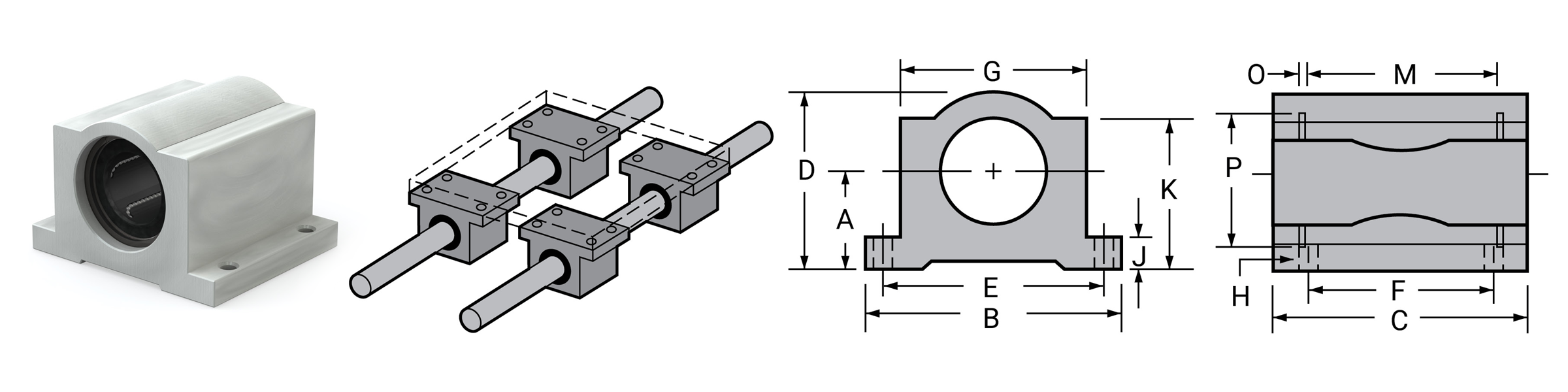
Dimensional Information
| Part No. Precision |
Nom. Brg. I.D. In. |
A Centerline +/- 0.001 |
B Width |
C Length |
D Height |
E +/- 0.010 |
F +/- 0.010 |
G Body Width |
H | J Flange Thick |
K Height |
M GRV. Space |
O GRV. Width |
P GRV. Dia. |
Smallery Ret. Ring Part No. |
Assem W.T. lb. |
Load Ratings lb. |
||
|---|---|---|---|---|---|---|---|---|---|---|---|---|---|---|---|---|---|---|---|
| Bolt | Hole | Dynamic C |
Static Co |
||||||||||||||||
| IPP04G | 1/4 | 0.437 | 1.625 | 1.19 | 0.813 | 1.312 | 0.750 | 1.000 | #6 | 5/32" | 0.188 | 0.750 | 0.750 | 0.039 | 0.532 | WH-51 | 0.099 | 46 | 59 |
| IPP06G | 3/8 | 0.500 | 1.750 | 1.31 | 0.938 | 1.437 | 0.875 | 1.125 | #6 | 5/32" | 0.188 | 0.875 | 0.875 | 0.039 | 0.665 | WH-65 | 0.129 | 50 | 70 |
| IPP08G | 1/2 | 0.687 | 2.000 | 1.69 | 1.250 | 1.688 | 1.000 | 1.375 | #6 | 5/32" | 0.250 | 1.125 | 1.250 | 0.046 | 0.931 | WH-90 | 0.250 | 114 | 176 |
| IPP10G | 5/8 | 0.875 | 2.500 | 1.94 | 1.625 | 2.125 | 1.125 | 1.750 | #8 | 3/16" | 0.281 | 1.438 | 1.500 | 0.056 | 1.197 | WH-115 | 0.500 | 174 | 265 |
| IPP12G | 3/4 | 0.937 | 2.750 | 2.06 | 1.750 | 2.375 | 1.250 | 1.875 | #8 | 3/16" | 0.313 | 1.563 | 1.625 | 0.056 | 1.330 | WH-128 | 0.580 | 193 | 307 |
| IPP16G | 1 | 1.187 | 3.250 | 2.81 | 2.188 | 2.875 | 1.750 | 2.375 | #10 | 7/32" | 0.375 | 1.938 | 2.250 | 0.068 | 1.671 | WH-156 | 1.000 | 220 | 352 |
| IPP20G | 1-1/4 | 1.500 | 4.000 | 3.63 | 2.813 | 3.500 | 2.000 | 3.000 | #10 | 7/32" | 0.438 | 2.500 | 2.625 | 0.068 | 2.122 | WH-200 | 2.000 | 352 | 615 |
| IPP24G | 1-1/2 | 1.750 | 4.750 | 4.00 | 3.250 | 4.125 | 2.500 | 3.500 | 1/4" | 9/32" | 0.500 | 2.875 | 3.000 | 0.086 | 2.519 | WH-237 | 3.000 | 490 | 903 |
| IPP32G | 2 | 2.125 | 6.000 | 5.00 | 4.063 | 5.250 | 3.250 | 4.500 | 3/8" | 13/32" | 0.625 | 3.625 | 4.000 | 0.103 | 3.182 | WH-300 | 6.500 | 858 | 1784 |
Notes:
(1) Pre-assembled IPP series pillow blocks include self-aligning housing and IP series precision bearings.
(2) Straight bore, "B" option must be ordered for non-self aligning pillow block assemblies.
Ball Bearings - Open Pillow Blocks IPPN
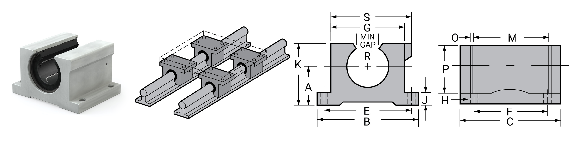
Dimensional Information
| Part No. Precision |
Nom. Brg. I.D. In. |
A Centerline +/- 0.001 |
B Width +/- 0.001 |
C Length |
E +/- 0.010 |
F +/- 0.010 |
G Body Width |
H | J Flange Thick |
K Height |
M GRV. Space |
O GRV. Width |
P GRV. Dia. |
R MIN. Open |
S Overall Width |
Eaton Ret. Ring Part No. |
Assem W.T. lb. |
Load Ratings lb. |
||
|---|---|---|---|---|---|---|---|---|---|---|---|---|---|---|---|---|---|---|---|---|
| Bolt | Hole | Dynamic C |
Static Co |
|||||||||||||||||
| IPPN08G | 1/2 | 0.687 | 2.00 | 1.50 | 1.688 | 1.000 | 1.375 | #6 | 5/32" | 0.250 | 1.125 | 1.250 | 0.046 | 0.931 | 0.313 | 1.438 | MNAN-87 | 0.25 | 114 | 176 |
| IPPN10G | 5/8 | 0.875 | 2.50 | 1.75 | 2.125 | 1.125 | 1.750 | #8 | 3/16" | 0.281 | 1.438 | 1.500 | 0.056 | 1.197 | 0.375 | 1.813 | MNAN-112 | 0.50 | 174 | 265 |
| IPPN12G | 3/4 | 0.937 | 2.75 | 1.88 | 2.375 | 1.250 | 1.875 | #8 | 3/16" | 0.313 | 1.563 | 1.625 | 0.056 | 1.330 | 0.438 | 1.938 | MNAN-125 | 0.58 | 193 | 307 |
| IPPN16G | 1 | 1.187 | 3.25 | 2.63 | 2.875 | 1.750 | 2.375 | #10 | 7/32" | 0.375 | 1.938 | 2.250 | 0.068 | 1.671 | 0.563 | 2.438 | MNAN-156 | 1.00 | 220 | 352 |
| IPPN20G | 1-1/4 | 1.500 | 4.00 | 3.38 | 3.500 | 2.000 | 3.000 | #10 | 7/32" | 0.438 | 2.500 | 2.625 | 0.068 | 2.122 | 0.625 | 3.125 | MNAN-200 | 2.00 | 352 | 615 |
| IPPN24G | 1-1/2 | 1.750 | 4.75 | 3.75 | 4.125 | 2.500 | 3.500 | 1/4" | 9/32" | 0.500 | 2.875 | 3.000 | 0.086 | 2.519 | 0.750 | 3.625 | MNAN-237 | 3.00 | 490 | 903 |
| IPPN32G | 2 | 2.125 | 6.00 | 4.75 | 5.250 | 3.250 | 4.500 | 3/8" | 13/32" | 0.625 | 3.625 | 4.000 | 0.103 | 3.182 | 1.000 | 4.688 | MNAN-300 | 6.50 | 858 | 1784 |
Notes:
(1) Pre-assembled IPP series pillow blocks include self-aligning housing and IP series precision bearings.
(2) Straight bore, "B" option must be ordered for non-self aligning pillow block assemblies.
⚠ Only certified Simplicity 60 Plus Shafting provides maximum linear bearing performance.
Linear Ball Bearings Precision Twin Pillow Blocks
Ball Bearings - Twin Closed Pillow Blocks IPPW
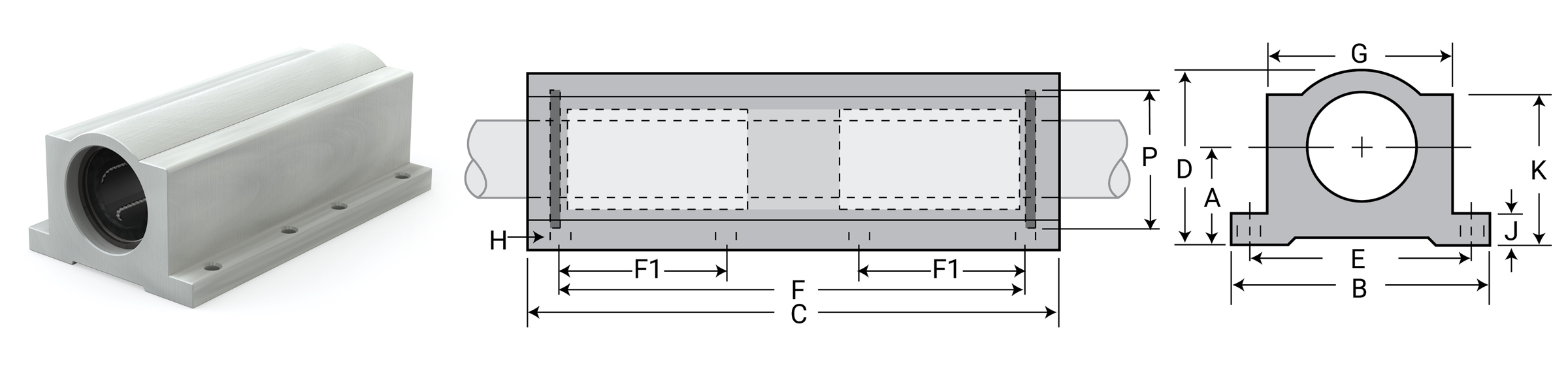
Dimensional Information
| Part No. Precision |
Nom. Brg. Dia. In. |
A Centerline +/- 0.001 |
B Width |
C Length |
D Height |
E +/- 0.010 |
F +/- 0.010 |
F1 +/- 0.010 |
G Body Width |
H | J Thick |
K Height |
P GRV. Dia. |
Smallery Ret. Ring Part No. |
Assem W.T. lb. |
Load Ratings lb. |
||
|---|---|---|---|---|---|---|---|---|---|---|---|---|---|---|---|---|---|---|
| Bolt | Hole | Dynamic C |
Static Co |
|||||||||||||||
| IPPW04G | 1/4 | 0.437 | 1.625 | 2.50 | 0.813 | 1.312 | 2.000 | .750 | 1.000 | #6 | 5/32" | 0.188 | 0.750 | 0.532 | WH-51 | 0.197 | 92 | 118 |
| IPPW06G | 3/8 | 0.500 | 1.750 | 2.75 | 0.938 | 1.437 | 2.250 | .875 | 1.125 | #6 | 5/32" | 0.188 | 0.875 | 0.665 | WH-65 | 0.258 | 100 | 140 |
| IPPW08G | 1/2 | 0.687 | 2.000 | 3.50 | 1.250 | 1.688 | 2.500 | 1.000 | 1.375 | #6 | 5/32" | 0.250 | 1.125 | 0.931 | WH-90 | 0.500 | 228 | 352 |
| IPPW10G | 5/8 | 0.875 | 2.500 | 4.00 | 1.625 | 2.125 | 3.000 | 1.125 | 1.750 | #8 | 3/16" | 0.281 | 1.438 | 1.197 | WH-115 | 1.000 | 348 | 530 |
| IPPW12G | 3/4 | 0.937 | 2.750 | 4.50 | 1.750 | 2.375 | 3.500 | 1.250 | 1.875 | #8 | 3/16" | 0.313 | 1.563 | 1.330 | WH-128 | 1.125 | 386 | 614 |
| IPPW16G | 1 | 1.187 | 3.250 | 6.00 | 2.188 | 2.875 | 4.500 | 1.750 | 2.375 | #10 | 7/32" | 0.375 | 1.938 | 1.671 | WH-156 | 2.188 | 440 | 704 |
| IPPW20G | 1-1/4 | 1.500 | 4.000 | 7.50 | 2.813 | 3.500 | 5.500 | 2.000 | 3.000 | #10 | 7/32" | 0.438 | 2.500 | 2.122 | WH-200 | 4.250 | 704 | 1230 |
| IPPW24G | 1-1/2 | 1.750 | 4.750 | 9.00 | 3.250 | 4.125 | 6.500 | 2.500 | 3.500 | 1/4" | 9/32" | 0.500 | 2.875 | 2.519 | WH-237 | 6.375 | 980 | 1806 |
| IPPW32G | 2 | 2.125 | 6.000 | 10.00 | 4.063 | 5.250 | 8.250 | 3.250 | 4.500 | 3/8" | 13/32" | 0.625 | 3.625 | 3.182 | WH-300 | 13.500 | 1716 | 3568 |
Notes:
(1) Pre-assembled IPP series pillow blocks include self-aligning housing and IP series precision bearings.
(2) Straight bore, "B" option must be ordered for non-self aligning pillow block assemblies.
Ball Bearings - Twin Open Pillow Blocks IPPWN
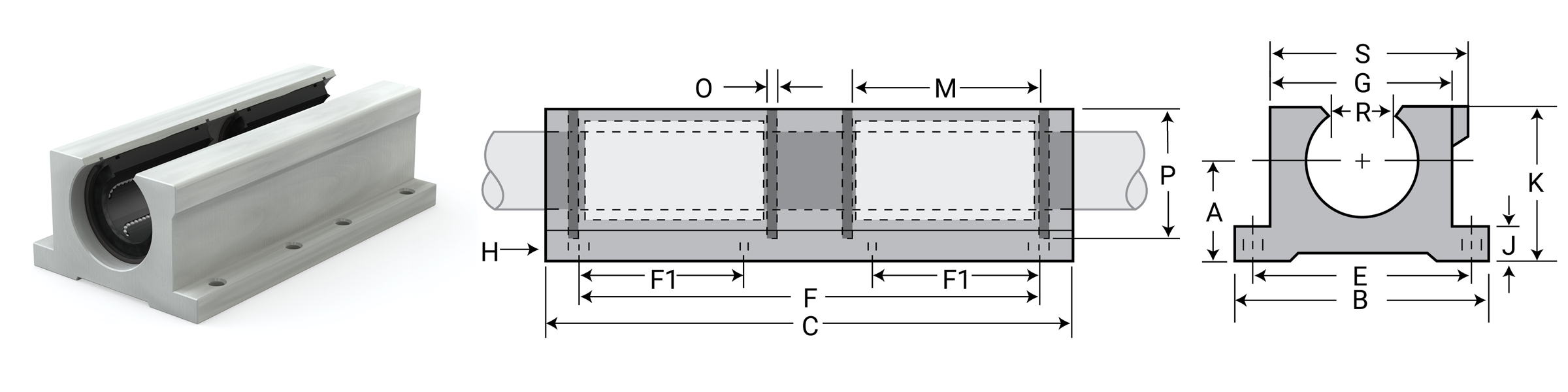
Dimensional Information
| Part No. Precision |
Nom. Brg. Dia. In. |
A Centerline +/- 0.001 |
B Width |
C Length |
E +/- 0.010 |
F +/- 0.010 |
F1 +/- 0.010 |
G Body Width |
H | J Flange Thick |
K Height |
M GRV. Space |
O GRV. Wide |
P GRV. Dia. |
R MIN. Open |
S Overall Width |
Eaton Ret. Ring Part No. |
Assem W.T. lb. |
Load Ratings lb. |
||
|---|---|---|---|---|---|---|---|---|---|---|---|---|---|---|---|---|---|---|---|---|---|
| Bolt | Hole | Dynamic C |
Static Co |
||||||||||||||||||
| IPPWN08G | 1/2 | 0.687 | 2.00 | 3.500 | 1.688 | 2.500 | 1.000 | 1.375 | #6 | 5/32" | 0.250 | 1.125 | 1.250 | 0.046 | 0.931 | 0.313 | 1.438 | MNAN-87 | 0.400 | 228 | 352 |
| IPPWN10G | 5/8 | 0.875 | 2.50 | 4.000 | 2.125 | 3.000 | 1.125 | 1.750 | #8 | 3/16" | 0.281 | 1.438 | 1.500 | 0.056 | 1.197 | 0.375 | 1.813 | MNAN-112 | 0.910 | 348 | 530 |
| IPPWN12G | 3/4 | 0.937 | 2.75 | 4.500 | 2.375 | 3.500 | 1.250 | 1.875 | #8 | 3/16” | 0.313 | 1.563 | 1.625 | 0.056 | 1.330 | 0.438 | 1.938 | MNAN-125 | 1.060 | 386 | 614 |
| IPPWN16G | 1 | 1.187 | 3.25 | 6.000 | 2.875 | 4.500 | 1.750 | 2.375 | #10 | 7/32" | 0.375 | 1.938 | 2.250 | 0.068 | 1.671 | 0.563 | 2.438 | MNAN-156 | 1.970 | 440 | 704 |
| IPPWN20G | 1-1/4 | 1.500 | 4.00 | 7.500 | 3.500 | 5.500 | 2.000 | 3.000 | #10 | 7/32” | 0.438 | 2.500 | 2.625 | 0.068 | 2.122 | 0.625 | 3.125 | MNAN-200 | 3.725 | 704 | 1230 |
| IPPWN24G | 1-1/2 | 1.750 | 4.75 | 9.000 | 4.125 | 6.500 | 2.500 | 3.500 | 1/4" | 9/32" | 0.500 | 2.875 | 3.000 | 0.086 | 2.519 | 0.750 | 3.625 | MNAN-237 | 5.800 | 980 | 1806 |
| IPPWN32G | 2 | 2.125 | 6.00 | 10.00 | 5.250 | 8.250 | 3.250 | 4.500 | 3/8" | 13/32" | 0.625 | 3.625 | 4.000 | 0.103 | 3.182 | 1.000 | 4.688 | MNAN-300 | 12.125 | 1716 | 3568 |
Notes:
(1) Pre-assembled IPP series pillow blocks include self-aligning housing and IP series precision bearings.
(2) Straight bore, "B" option must be ordered for non-self aligning pillow block assemblies.
Linear Ball Bearings Double Wide
Double Wide Ball Bearings IP-W
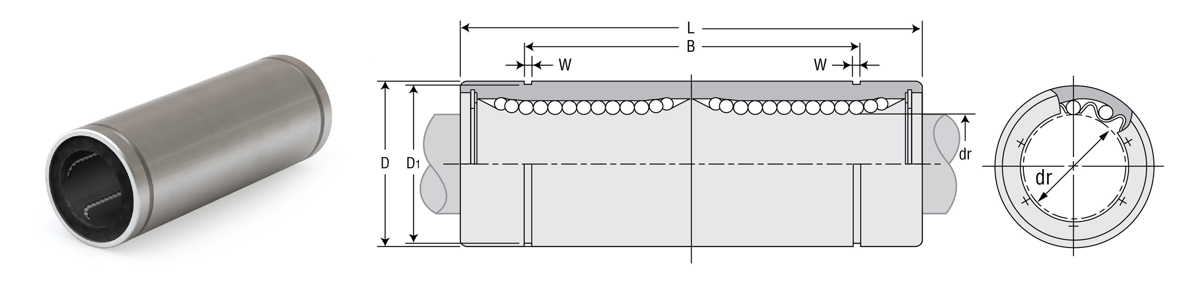
Dimensional Information
| Part No. Standard Closed |
Nominal Diameter | Ball Circuit | Weight G |
Major Dimensions & Tolerances | |||||||
|---|---|---|---|---|---|---|---|---|---|---|---|
| Size In. |
dr In. |
Tolerance In. |
D In. |
Tolerance In. |
L In. |
Tolerance In. |
B In. |
Tolerance In. |
|||
| IP04GW | 1/4 | 0.25 | 0/-0.0004 | 4 | 18 | 0.5000 | 0/-0.00050 | 1.3750 | 0/-0.012 | 1.0220 | 0/-0.012 |
| IP06GW | 3/8 | 0.375 | 0/-0.0004 | 4 | 28 | 0.6250 | 0/-0.00065 | 1.5938 | 0/-0.012 | 1.2716 | 0/-0.012 |
| IP08GW | 1/2 | 0.5000 | 0/-0.0004 | 4 | 80 | 0.8750 | 0/-0.00065 | 2.3750 | 0/-0.012 | 1.9250 | 0/-0.012 |
| IP10GW | 5/8 | 0.6250 | 0/-0.0004 | 4 | 160 | 1.1250 | 0/-0.00065 | 2.8125 | 0/-0.012 | 2.2079 | 0/-0.012 |
| IP12GW | 3/4 | 0.7500 | 0/-0.0005 | 5 | 195 | 1.2500 | 0/-0.00075 | 3.0937 | 0/-0.012 | 2.3314 | 0/-0.012 |
| IP16GW | 1 | 1.0000 | 0/-0.0005 | 6 | 410 | 1.5625 | 0/-0.00075 | 4.2813 | 0/-0.016 | 3.5094 | 0/-0.16 |
| IP20GW | 1-1/4 | 1.2500 | 0/-0.0006 | 6 | 820 | 2.0000 | 0/-0.00090 | 5.0000 | 0/-0.016 | 4.0094 | 0/-0.16 |
| IP24GW | 1-1/2 | 1.5000 | 0/-0.0006 | 6 | 1250 | 2.3750 | 0/-0.00090 | 5.6875 | 0/-0.016 | 4.8236 | 0/-0.16 |
| IP32GW | 2 | 2.0000 | 0/-0.0006 | 6 | 2350 | 3.0000 | 0/-0.00100 | 7.7500 | 0/-0.016 | 6.3834 | 0/-0.16 |
| Part No. Standard Closed |
Nominal Diameter | Major Dimensions & Tolerances | Load Ratings | |||||
|---|---|---|---|---|---|---|---|---|
| Size In. |
dr In. |
Tolerance In. |
W In. |
D1 In. |
Max Eccentricity In. |
Dynamic C lb. |
Static Co lb. |
|
| IP04GW | 1/4 | 0.25 | 0/-0.0004 | 0.0390 | 0.4687 | 0.0006 | 72 | 119 |
| IP06GW | 3/8 | 0.375 | 0/-0.0004 | 0.0390 | 0.5880 | 0.0006 | 79 | 142 |
| IP08GW | 1/2 | 0.5000 | 0/-0.0004 | 0.0459 | 0.8209 | 0.0005 | 182 | 352 |
| IP10GW | 5/8 | 0.6250 | 0/-0.0004 | 0.0559 | 1.0590 | 0.0005 | 276 | 528 |
| IP12GW | 3/4 | 0.7500 | 0/-0.0005 | 0.0559 | 1.1760 | 0.0007 | 307 | 615 |
| IP16GW | 1 | 1.0000 | 0/-0.0005 | 0.0679 | 1.4687 | 0.0007 | 352 | 705 |
| IP20GW | 1-1/4 | 1.2500 | 0/-0.0006 | 0.0679 | 1.8859 | 0.0009 | 562 | 1234 |
| IP24GW | 1-1/2 | 1.5000 | 0/-0.0006 | 0.0859 | 2.2389 | 0.0009 | 771 | 1807 |
| IP32GW | 2 | 2.0000 | 0/-0.0006 | 0.1029 | 2.8379 | 0.0011 | 1366 | 3574 |
⚠ Only certified Simplicity 60 Plus Shafting provides maximum linear bearing performance.
Roller Pillow Block Bearings Overview
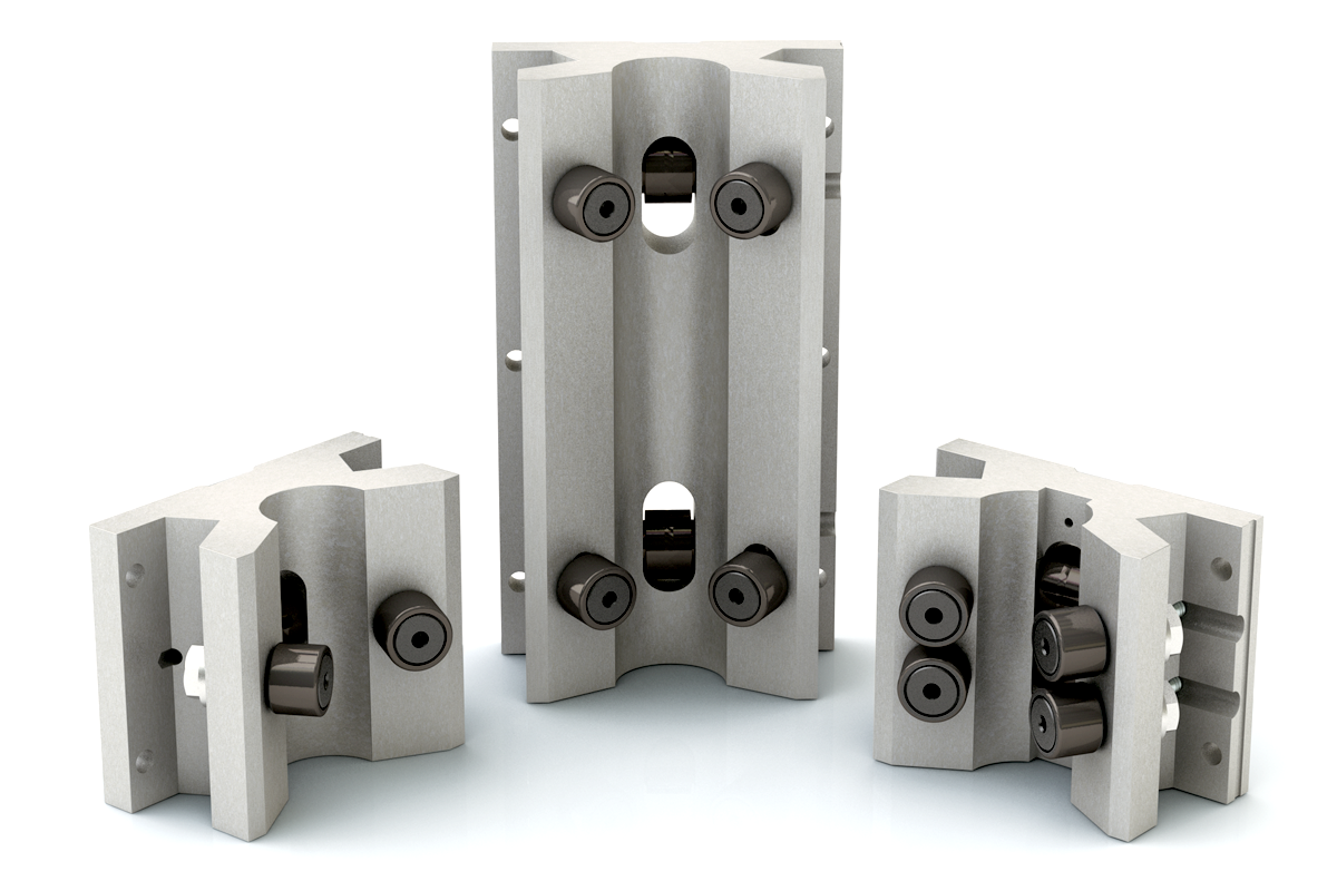
Roller Pillow Blocks
The Roller Pillow Block provides key performance benefits such as high load capacities, high speeds, and design compatibility—providing size interchangeability with industry standard blocks. In contaminated environments, the roller bearings push particulates out of the way or roll seamlessly over them. Large rollers in the Roller Pillow Block system are well suited for long travel applications, minimizing vibration and providing smooth and quiet travel over joined shafts.
The Roller Pillow Block solution is available for shaft diameters from 0.5”–3.0” and in three standard configurations; single, double, and twin. This provides dynamic load ratings ranging from 800 to 12500 pounds, a low coefficient of friction, and high speed capabilities.
The Roller Pillow Block system is well suited for a wide range of applications, including material handling, transfer lines, welding equipment, architectural and structural doors, and much more.
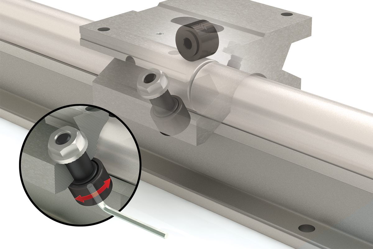
Eccentric bearing
adjustment enables
fine-tuned adjustments
Large cam follower navigates joined shafts and rail assemblies with ease
- Designed for high loads and/or speeds
- Loads up to 12,500 pounds
- Simplified installation and alignment
- Self-aligning
- Adjustable
- Superior for joined rail applications
- Standard mounting holes
- Interchangeability with industry standards
- Re-buildable
Reliability
- Large cam follower design with side seals delivers superior contaminant resistance
- Excels in long travel joined shafts or rail assemblies
- Accessories such as lubrication ports and scrapers available for ease of maintenance and maximum life
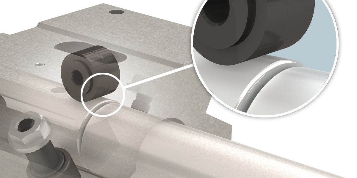
Roller pillow block’s large cam follower navigates joined shafts and rail assemblies with ease
Misalignment of shafts due to installation procedures or non-matched shafts can lead to premature or catastrophic ball bearing failures
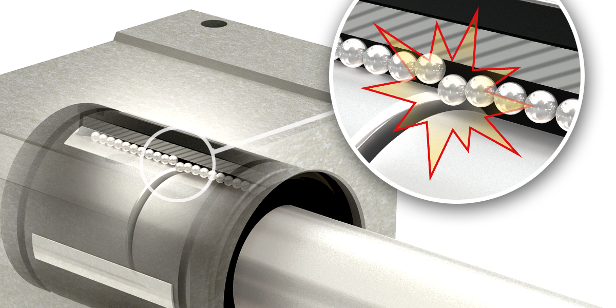
High Performance
- Speeds up to 2.5 times faster than a linear ball bearing pillow block
- Higher dynamic load capacity compared to industry standard linear ball bearing pillow blocks
- Smoother travel equals lower vibration and noise
Dynamic Load Ratings
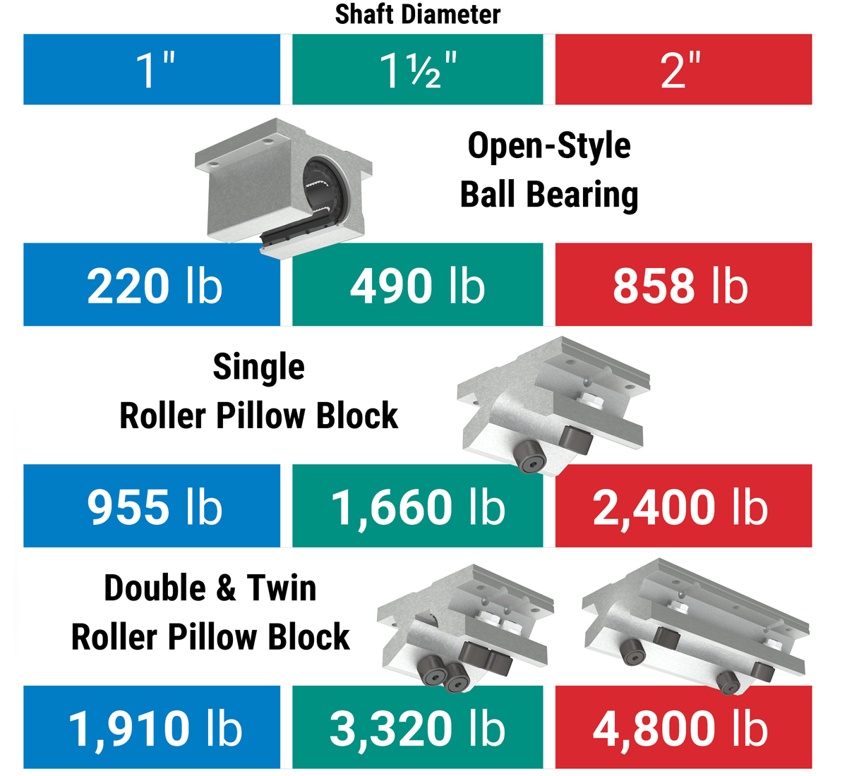
Dynamic load rating for a 3" shaft would be 6,260 lb for the Single Roller Pillow Block and 12,520 lb for the Double and Twin Roller Pillow Block.
Lower System Cost
- Simplified installation and alignment
- Floating pillow block option available accommodating up to 0.125" out-of-parallelism, reducing installation time and cost dramatically
- Simple eccentric bearing adjustment allows for tailored bearing fit to application requirements
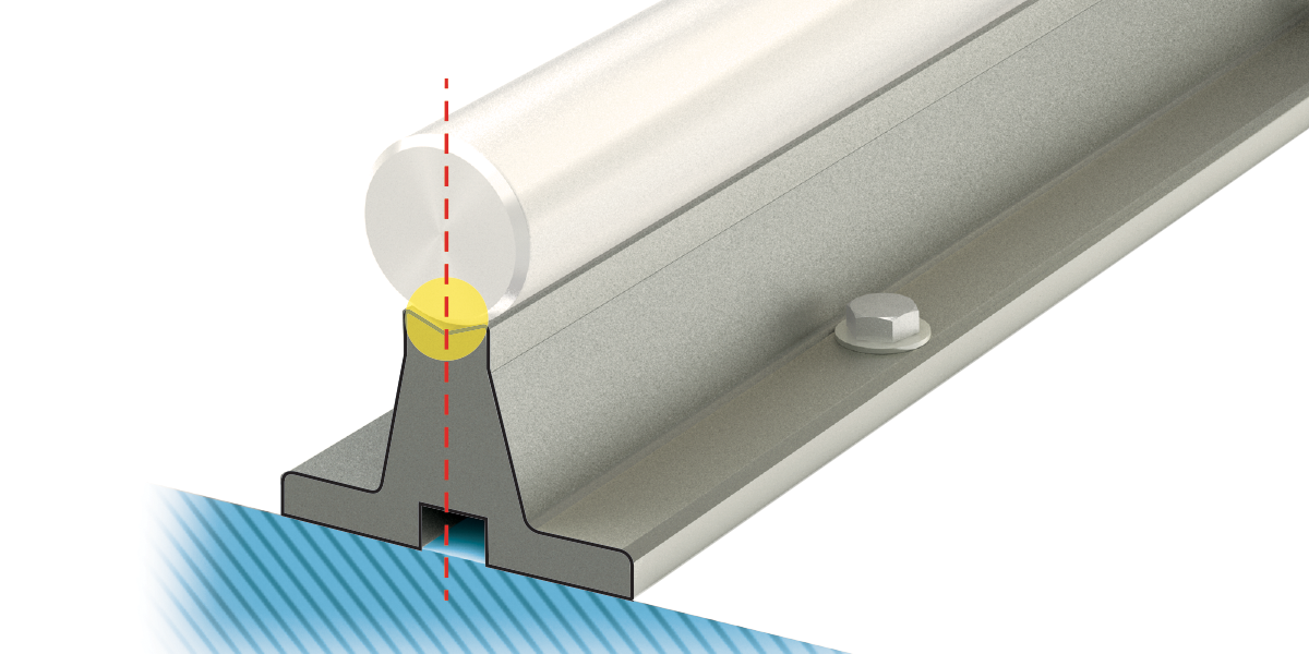
V-block shaped support rail design aligns shaft centerlines simplifying joined rail assemblies
Eccentric bearing adjustment enables fine-tuned adjustments
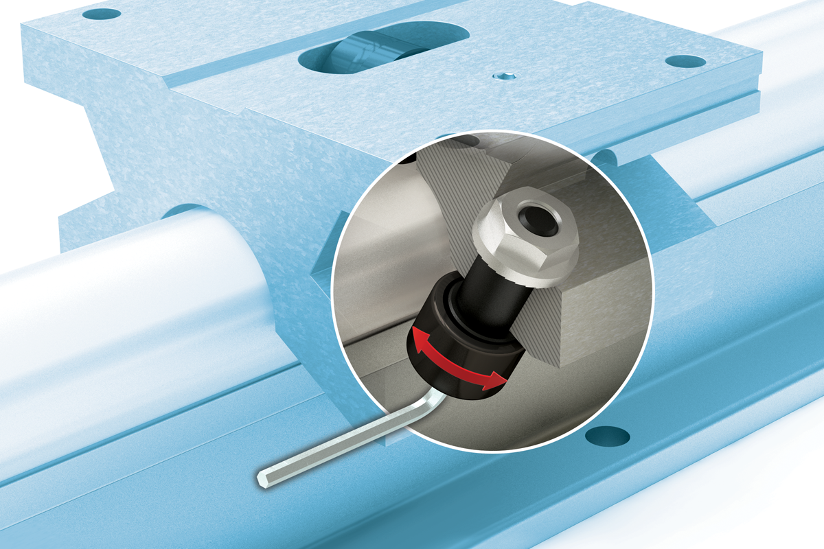
Design Compatibility
- Interchangeability to industry standard mounting holes and centerlines for linear bearing pillow blocks from leading competitors
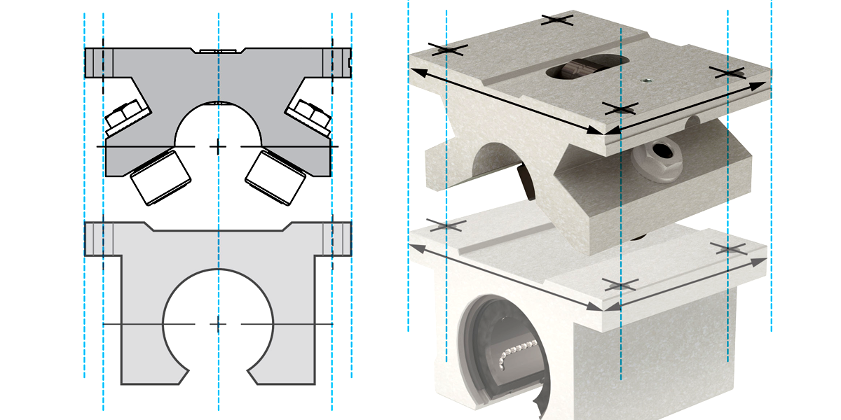
PBC Linear Roller Pillow Block is industry standard interchangeable, simplifying replacement and lowering costs
Note: When a linear ball bearing failure occurs, the shafting is easily damaged and needs to be replaced. When using the roller pillow block, that is not always the case. Consult factory for details.
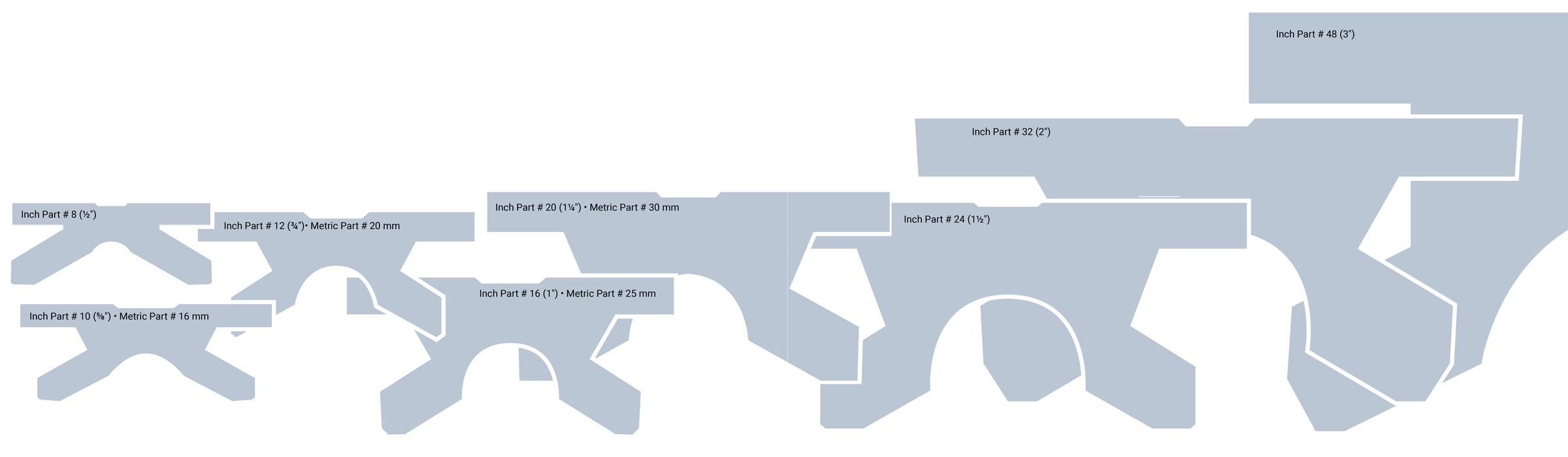
Roller Pillow Block Applications
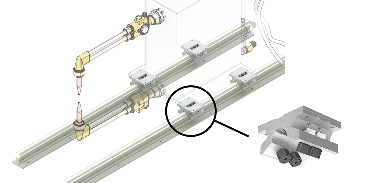
Welding Machines
Roller Pillow Blocks are corrosion resistant and handle loads up to 12,500 lbs, providing the industrial strength linear motion required in welding applications. The low-friction rollers easily navigate joined or misaligned shafts and also account for shaft deflection.
Industrial Stop Gauge & Push Feed System
The twin Roller Pillow Block provides the rigidity of a heavy duty bearing system for band saws, punches, bending machines, and brakes. Double and twin Roller Pillow Blocks are ideal for applications requiring high load capacities with long life.
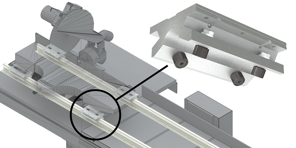
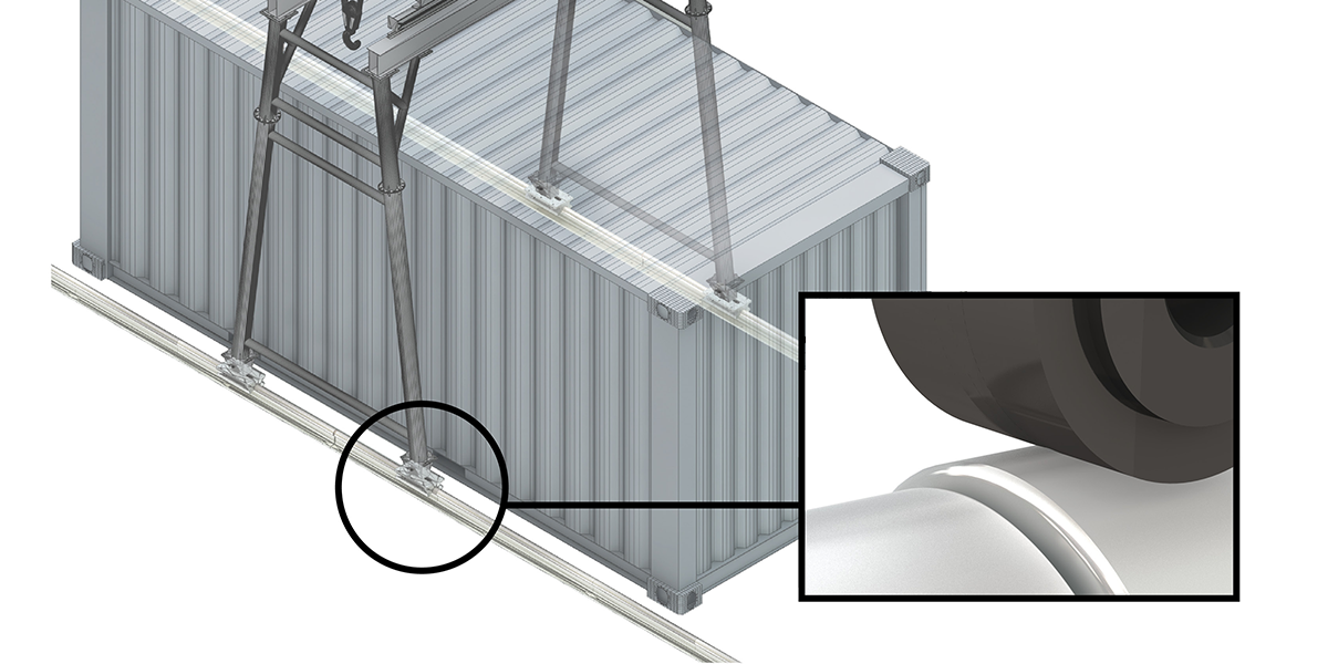
Rack Systems & Industrial Container Mobility
The Roller Pillow Block system carries heavy loads and easily maneuvers over joined or misaligned shafts over long travels. The system is corrosion resistant and provides high speeds and rigidity in the toughest applications.
Roller Bearings move smoothly over misaligned and joined shafts over long travels.
Sliding Doors
Roller Pillow Block systems provide smooth and quiet travel in a wide range of environments.
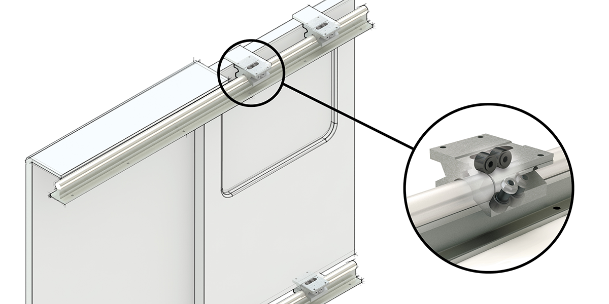
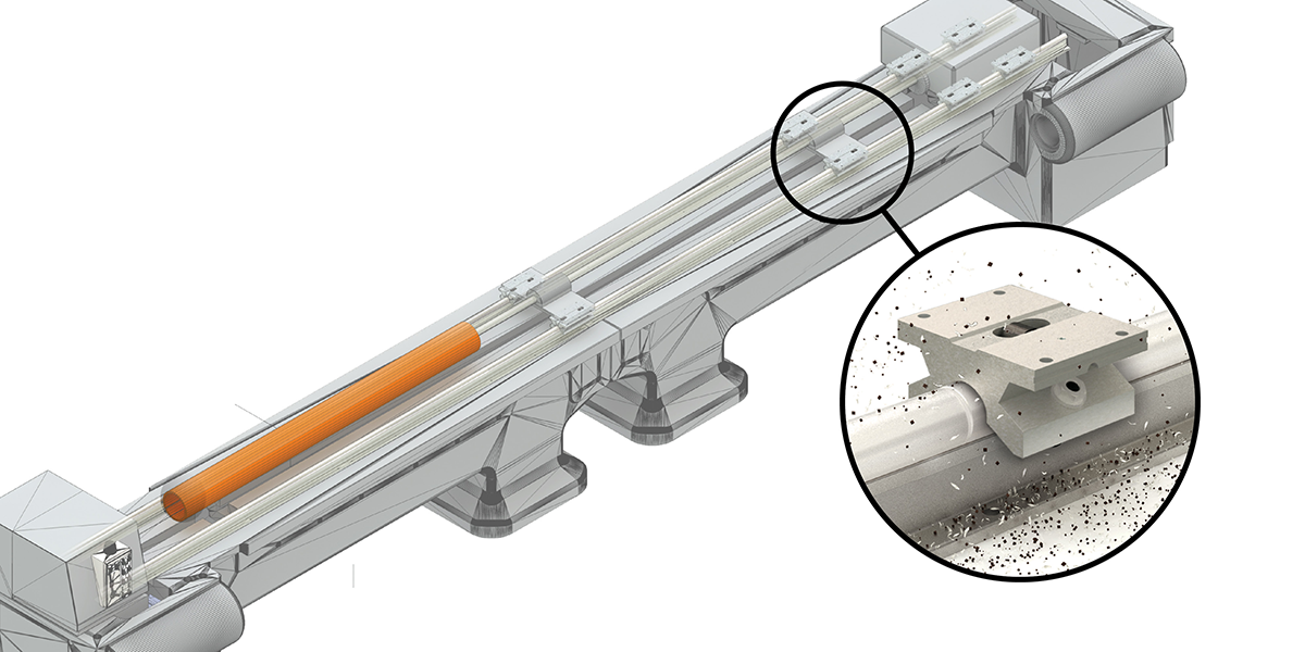
Pipe Mill
Roller Pillow Blocks provide smooth linear motion in the toughest environments. Large cam followers, equipped with side seals, deliver industrial strength performance over long travel lengths and excel in dirty environments.
Roller Pillow Block Bearings
Single Roller Pillow Block SPB-OPN
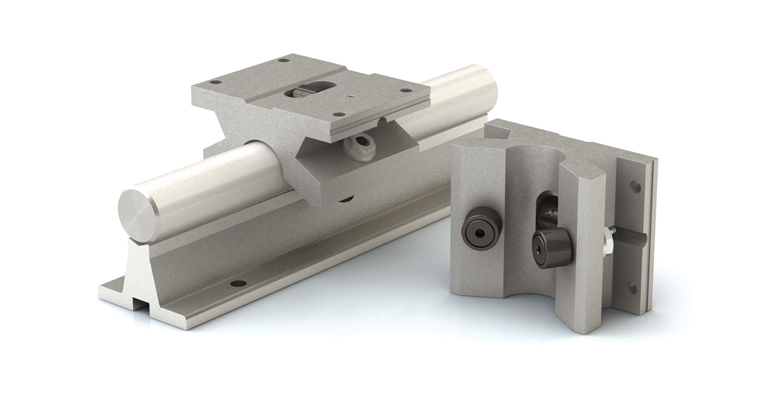
Low friction single Roller Pillow Blocks are selected for standard linear movement or for situations with shaft deflection. Self-aligning Roller Pillow Blocks can handle a half of a degree in misalignment.
Dimensions and Load Ratings Inch Shafting
| Part No. | Shaft Diameter in. |
DYN. Load Rating lb. |
Weight lb. |
A +-0.003 |
B in. |
C in. |
D in. |
E +-0.005 |
F +-0.005 |
G in. |
H | J in. |
K in. |
|
|---|---|---|---|---|---|---|---|---|---|---|---|---|---|---|
| Bolt | Hole | |||||||||||||
| SPB-08-OPN | 1/2 | 400 | 0.40 | 0.687 | 2.000 | 1.500 | 1.156 | 1.688 | 1.000 | 1.000 | #6 | 0.1563 | 0.240 | 0.313 |
| SPB-10-OPN | 5/8 | 500 | 0.50 | 0.875 | 2.500 | 1.750 | 1.406 | 2.125 | 1.125 | 1.063 | #8 | 0.1875 | 0.270 | 0.375 |
| SPB-12-OPN | 3/4 | 600 | 0.60 | 0.937 | 2.750 | 1.875 | 1.563 | 2.375 | 1.250 | 1.063 | #8 | 0.1875 | 0.303 | 0.438 |
| SPB-16-OPN | 1 | 955 | 1.00 | 1.187 | 3.254 | 2.625 | 2.000 | 2.875 | 1.750 | 1.375 | #10 | 0.2188 | 0.360 | 0.688 |
| SPB-20-OPN | 1-1/4 | 1400 | 2.00 | 1.500 | 4.000 | 3.375 | 2.563 | 3.500 | 2.000 | 1.750 | #10 | 0.2188 | 0.424 | 0.813 |
| SPB-24-OPN | 1-1/2 | 1660 | 2.80 | 1.750 | 4.750 | 3.750 | 2.875 | 4.125 | 2.500 | 1.875 | 1/4 | 0.2813 | 0.474 | 1.063 |
| SPB-32-OPN | 2 | 2400 | 5.00 | 2.125 | 6.000 | 4.750 | 3.500 | 5.250 | 3.250 | 2.500 | 3/8 | 0.4063 | 0.600 | 1.375 |
| SPB-48-OPN | 3 | 6260 | 14.00 | 3.500 | 8.375 | 5.500 | 5.500 | 7.000 | 4.000 | 3.875 | 5/8 | 0.6563 | 1.000 | 2.125 |
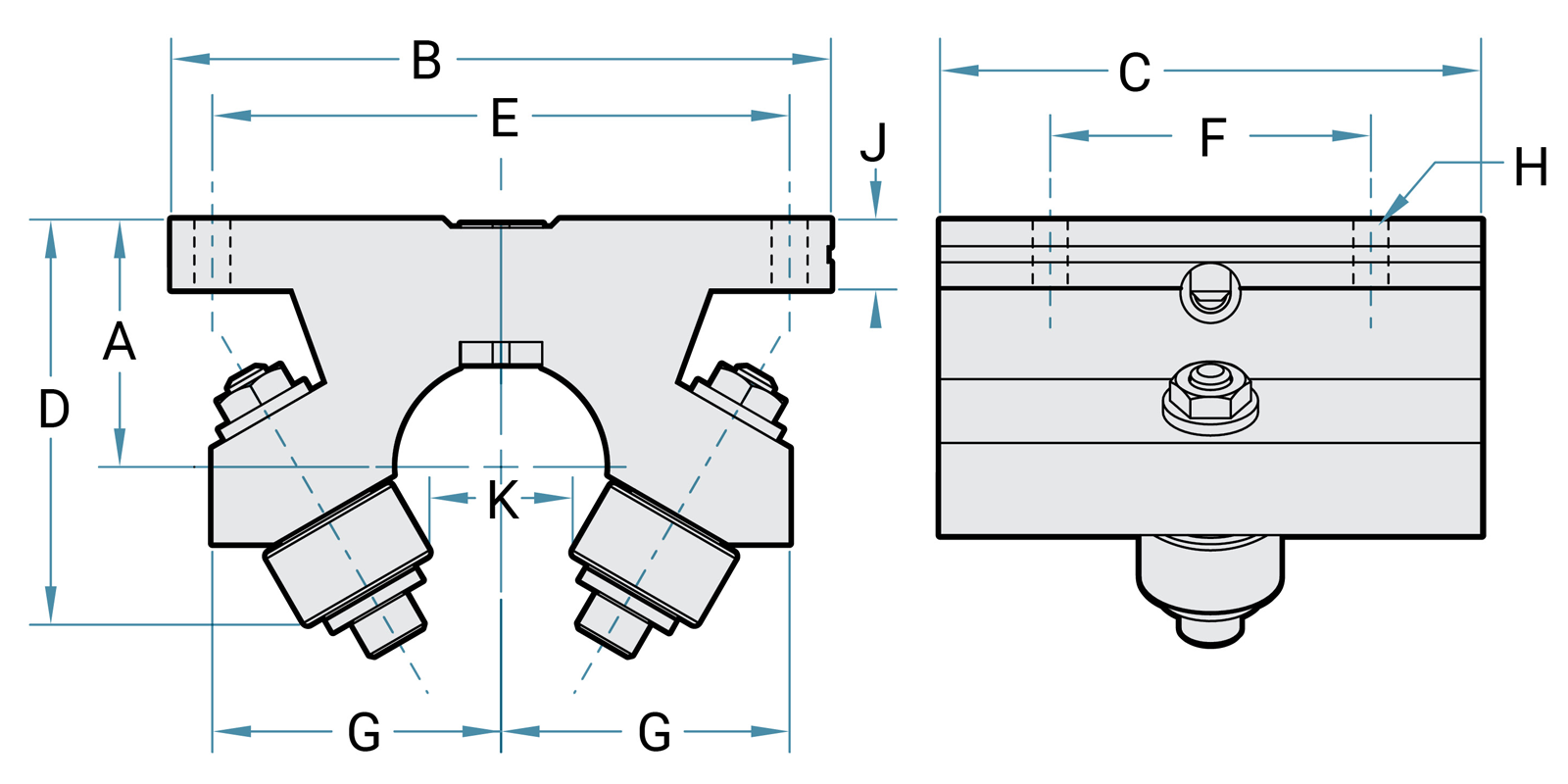

Double Roller Pillow Block DPB-OPN
Double the capacity of the Single Roller Pillow Block. The double Roller Pillow Blocks offer twice the dynamic load rating in a similar mounting footprint. The Double Roller Pillow Blocks are used when longer travel life or an increase in load capacity is required.
Dimensions and Load Ratings Inch Shafting
| Part No. | Shaft Diameter in. |
DYN. Load Rating lb. |
Weight lb. |
A +-0.003 |
B in. |
C in. |
D in. |
E +-0.005 |
F +-0.005 |
G in. |
H | J in. |
K in. |
L in. |
|
|---|---|---|---|---|---|---|---|---|---|---|---|---|---|---|---|
| Bolt | Hole | ||||||||||||||
| DPB-08-OPN | 1/2 | 800 | 0.50 | 0.687 | 2.000 | 2.000 | 1.156 | 1.688 | 1.625 | 1.000 | #6 | 0.1563 | 0.240 | 0.313 | 0.562 |
| DPB-10-OPN | 5/8 | 1000 | 0.70 | 0.875 | 2.500 | 2.500 | 1.406 | 2.125 | 2.000 | 1.063 | #8 | 0.1875 | 0.270 | 0.375 | 0.526 |
| DPB-12-OPN | 3/4 | 1200 | 0.80 | 0.937 | 2.750 | 2.625 | 1.563 | 2.375 | 1.250 | 1.063 | #8 | 0.1875 | 0.300 | 0.438 | 0.562 |
| DPB-16-OPN | 1 | 1910 | 1.20 | 1.187 | 3.254 | 2.625 | 2.000 | 2.875 | 1.750 | 1.375 | #10 | 0.2188 | 0.360 | 0.688 | 0.720 |
| DPB-20-OPN | 1-1/4 | 2800 | 2.30 | 1.500 | 4.000 | 3.375 | 2.563 | 3.500 | 2.000 | 1.750 | #10 | 0.2188 | 0.424 | 0.813 | 0.937 |
| DPB-24-OPN | 1-1/2 | 3320 | 3.00 | 1.750 | 4.750 | 3.750 | 2.875 | 4.125 | 2.500 | 1.875 | 1/4 | 0.2813 | 0.474 | 1.063 | 0.937 |
| DPB-32-OPN | 2 | 4800 | 5.50 | 2.125 | 6.000 | 4.750 | 3.500 | 5.250 | 3.250 | 2.500 | 3/8 | 0.4063 | 0.603 | 1.375 | 1.187 |
| DPB-48-OPN | 3 | 12520 | 20.00 | 3.500 | 8.375 | 7.250 | 5.500 | 7.000 | 5.875 | 3.875 | 5/8 | 0.6563 | 1.000 | 2.125 | 2.080 |
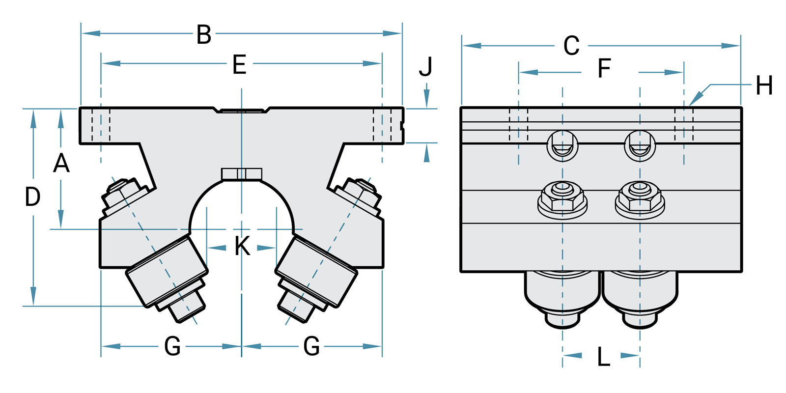
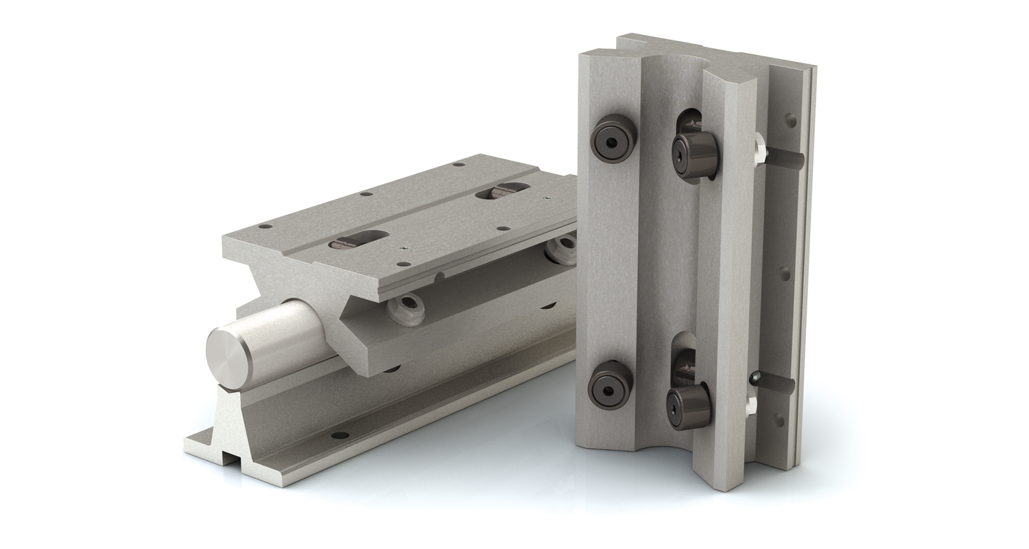
Twin Roller Pillow Block TWN-OPN
The Twin Roller Pillow Block load rating is the same as the double and is a good choice when using only one Roller Pillow Block per shaft. The twin model also offers an additional pair of mounting holes.
Dimensions and Load Ratings Inch Shafting
| Part No. | Shaft Diameter in. |
DYN. Load Rating lb. |
Weight lb. |
A +-0.003 |
B in. |
C in. |
D in. |
E +-0.005 |
F +-0.005 |
G in. |
H | J in. |
K in. |
L in. |
|
|---|---|---|---|---|---|---|---|---|---|---|---|---|---|---|---|
| Bolt | Hole | ||||||||||||||
| TWN-08-OPN | 1/2 | 800 | 0.80 | 0.687 | 2.000 | 3.50 | 1.156 | 1.688 | 2.50 | 1.000 | #6 | 0.1563 | 0.240 | 0.313 | 1.500 |
| TWN-10-OPN | 5/8 | 1000 | 1.00 | 0.875 | 2.500 | 4.00 | 1.406 | 2.125 | 3.00 | 1.063 | #8 | 0.1875 | 0.270 | 0.375 | 2.125 |
| TWN-12-OPN | 3/4 | 1200 | 1.20 | 0.937 | 2.750 | 4.50 | 1.563 | 2.375 | 3.50 | 1.063 | #8 | 0.1875 | 0.300 | 0.438 | 2.500 |
| TWN-16-OPN | 1 | 1910 | 2.30 | 1.187 | 3.254 | 6.00 | 2.000 | 2.875 | 4.50 | 1.375 | #10 | 0.2188 | 0.360 | 0.688 | 3.750 |
| TWN-20-OPN | 1-1/4 | 2800 | 4.40 | 1.500 | 4.000 | 7.50 | 2.563 | 3.500 | 5.50 | 1.750 | #10 | 0.2188 | 0.424 | 0.813 | 4.625 |
| TWN-24-OPN | 1-1/2 | 3320 | 6.50 | 1.750 | 4.750 | 9.00 | 2.875 | 4.125 | 6.50 | 1.875 | 1/4 | 0.2813 | 0.474 | 1.063 | 5.500 |
| TWN-32-OPN | 2 | 4800 | 12.40 | 2.125 | 6.000 | 12.00 | 3.500 | 5.250 | 10.50 | 2.500 | 3/8 | 0.4063 | 0.600 | 1.375 | 8.250 |
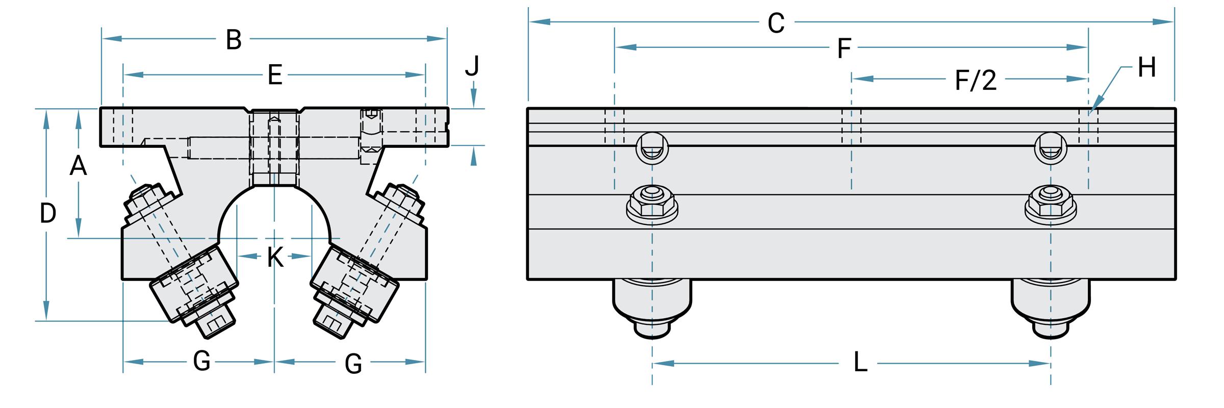
Roller Pillow Block Accessories
Top Grease Option
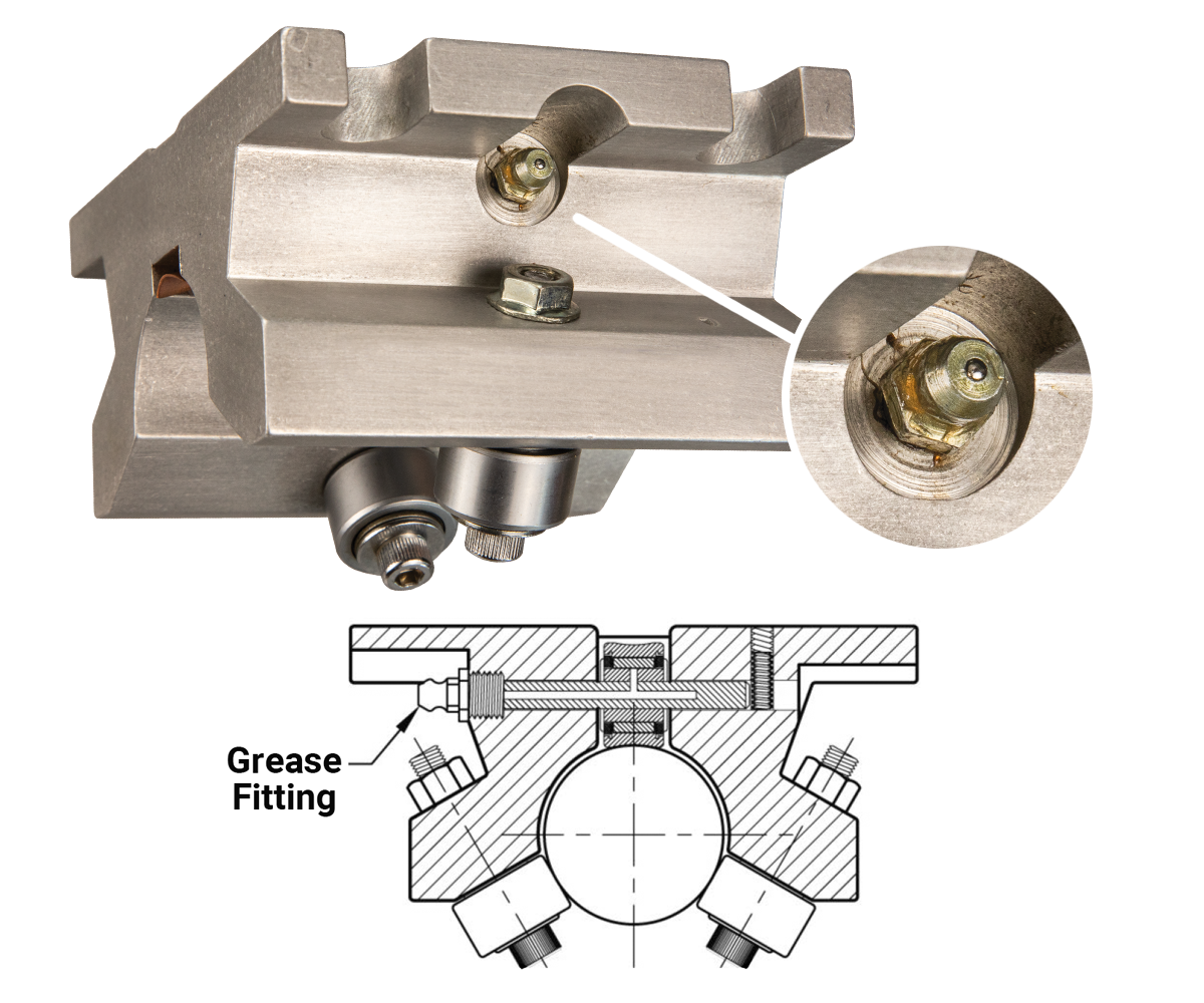
Roller Pillow Block rollers are lubricated and sealed. In some applications it is desired to re-grease the main support roller. The top grease option can help achieve full bearing life in applications that reduce or contaminate the grease of the roller. Such conditions may exist in applications where solvents or contaminants leach out the grease through the vents in the seals, or where contaminants are so fine or extreme they must be purged out of the roller with fresh grease. The top grease option is also recommended when high speeds or high temperatures are present. The top grease option is available on pillow blocks that are 1-1/4" or larger.
To order, add the suffix, “TG” after the pillow block model number.
Note: Shock, vibration, and moments may affect the life of the pillow block.
Floating Option
The only product on the market that addresses the non-parallel shafting problem is a Roller Pillow Block with the floating option. Also useful when trying to align long shafts, floating Roller Pillow Blocks should be used on one shaft with the standard pillow block on the other. Special grease is included for the grooves on top of each floating pillow block.
During installation do not over-tighten the mounting bushings as this will cause them to bind.
To order, add the prefix, “F-“ to the single, double, or twin Roller Pillow Block number.
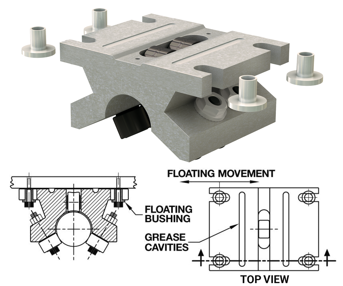
| Pillow Block Size | Floating Movement |
|---|---|
| 8 | 0.0625" |
| 10 | 0.0625" |
| 12 | 0.0625" |
| 16 | 0.0938" |
| 20 | 0.1250" |
| 24 | 0.1250" |
| 32 | 0.1563" |
| 48 | 0.1875" |
| 64 | 0.1875" |
Scraper Option
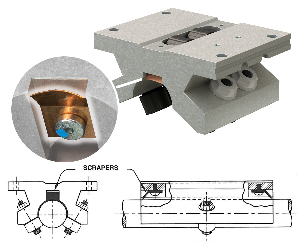
Reduce the amount of dirt accumulation that lands on the top of the Roller Pillow Block shaft with the scraper option. Available only on specially machined pillow blocks, the scraper is mounted to each end of the bearing assembly to clean the shaft in either direction. Made from spring-tempered beryllium copper that conforms to the shaft diameter, the scraper will perform successfully after a short break in period. Scraper model is not available as a retrofit.
To order this option, add the suffix “-S” after the pillow block model number.
Linear Carriage Lock
The linear carriage lock is a positive locking device for linear slides, carriages, and bearings.
The Locks are:
- Self-centering
- Corrosion resistant
- Strong holding
- Contaminant resistant
- Easily mounted
- Maintenance-free
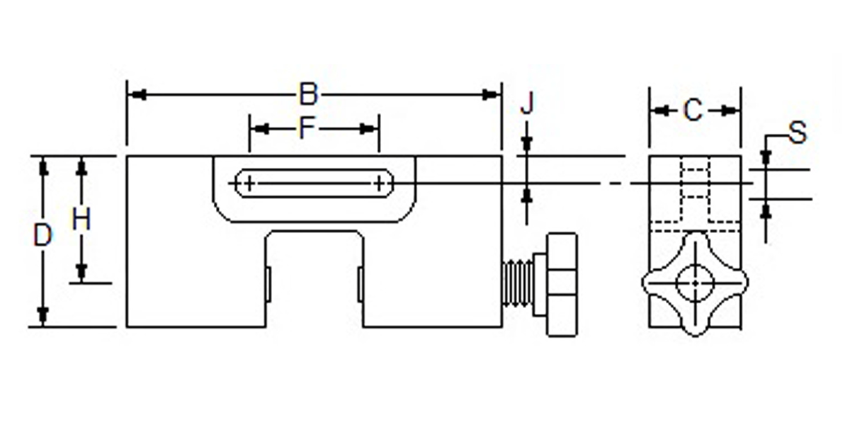
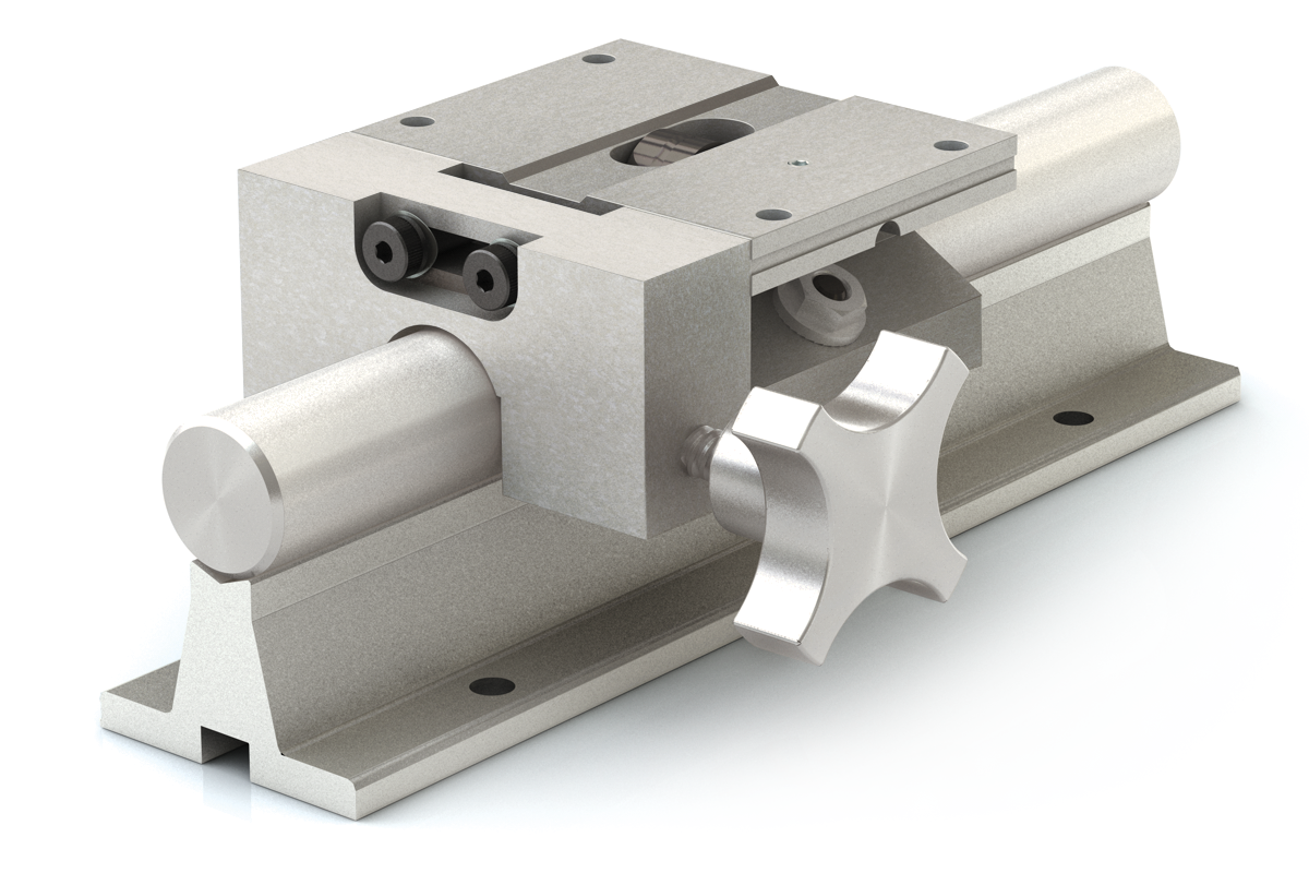
| Part Nuber | Shaft Diameter in. |
D in. |
B in. |
C in. |
J in. |
F in. |
H in. |
S in. |
|---|---|---|---|---|---|---|---|---|
| LCL-08 | 1/2 | 0.92 | 2.00 | 1 | 0.22 | 0.81 | 0.69 | 0.26 |
| LCL-12 | 3/4 | 1.25 | 2.75 | 1 | 0.22 | 0.81 | 0.94 | 0.26 |
| LCL-16 | 1 | 1.60 | 3.25 | 1 | 0.27 | 0.81 | 1.18 | 0.26 |
| LCL-24 | 1-1/2 | 2.29 | 4.75 | 1 | 0.40 | 0.81 | 1.75 | 0.26 |
| LCL-32 | 2 | 2.85 | 6.00 | 1 | 0.50 | 1.25 | 2.13 | 0.50 |
Note: When ordering with a Roller Pillow Block that it will be mounted to, just add "-LCL" to the Roller Pillow Block part number (EX: SPB-12-OPN-LCL)
Pillow Block Rebuild Kits
The Roller Pillow Block rebuild kit contains all the parts required for a complete unit rebuild:
- One fixed side roller
- One eccentric side roller
- One top support roller
- One top roller axle
- One set screw
| Part Nuber | Shaft Diameter |
|---|---|
| FUBK08 | 1/2 |
| FUBK10 | 5/8" |
| FUBK12 | 3/4" |
| FUBK16 | 1" |
| FUBK20 | 1-1/4" |
| FUBK24 | 1-1/2" |
| FUBK32 | 2" |
| FUBK48 | 3" |
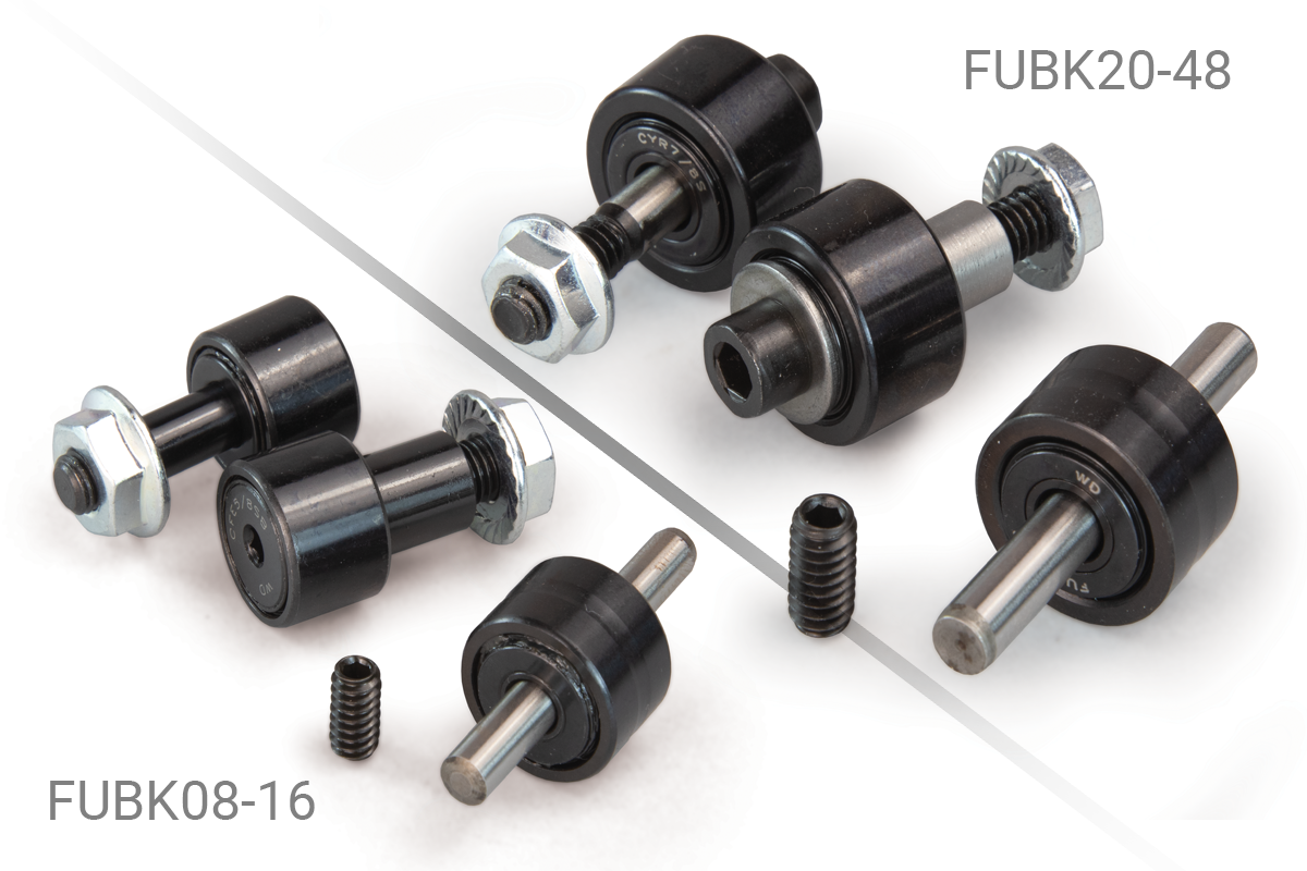
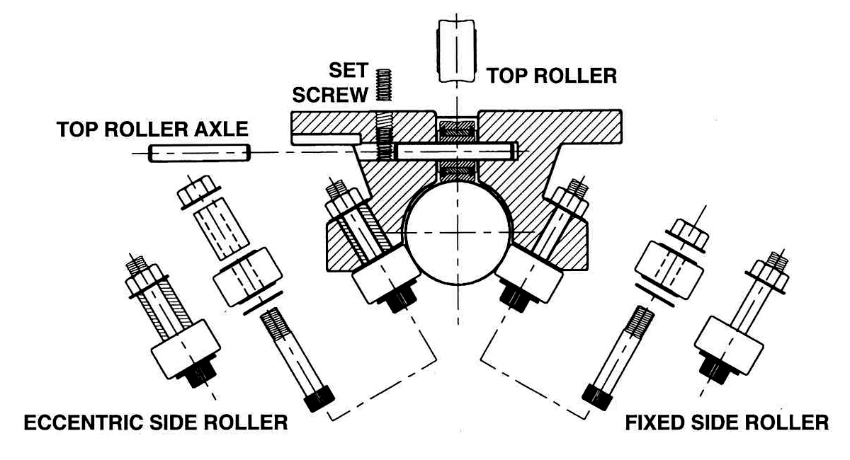
To rebuild a Double or Twin Roller Pillow Block, please order 2 kits.
All parts of a Roller Pillow Block should be replaced before re-installation.
Shaft & Rail Systems
Shaft & Rail Systems
PBC Linear offers shaft and rail systems composed of world-class linear motion components in six standard configurations in four different sizes.
These systems also come with the option of carriage plates with or without mounted pillow blocks.
Support Block System
Support block systems are manufactured with Roller Pillow Block(s), 60 Plus® precision case hardened and ground shaft, and two steel support blocks.
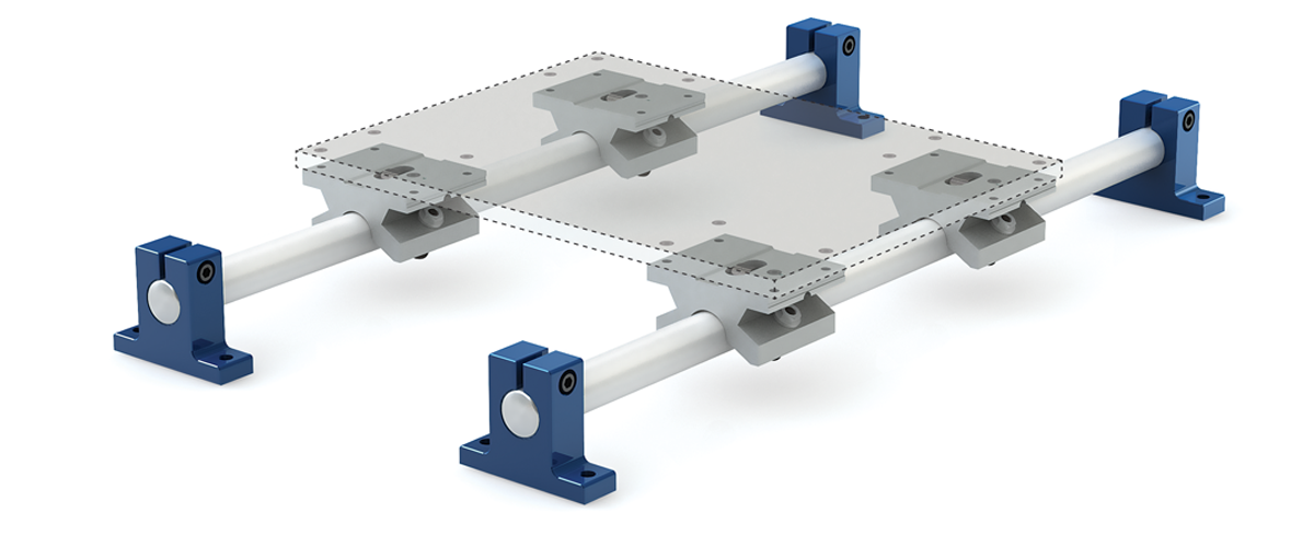
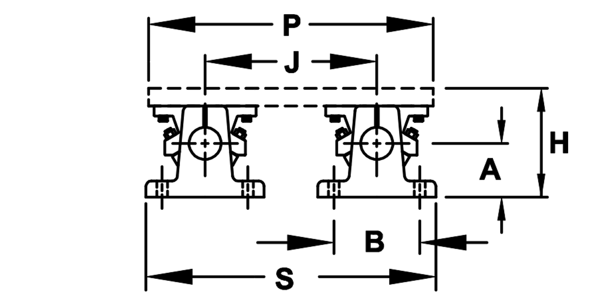
Support Block System
End View
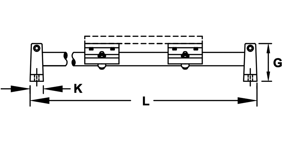
Single Pillow Block System
Part Number Prefix: S1S
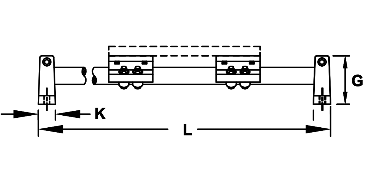
Double Pillow Block System
Part Number Prefix: S1D
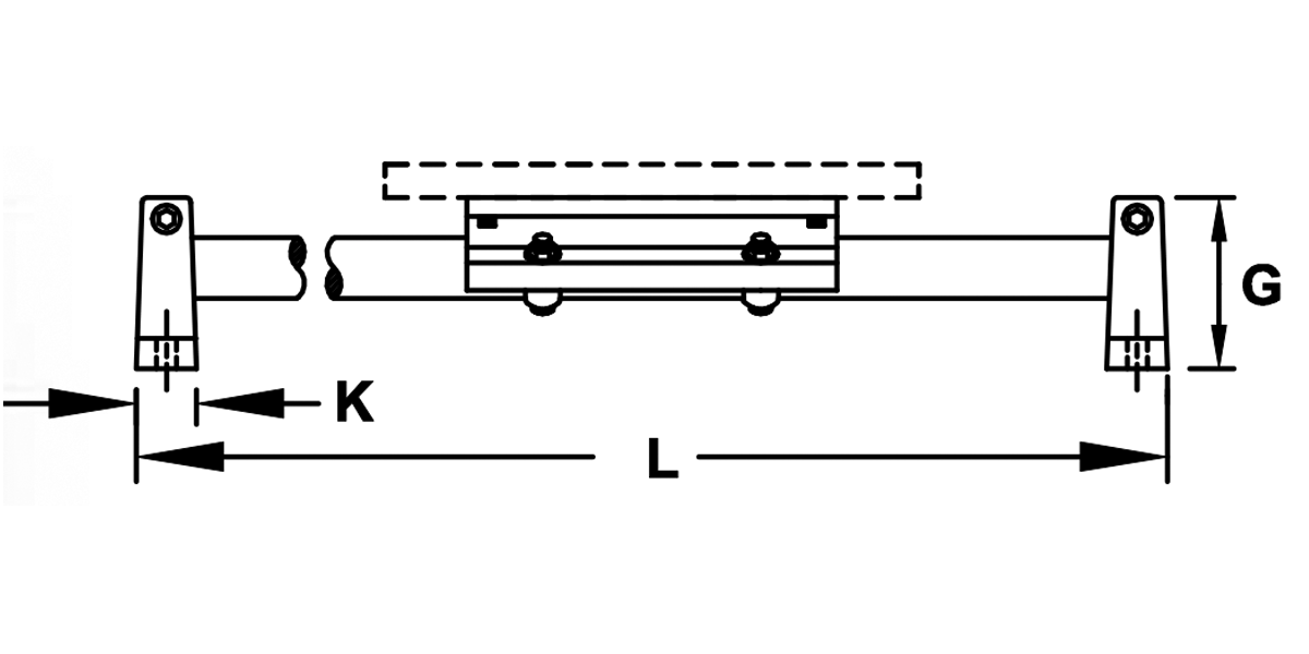
Twin Pillow Block System
Part Number Prefix: S1T
Technical Information
| Type Roller Pillow Block | Part Number | Shaft Diameter in. |
Total Basic Dynamic Rating lb. |
Number Roller Pillow Blocks | Number Support Blocks | Number Hardened Shafts | A in. |
B in. |
G in. |
H in. |
J in. |
K in. |
P in. |
S in. |
|---|---|---|---|---|---|---|---|---|---|---|---|---|---|---|
| Single | S1S08 | 0.50 | 800 | 2 | 2 | 1 | 1.00 | 2.00 | 1.63 | 2.187 | 3.25 | 0.63 | 5.50 | 5.25 |
| Double | S1D08 | 0.50 | 1600 | 2 | 2 | 1 | 1.00 | 2.00 | 1.63 | 2.187 | 3.25 | 0.63 | 5.50 | 5.25 |
| Twin | S1T08 | 0.50 | 800 | 1 | 2 | 1 | 1.00 | 2.00 | 1.63 | 2.187 | 3.25 | 0.63 | 5.50 | 5.25 |
| Single | S1S12 | 0.75 | 1200 | 2 | 2 | 1 | 1.25 | 2.75 | 2.13 | 2.937 | 4.50 | 0.75 | 7.50 | 7.25 |
| Double | S1D12 | 0.75 | 2400 | 2 | 2 | 1 | 1.25 | 2.75 | 2.13 | 2.937 | 4.50 | 0.75 | 7.50 | 7.25 |
| Twin | S1T12 | 0.75 | 1200 | 1 | 2 | 1 | 1.25 | 2.75 | 2.13 | 2.937 | 4.50 | 0.75 | 7.50 | 7.25 |
| Single | S1S16 | 1.00 | 1910 | 2 | 2 | 1 | 1.50 | 3.25 | 2.63 | 3.437 | 5.50 | 1.00 | 9.00 | 8.75 |
| Double | S1D16 | 1.00 | 3820 | 2 | 2 | 1 | 1.50 | 3.25 | 2.63 | 3.437 | 5.50 | 1.00 | 9.00 | 8.75 |
| Twin | S1T16 | 1.00 | 1910 | 1 | 2 | 1 | 1.50 | 3.25 | 2.63 | 3.437 | 5.50 | 1.00 | 9.00 | 8.75 |
| Single | S1S24 | 1.50 | 3320 | 2 | 2 | 1 | 2.00 | 4.75 | 3.50 | 5.000 | 8.00 | 1.25 | 13.00 | 12.75 |
| Double | S1D24 | 1.50 | 6640 | 2 | 2 | 1 | 2.00 | 4.75 | 3.50 | 5.000 | 8.00 | 1.25 | 13.00 | 12.75 |
| Twin | S1T24 | 1.50 | 3320 | 1 | 2 | 1 | 2.00 | 4.75 | 3.50 | 5.000 | 8.00 | 1.25 | 13.00 | 12.75 |
Support Rail Systems
Support rail systems are manufactured with Roller Pillow Blocks and 60 Plus® precision case hardened and ground shaft that is mounted on a continuous aluminum support rail. To prevent the carriage from sliding off the shaft, end stops can be purchased.
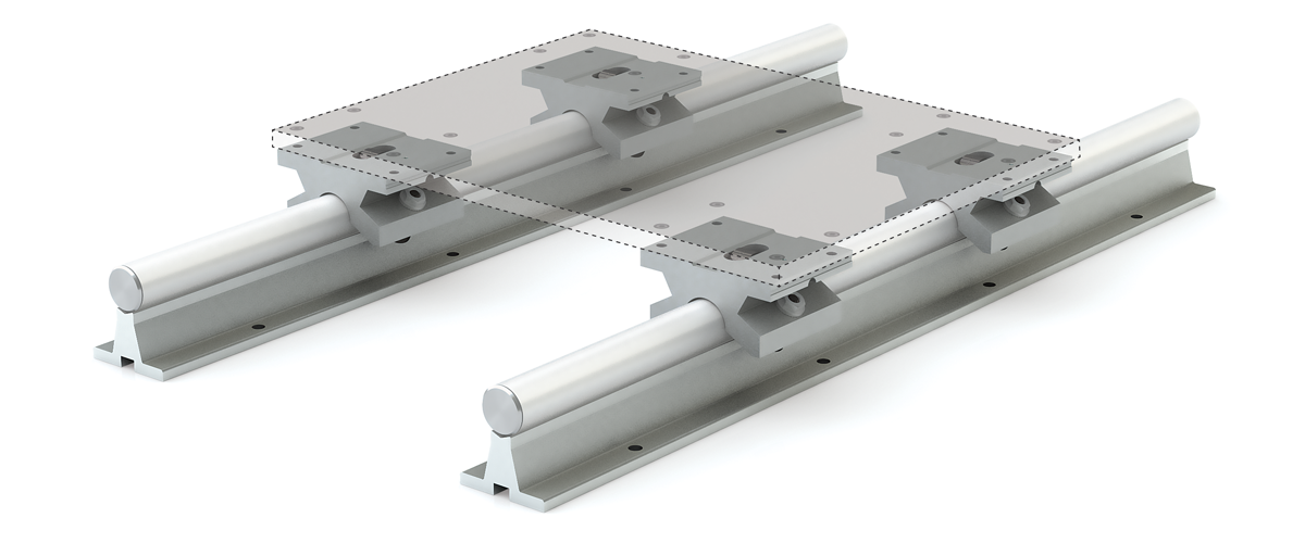
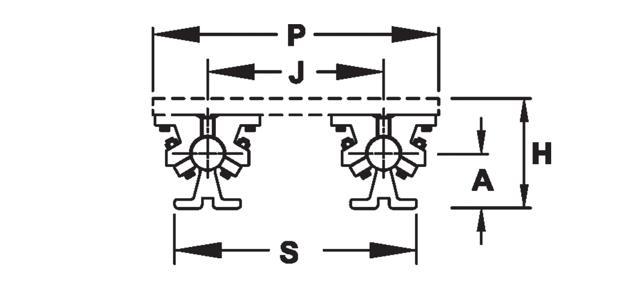
End View
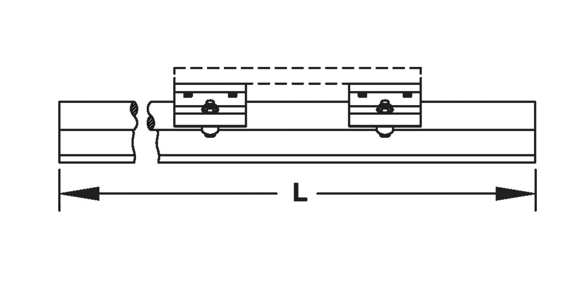
Single Pillow Block System
Part Number Prefix: S2S
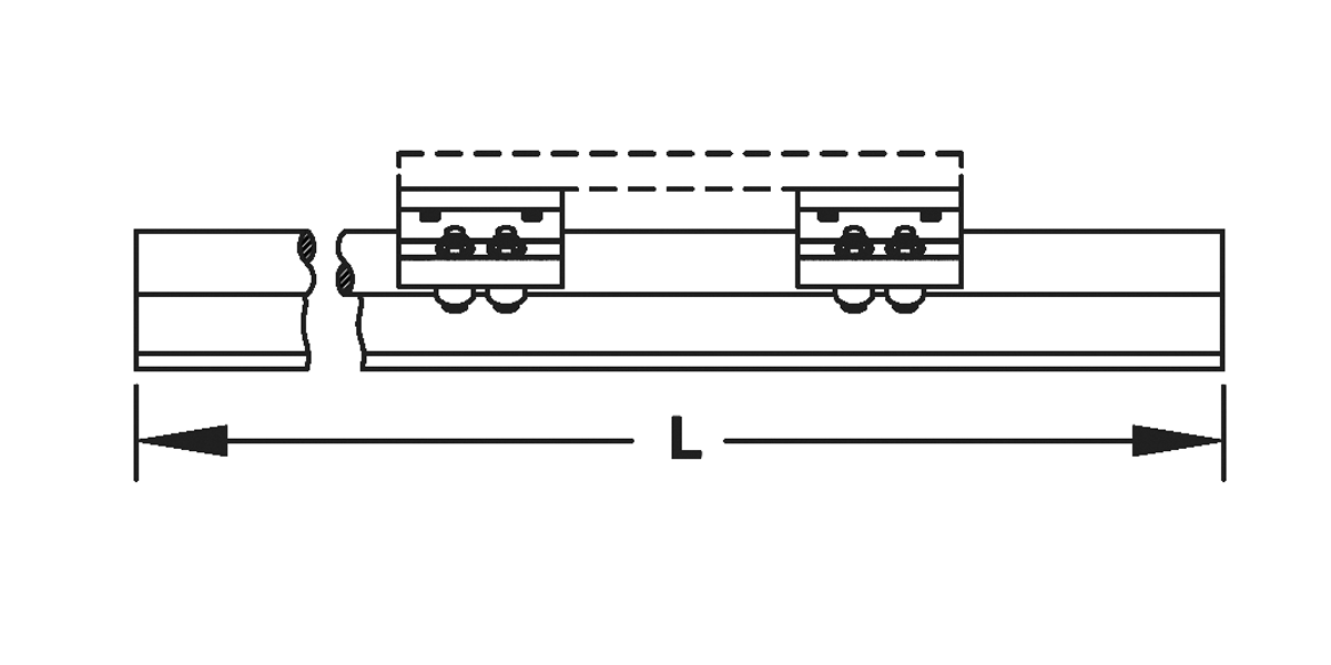
Double Pillow Block System
Part Number Prefix: S2D
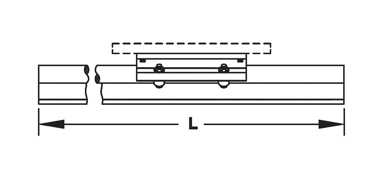
Twin Pillow Block System
Part Number Prefix: S2T
Technical Information
| Type Roller Pillow Block | Part Number | Shaft Diameter in. |
Total Basic Dynamic Rating lb. |
Number Roller Pillow Blocks | Number Support Blocks | Number Hardened Shafts | A in. |
H in. |
J in. |
P in. |
S in. |
|---|---|---|---|---|---|---|---|---|---|---|---|
| Single | S2S08 | 1/2 | 800 | 2 | 1 | 1 | 1.125 | 2.187 | 3.25 | 5.5 | 4.75 |
| Double | S2D08 | 1/2 | 1600 | 2 | 1 | 1 | 1.125 | 2.187 | 3.25 | 5.5 | 4.75 |
| Twin | S2T08 | 1/2 | 800 | 1 | 1 | 1 | 1.125 | 2.187 | 3.25 | 5.5 | 4.75 |
| Single | S2S12 | 3/4 | 1200 | 2 | 1 | 1 | 1.500 | 2.937 | 4.50 | 7.5 | 6.25 |
| Double | S2D12 | 3/4 | 2400 | 2 | 1 | 1 | 1.500 | 2.937 | 4.50 | 7.5 | 6.25 |
| Twin | S2T12 | 3/4 | 1200 | 1 | 1 | 1 | 1.500 | 2.937 | 4.50 | 7.5 | 6.25 |
| Single | S2S16 | 1 | 1910 | 2 | 1 | 1 | 1.750 | 3.437 | 5.50 | 9.0 | 7.63 |
| Double | S2D16 | 1 | 3820 | 2 | 1 | 1 | 1.750 | 3.437 | 5.50 | 9.0 | 7.63 |
| Twin | S2T16 | 1 | 1910 | 1 | 1 | 1 | 1.750 | 3.437 | 5.50 | 9.0 | 7.63 |
| Single | S2S24 | 1-1/2 | 3320 | 2 | 1 | 1 | 2.500 | 5.000 | 8.00 | 13.0 | 11.00 |
| Double | S2D24 | 1-1/2 | 6640 | 2 | 1 | 1 | 2.500 | 5.000 | 8.00 | 13.0 | 11.00 |
| Twin | S2T24 | 1-1/2 | 3320 | 1 | 1 | 1 | 2.500 | 5.000 | 8.00 | 13.0 | 11.00 |
Round Shafting
Simplicity 60 Plus® Shafting

PBC Linear® formulated a linear shaft designed specifically for optimal bearing performance – 60 Plus Shafting. Advanced process capabilities maintain the ideal surface finish for linear bearings resulting in the longest life and highest performing shaft-to-bearing combination available:
- Optimized surface finish
- Faster break-in and better Frelon® transfer for plain bearings
- Longest life possible, less down time, and maintenance
- Straight to within 0.001" to 0.002" per foot cumulative, except on 3/8" diameter and smaller
Inch Shaft Part • Numbering Chart
| Class | Diameter | Material | Length | Type | ||
| NIL | 03 | SS | - | 010.000 | - | CM |
ClassNIL = Inch Class L Shaft (Steel) NIPDL = Inch Class L Predrill (Steel) CC = Feather Inch (Aluminum) CCPDL = Feather Inch Predrill (Aluminum) SR = Inch Support Rail (Aluminum) SRA = Inch Support Rail Assembly (Aluminum) CCR = Feather Rail Assembly (Aluminum) LSRA = Inch Low Support Rail Assembly (Steel) LSR = Inch Low Support Rail (Steel) LSG = Inch Low Support Rail Assembly (Steel) NIS = Inch Class S Shaft (Steel) NIN = Inch Class N Shaft (Steel) Diameter03 = 3/16" 04 = 1/4" 06 = 3/8" 08 = 1/2" 10 = 5/8" 12 = 3/4" 16 = 1" 20 = 1 1/4" 24 = 1 1/2" 32 = 2" 40 = 2 1/2" 48 = 3" 64 = 4" Shaft MaterialBLANK = 1060 CS SS = 440 SS SS420 = 420 SS SS316 = 316 SS* ** CP = Chrome plate** AR = Armoloy** * 300 Series available in most diameters ** Available as special quotes Shaft LengthInch - 000.000 SpecialCM = Custom Machine SL = Specified Length |
Note: Chrome will have a guaranteed thickness of 0.0001" to 0.0005". Chrome thickness will be in addition to the catalog diameter of the shaft.
Online Configurator
Sample Part Numbers
CC16-015.000-SL
Feather inch, 1" diameter and 15" long
SRA24SS-012.000-SL
Support rail assembly 1.5" diameter 440 stainless steel and 12" long
Round Shafting Steel & Stainless Steel
Simplicity RC60 Steel Solid Shafting NI
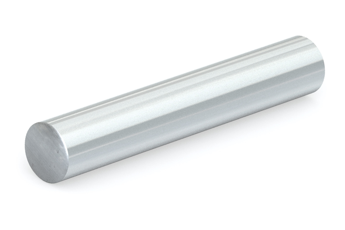
- RC 60 Plus case hardened steel shafting
- Optimized for Simplicity bearings and linear ball bearings
- Available cut-to-length or full lengths
- Length tolerance:
- 3/16" – 1-1/4" shaft = +/- 0.030"
- 1-3/8" – 2" shaft = +/- 0.060"
- 2-1/2" – 4" shaft = +/- 0.125"
| Part No. | Nominal Dia. in. |
Dia. Tolerance Class L* in. |
Dia. Tolerance Class S* in. |
Dia. Tolerance Class N* in. |
Max Length in. |
Min Hardness Depth in. |
Weight per In. lb. |
|||
|---|---|---|---|---|---|---|---|---|---|---|
| MIN | MAX** | MIN | MAX** | MIN | MAX** | |||||
| NI_*03-xxx.xxx | 3/16" | 0.1865 | 0.1870 | – | – | – | – | 252 | 0.027 | 0.008 |
| NI_*04-xxx.xxx | 1/4" | 0.2490 | 0.2495 | 0.2485*** | 0.2490*** | 0.2498*** | 0.2500*** | 252 | 0.027 | 0.014 |
| NI_*06-xxx.xxx | 3/8" | 0.3740 | 0.3745 | 0.3735*** | 0.3740*** | 0.3748*** | 0.3750*** | 252 | 0.027 | 0.031 |
| NI_*08-xxx.xxx | 1/2" | 0.4990 | 0.4995 | 0.4985 | 0.4990 | 0.4998 | 0.5000 | 180 | 0.040 | 0.055 |
| NI_*10-xxx.xxx | 5/8" | 0.6240 | 0.6245 | 0.6235 | 0.6240 | 0.6248 | 0.6250 | 180 | 0.040 | 0.086 |
| NI_*12-xxx.xxx | 3/4" | 0.7490 | 0.7495 | 0.7485 | 0.7490 | 0.7498 | 0.7500 | 180 | 0.060 | 0.125 |
| NI_*14-xxx.xxx | 7/8” | 0.8740 | 0.8745 | -- | -- | 0.8748 | 0.8750 | 180 | 0.060 | 0.170 |
| NI_*16-xxx.xxx | 1" | 0.9990 | 0.9995 | 0.9985 | 0.9990 | 0.9998 | 1.0000 | 180 | 0.080 | 0.222 |
| NI_*18-xxx.xxx | 1-1/8” | 1.1240 | 1.1245 | -- | -- | 1.1248 | 1.1250 | 180 | 0.080 | 0.281 |
| NI_*20-xxx.xxx | 1-1/4" | 1.2490 | 1.2495 | 1.2485 | 1.2490 | 1.2498 | 1.2500 | 180 | 0.080 | 0.348 |
| NI_*22-xxx.xxx | 1-3/8” | 1.3740 | 1.3745 | -- | -- | 1.3747 | 1.3750 | 180 | 0.080 | 0.420 |
| NI_*24-xxx.xxx | 1-1/2" | 1.4989 | 1.4994 | 1.4984 | 1.4989 | 1.4997 | 1.5000 | 180 | 0.080 | 0.500 |
| NI_*28-xxx.xxx | 1-3/4” | 1.7490 | 1.7495 | -- | -- | 1.7497 | 1.7500 | 180 | 0.100 | 0.681 |
| NI_*32-xxx.xxx | 2" | 1.9987 | 1.9994 | 1.9980 | 1.9987 | 1.9997 | 2.0000 | 180 | 0.100 | 0.890 |
| NI_*40-xxx.xxx | 2-1/2" | 2.4985 | 2.4993 | 2.4977 | 2.4985 | 2.4996 | 2.5000 | 180 | 0.100 | 1.391 |
| NI_*48-xxx.xxx | 3" | 2.9983 | 2.9992 | 2.9974 | 2.9983 | 2.9996 | 3.0000 | 180 | 0.100 | 2.003 |
| NI_*64-xxx.xxx | 4" | 3.9976 | 3.9988 | – | – | – | – | 140 | 0.100 | 3.560 |
*Third letter of Part No. reflects the shaft class (NIL for Class L, NIS for Class S, and NIN for Class N)
**MAX length subject to change.
***1/4" and 3/8" shafting are available in class S and N for volume requests only.
Notes:
(1) Specify length in part number using inches.
(2) Example: for 1/2"class T shafting total length 15" = NIL08-015.000
(3) Surface finish bearing recommended 8–10 Ra.
440 & 420 Stainless Steel Solid Shafting NI_SS & NI_SS420
- 440 & 420 stainless steel RC 50 Plus™ hardness
- Optimized for Simplicity bearings and linear ball bearings
- Available cut-to-length or full lengths
- Length tolerance:
- 3/16" – 1-1/4" shaft = +/- 0.030"
- 1-3/8" – 2" shaft = +/- 0.060"
- 2-1/2" – 4" shaft = +/- 0.125"
| Part No. | Nominal Dia. in. |
Dia. Tolerance Class L in. |
Dia. Tolerance Class S* in. |
Max Length in. |
Min Hardness Depth in. |
Weight per in. lb. |
|||
|---|---|---|---|---|---|---|---|---|---|
| 440 SS | 420 SS | Min. | Max. | Min. | Max.** | ||||
| NI_*03SS-xxx.xxx | NI_* 03SS420-xxx.xxx | 3/16" | 0.1865 | 0.1870 | N/A | N/A | 252 | 0.027 | 0.008 |
| NI_*04SS-xxx.xxx | NI_* 04SS420-xxx.xxx | 1/4" | 0.2490 | 0.2495 | 0.2485*** | 0.2490*** | 252 | 0.027 | 0.014 |
| NI_*06SS-xxx.xxx | NI_* 06SS420-xxx.xxx | 3/8" | 0.3740 | 0.3745 | 0.3735*** | 0.3740*** | 252 | 0.027 | 0.031 |
| NI_*08SS-xxx.xxx | NI_* 08SS420-xxx.xxx | 1/2" | 0.4990 | 0.4995 | 0.4985 | 0.4990 | 154 | 0.040 | 0.055 |
| NI_*10SS-xxx.xxx | NI_* 10SS420-xxx.xxx | 5/8" | 0.6240 | 0.6245 | 0.6235 | 0.6240 | 154 | 0.040 | 0.087 |
| NI_*12SS-xxx.xxx | NI_* 12SS420-xxx.xxx | 3/4" | 0.7490 | 0.7495 | 0.7485 | 0.7490 | 154 | 0.060 | 0.125 |
| NI_*16SS-xxx.xxx | NI_* 16SS420-xxx.xxx | 1" | 0.9990 | 0.9995 | 0.9985 | 0.9990 | 176 | 0.080 | 0.222 |
| NI_*20SS-xxx.xxx | NI_* 20SS420-xxx.xxx | 1-1/4" | 1.2490 | 1.2495 | 1.2485 | 1.2490 | 154 | 0.080 | 0.348 |
| NI_*24SS-xxx.xxx | NI_* 24SS420-xxx.xxx | 1-1/2" | 1.4989 | 1.4994 | 1.4984 | 1.4989 | 154 | 0.080 | 0.498 |
| NI_*32SS-xxx.xxx | NI_* 32SS420-xxx.xxx | 2" | 1.9987 | 1.9994 | 1.9980 | 1.9987 | 154 | 0.100 | 0.886 |
*Third letter of Part No. reflects the shaft class (NIL for Class L, NIS for Class S, and NIN for Class N).
**MAX length subject to change.
***1/4" and 3/4" shafting are available in class S for volume requests only.
Shafting Steel, Stainless Steel
& Ceramic Coated
Pre-Drilled & Tapped
Steel NIPDL • 440 Stainless Steel NIPDLxxSS
420 Stainless Steel NIPDLxxSS420 • 316 Stainless Steel NIPDLxxSS316
| Steel | 440 Stainless Steel | 420 Stainless Steel | 316 Stainless Steel | Nominal Dia. in. |
Dia. Tolerance Class L |
Standard Hole Spacing |
Thread | Max Length in. |
Weight per Inch lb. |
||
|---|---|---|---|---|---|---|---|---|---|---|---|
| Min. | Max. | X | Y | ||||||||
| NIPDL08 | NIPDL08SS | NIPDL08SS420 | NIPDL08SS316 | 1/2" | 0.4990 | 0.4995 | 4 | 2 | 6-32 | 144 | 0.055 |
| NIPDL10 | NIPDL10SS | NIPDL10SS420 | NIPDL10SS316 | 5/8" | 0.6240 | 0.6245 | 4 | 2 | 8-32 | 144 | 0.086 |
| NIPDL12 | NIPDL12SS | NIPDL12SS420 | NIPDL12SS316 | 3/4" | 0.7490 | 0.7495 | 6 | 3 | 10-32 | 144 | 0.125 |
| NIPDL16 | NIPDL16SS | NIPDL16SS420 | NIPDL16SS316 | 1" | 0.9990 | 0.9995 | 6 | 3 | 1/4-20 | 144 | 0.222 |
| NIPDL20 | NIPDL20SS | NIPDL20SS420 | NIPDL20SS316 | 1-1/4" | 1.2490 | 1.2495 | 6 | 3 | 5/16-18 | 144 | 0.348 |
| NIPDL24 | NIPDL24SS | NIPDL24SS420 | NIPDL24SS316 | 1-1/2" | 1.4989 | 1.4994 | 8 | 4 | 3/8-16 | 132 | 0.500 |
| NIPDL32 | NIPDL32SS | NIPDL32SS420 | NIPDL32SS316 | 2" | 1.9987 | 1.9994 | 8 | 4 | 1/2-13 | 132 | 0.890 |
| NIPDL48 | * | * | * | 3" | 2.9983 | 2.9992 | 8 | 4 | 3/4-10 | 132 | 2.003 |
Part Numbers are complete when Length and Type are added.
Example: NIPDL16SS-024.000-SL is the complete Part Number for a 1 inch diameter 440 Stainless Steel shaft of 24 inches
*Special orders available on this option.
Notes:
(1) Specify length in part number using inches. Example: for 1/2" shafting at a length of 15" = NIPDL08-015.000
(2) Customer specifies 'y' dimension, if different than standard. Hole-to-hole tolerance = +/-0.015".
(3) Consult factory for chrome plated or 303 stainless steel shafting.
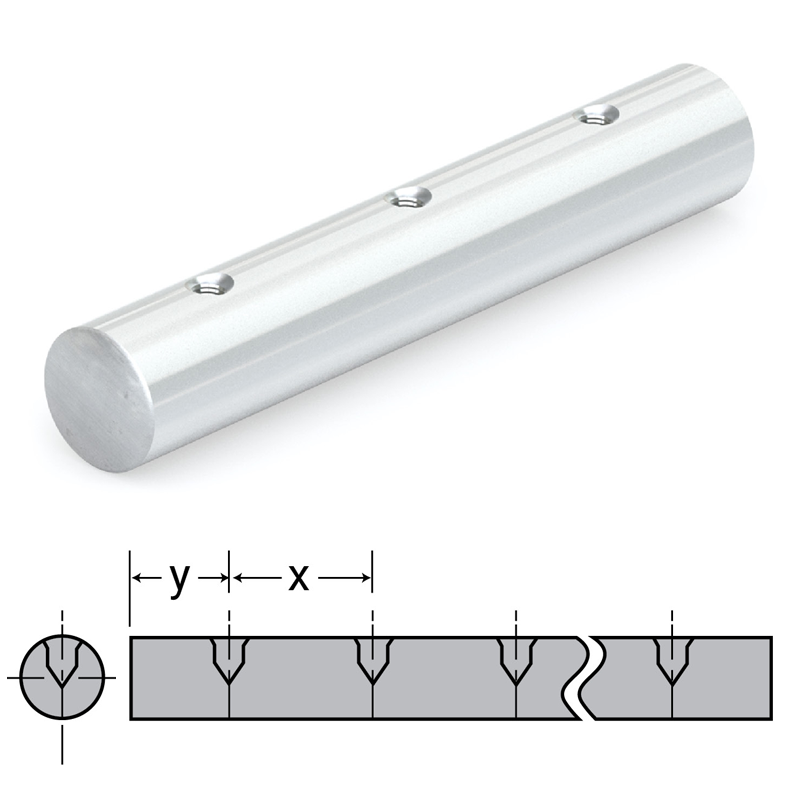
Ceramic Coated
- Aluminum alloy base material
- Optimized for FrelonGOLD® liners
- Interchanges with solid and pre-drilled shafting
- Non-magnetic and vibration resistant
- Weld splatter, paints, and contaminants will not stick
- Ceramic-like coating provides hardness up to RC70 and increased corrosion resistance
- NOT to be used with linear ball bearings (Does not apply to linear guide products – MR, UG, UGA, etc)
- NOT compatible with linear ball bearings or roller pillow block assemblies
- Length tolerance:
- 3/16" – 1-1/4" shaft = +/- 0.030"
- 1-3/8" – 2" shaft = +/- 0.060"
- 2-1/2" – 4" shaft = +/- 0.125"
Solid Shafting CC
| Part No. | Nominal Dia. in. |
Diameter Tolerance |
Max Length in. |
Weight lb./in. |
|
|---|---|---|---|---|---|
| MIN | MAX | ||||
| CC03-xxx.xxx | 3/16" | 0.1863 | 0.1871 | 138 | 0.003 |
| CC04-xxx.xxx | 1/4" | 0.2488 | 0.2496 | 138 | 0.005 |
| CC06-xxx.xxx | 3/8" | 0.3738 | 0.3746 | 138 | 0.010 |
| CC08-xxx.xxx | 1/2" | 0.4988 | 0.4996 | 138 | 0.019 |
| CC10-xxx.xxx | 5/8" | 0.6238 | 0.6246 | 138 | 0.030 |
| CC12-xxx.xxx | 3/4" | 0.7488 | 0.7496 | 138 | 0.043 |
| CC16-xxx.xxx | 1" | 0.9988 | 0.9996 | 138 | 0.077 |
| CC20-xxx.xxx | 1-1/4" | 1.2488 | 1.2496 | 138 | 0.120 |
| CC24-xxx.xxx | 1-1/2" | 1.4987 | 1.4995 | 138 | 0.173 |
| CC32-xxx.xxx | 2" | 1.9985 | 1.9995 | 138 | 0.308 |
Notes:
(1) Specify length in part number using inches. Example: for 1/2" shafting total length 36" long = CC08-036.000.
(2) Ends of cut-to-length shafting are not coated.
(3) Fully coated shafting is available on special request.
Pre-Drilled & Tapped CCPDL
| Part No. | Nominal Dia. in. |
Diameter Tolerance |
Standard Hole Spacing |
Thread | Max Length in. |
Weight lb./in. |
||
|---|---|---|---|---|---|---|---|---|
| MIN | MAX | X | Y | |||||
| CCPDL08-xxx.xxx | 1/2" | 0.4988 | 0.4996 | 4 | 2 | 6-32 | 138 | 0.019 |
| CCPDL10-xxx.xxx | 5/8" | 0.6238 | 0.6246 | 4 | 2 | 8-32 | 138 | 0.030 |
| CCPDL12-xxx.xxx | 3/4" | 0.7488 | 0.7496 | 6 | 3 | 10-32 | 138 | 0.043 |
| CCPDL16-xxx.xxx | 1" | 0.9988 | 0.9996 | 6 | 3 | 1/4-20 | 138 | 0.077 |
| CCPDL20-xxx.xxx | 1-1/4" | 1.2488 | 1.2496 | 6 | 3 | 5/16-18 | 138 | 0.120 |
| CCPDL24-xxx.xxx | 1-1/2" | 1.4987 | 1.4995 | 8 | 4 | 3/8-16 | 138 | 0.173 |
| CCPDL32-xxx.xxx | 2" | 1.9985 | 1.9995 | 8 | 4 | 1/2-13 | 138 | 0.308 |
Notes:
(1) Specify length in part number using inches. Example: for 1/2" shafting total length 36" long = CCPDL08-036.000.
(2) Ends of cut-to-length shafting are not coated.
(3) Fully coated shafting is available on special request.
(4) Counterbore 0.063" from top.
(5) Customer specifies 'y' dimension, if different than standard.

Shafting End Support Blocks
Aluminum End Support Block NSB
End support blocks can be used for end or intermittent shaft support. The aluminum end support block is lightweight and strong, and can be used with all shaft types. Ideally, they should be used where deflection between supports is not a problem.
- Available in inch sizes from 1/4"- 2"
- Instant bolt-down installation
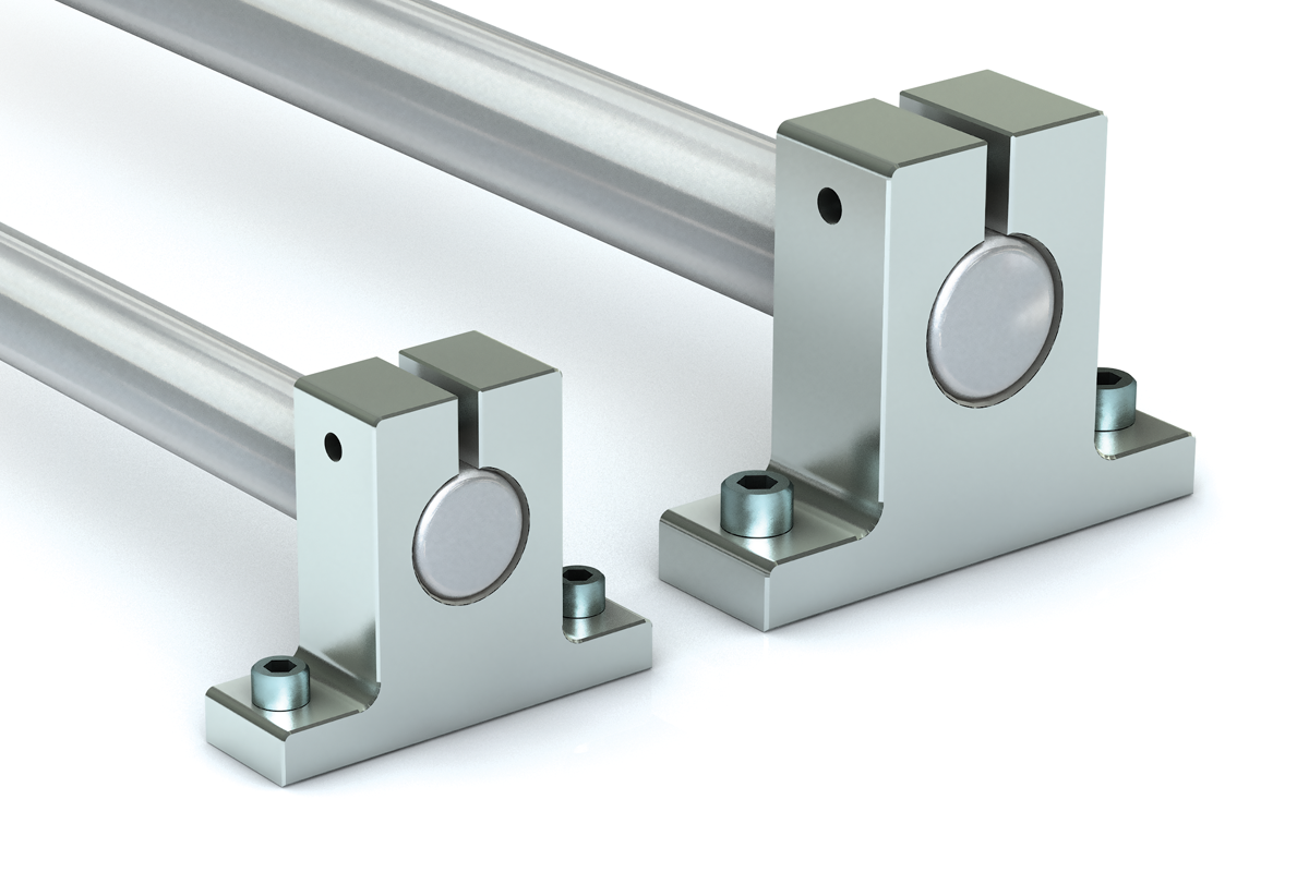
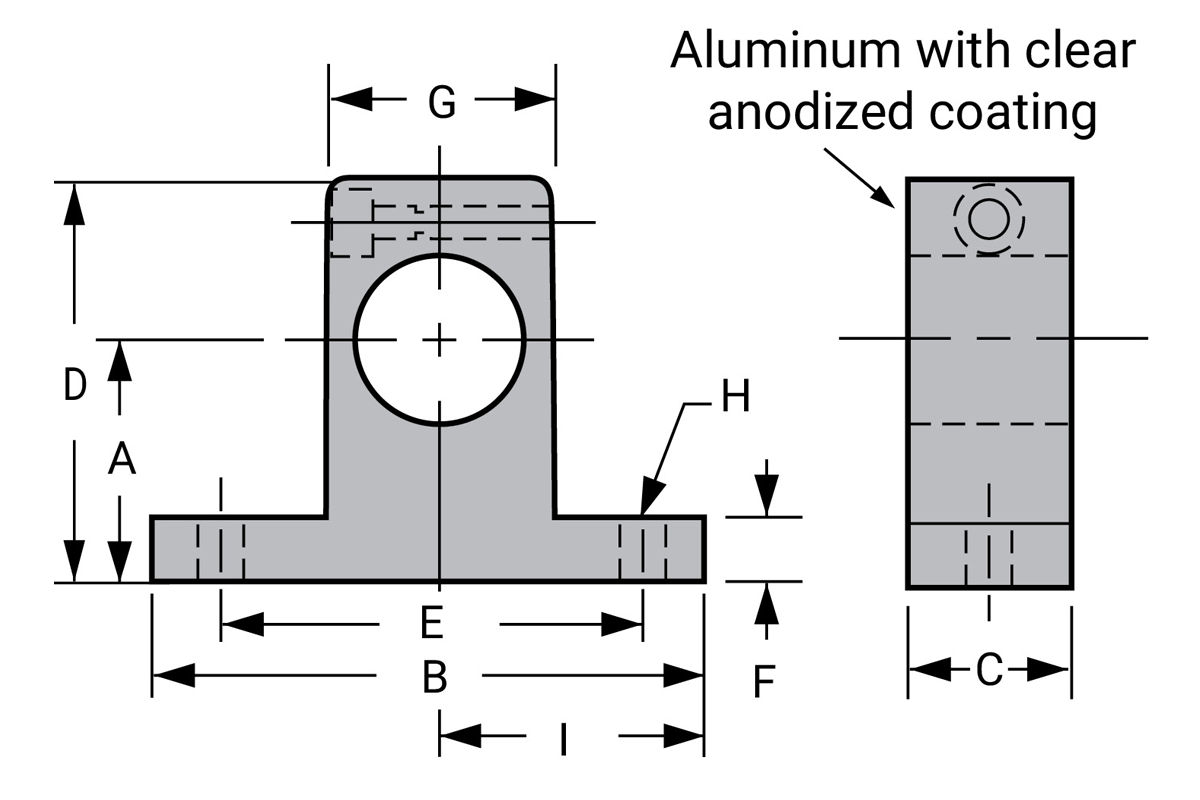
| Part No. | Nominal Dia. in. |
A +/- 0.001 |
B | C | D | E +/- 0.001 |
F | G | H | I +/- 0.001 |
Weight lb. |
|
|---|---|---|---|---|---|---|---|---|---|---|---|---|
| Bolt | Hole | |||||||||||
| NSB04 | 1/4" | 0.687 | 1.500 | 0.500 | 1.050 | 1.125 | 0.250 | 0.500 | #6 | 5/32" | 0.750 | 0.038 |
| NSB06 | 3/8" | 0.750 | 1.625 | 0.563 | 1.175 | 1.250 | 0.250 | 0.688 | #6 | 5/32” | 0.800 | 0.044 |
| NSB08 | 1/2" | 1.000 | 2.000 | 0.625 | 1.625 | 1.500 | 0.250 | 0.875 | #8 | 3/16" | 1.000 | 0.079 |
| NSB10 | 5/8" | 1.000 | 2.500 | 0.688 | 1.750 | 1.875 | 0.313 | 1.000 | #10 | 7/32" | 1.250 | 0.112 |
| NSB12 | 3/4" | 1.250 | 2.500 | 0.750 | 2.055 | 2.000 | 0.313 | 1.250 | #10 | 7/32” | 1.375 | 0.148 |
| NSB16 | 1" | 1.500 | 3.055 | 1.000 | 2.500 | 2.500 | 0.375 | 1.500 | 1/4" | 9/32" | 1.625 | 0.313 |
| NSB20 | 1-1/4" | 1.750 | 3.750 | 1.125 | 3.000 | 3.000 | 0.438 | 2.000 | 5/16" | 11/32" | 2.000 | 0.527 |
| NSB24 | 1-1/2" | 2.000 | 4.375 | 1.250 | 3.500 | 3.500 | 0.500 | 2.250 | 5/16" | 11/32" | 2.375 | 0.755 |
| NSB32 | 2" | 2.500 | 5.500 | 1.500 | 4.375 | 4.500 | 0.625 | 3.000 | 3/8" | 13/32" | 3.000 | 1.464 |
Steel End Support Block LSB
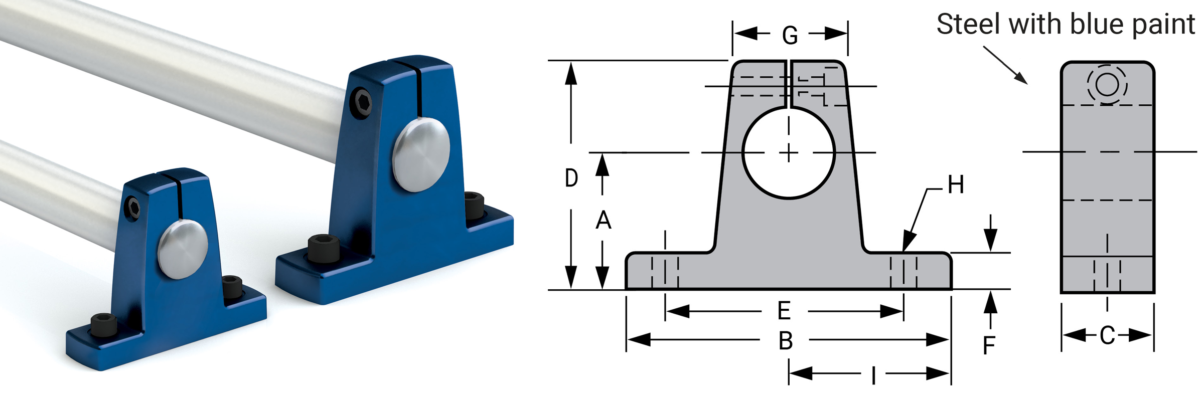
| Part No. | Retired Part No. |
Nom. Shaft Diameter |
A +/- 0.002 |
B | C | D | E +/- 0.005 |
F | G | H | I +/- 0.001 |
Weight lb. |
|
|---|---|---|---|---|---|---|---|---|---|---|---|---|---|
| Bolt | Hole | ||||||||||||
| LSB08 | SB-8 | 1/2 | 1.000 | 2.000 | 0.625 | 1.625 | 1.500 | 0.250 | 0.750 | #10 | 7/32 | 1.000 | 0.270 |
| LSB10 | SB-10 | 5/8 | 1.000 | 2.500 | 0.750 | 1.750 | 1.875 | 0.312 | 0.875 | #10 | 7/32 | 1.250 | 0.400 |
| LSB12 | SB-12 | 3/4 | 1.250 | 2.750 | 0.750 | 2.125 | 2.000 | 0.375 | 1.000 | 1/4 | 9/32 | 1.375 | 0.520 |
| LSB16 | SB-16 | 1 | 1.500 | 3.312 | 1.000 | 2.625 | 2.500 | 0.375 | 1.375 | 1/4 | 9/32 | 1.656 | 1.110 |
| LSB20 | SB-20 | 1-1/4 | 1.750 | 4.000 | 1.250 | 3.000 | 3.000 | 0.437 | 1.750 | 5/16 | 11/32 | 2.000 | 1.910 |
| LSB24 | SB-24 | 1-1/2 | 2.000 | 4.750 | 1.250 | 3.500 | 3.500 | 0.500 | 2.000 | 5/16 | 11/32 | 2.375 | 2.520 |
| LSB32 | SB-32 | 2 | 2.500 | 6.000 | 1.500 | 4.500 | 5.000 | 0.625 | 2.625 | 3/8 | 13/32 | 3.000 | 5.100 |
| LSB32-4.500 | – | 2 | 2.500 | 6.000 | 1.500 | 4.500 | 4.500 | 0.625 | 2.625 | 3/8 | 13/32 | 3.000 | 5.100 |
Shafting Rail Assemblies
Rail Assembly – Aluminum Support Rail SRA
- Two piece assembly RC60 steel shaft and aluminum support rail standard
- Other shaft materials – 440, 420, 316 stainless steel, and ceramic coated aluminum
- No coating
- Instant bolt-down installation
- Available cut-to-length, tolerance:
- 3/16" – 1-1/4" shaft = +/- 0.030"
- 1-3/8" – 2" shaft = +/- 0.060"
- 2-1/2" – 4" shaft = +/- 0.125"
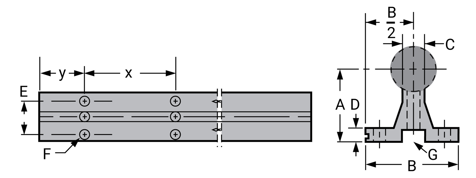
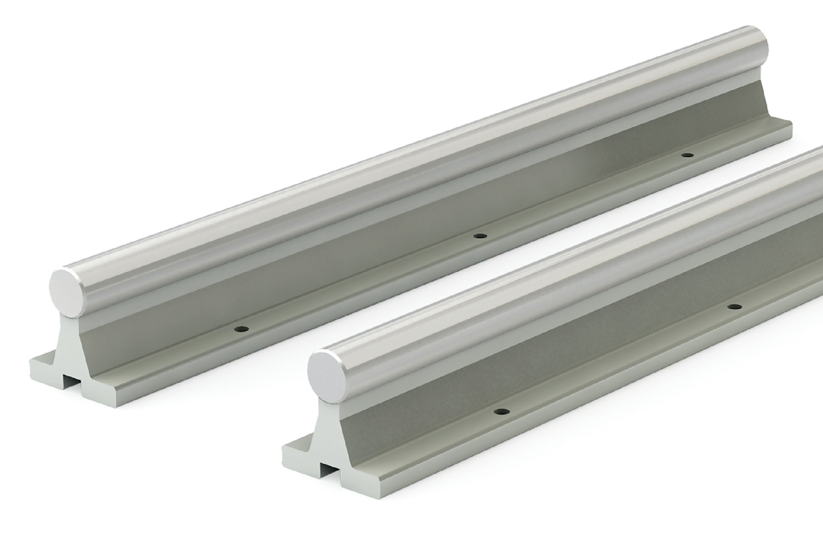
| Part No.* | Nominal Dia. in. |
Diameter Tolerance |
A +/- 0.002 |
B | C | D | E | F | Standard Hole Spacing |
Weight lb./in. |
|||||
|---|---|---|---|---|---|---|---|---|---|---|---|---|---|---|---|
| Shaft Size | Material** | Length | Min | Max | Bolt | Ø | X | Y | |||||||
| SRA08 | ______ | -_ _ _ . _ _ _-SL | 1/2 | 0.4988 | 0.4996 | 1.125 | 1.500 | 0.250 | 0.188 | 1.000 | #6 | 0.169 | 4 | 2 | 0.101 |
| SRA10 | ______ | -_ _ _ . _ _ _-SL | 5/8 | 0.6238 | 0.6246 | 1.125 | 1.625 | 0.313 | 0.250 | 1.125 | #8 | 0.193 | 4 | 2 | 0.145 |
| SRA12 | ______ | -_ _ _ . _ _ _-SL | 3/4 | 0.7488 | 0.7496 | 1.500 | 1.750 | 0.375 | 0.250 | 1.250 | #10 | 0.221 | 6 | 3 | 0.202 |
| SRA16 | ______ | -_ _ _ . _ _ _-SL | 1 | 0.9988 | 0.9996 | 1.750 | 2.125 | 0.500 | 0.250 | 1.500 | 1/4" | 0.281 | 6 | 3 | 0.328 |
| SRA20 | ______ | -_ _ _ . _ _ _-SL | 1-1/4 | 1.2488 | 1.2496 | 2.125 | 2.500 | 0.563 | 0.313 | 1.875 | 5/16" | 0.343 | 6 | 3 | 0.493 |
| SRA24 | ______ | -_ _ _ . _ _ _-SL | 1-1/2 | 1.4987 | 1.4995 | 2.500 | 3.000 | 0.688 | 0.375 | 2.250 | 5/16" | 0.343 | 8 | 4 | 0.711 |
| SRA32 | ______ | -_ _ _ . _ _ _-SL | 2 | 1.9985 | 1.9995 | 3.250 | 3.750 | 0.875 | 0.500 | 2.750 | 3/8" | 0.406 | 8 | 4 | 1.231 |
| SRA48 | ______ | -_ _ _ . _ _ _-SL | 3 | 2.9983 | 2.9992 | 4.000 | 6.000 | 1.400 | 0.750 | 4.250 | 3/4" | 0.630 | 8 | 4 | 2.641 |
*Part Numbers are complete when Material and Length are added.
Default material is 1060 steel when no Material is specified.
**For other steel options add below code into Material location:
CC Ceramic Coated Shafting
SS 440 Stainless Steel
SS 420 Stainless Steel
SS 316 316 Stainless Steel
Example 1: The Complete Part Number for a 1 inch diameter 440 Stainless Steel shaft
of 24 inches is SRA16SS-024.000-SL
Example 2: The Complete Part Number for a ¾ inch diameter 1060 Steel shaft
of 18 inches is SRA12-018.000-SL
Note: Specify length in part number using inches. Example: for 1/2" shafting total length 36" long = SRA08-036.000. Customer specifies 'y' dimension, if different than standard.
Contact PBC Linear for other available hole patterns.
Support Rail – Aluminum SR & SR_PD
Non-Drilled (SR)

Pre-Drilled (SRxxPD)
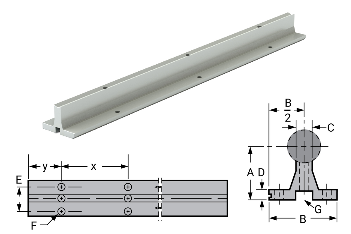
| Part No. | Nominal Dia. In. |
A +/- 0.002 |
B | C | D | E | Standard Hole Spacing |
G Recommended Mounting Hole Size |
Max Length +/- 0.125 |
Weight lb./in. |
||||
|---|---|---|---|---|---|---|---|---|---|---|---|---|---|---|
| Non-Drilled | Pre-Drilled | X | Y | Hole | Screw | Fastener Length |
||||||||
| SR08-xxx.xxx | SR08PD-xxx.xxx | 1/2" | 1.125 | 1.500 | 0.250 | 0.188 | 1.000 | 4 | 2 | 0.169 | 6-32 x 7/8" | 7/8" | 48 | 0.045 |
| SR10-xxx.xxx | SR10PD-xxx.xxx | 5/8" | 1.125 | 1.625 | 0.313 | 0.250 | 1.125 | 4 | 2 | 0.193 | 8-32 x 7/8" | 7/8" | 48 | 0.058 |
| SR12-xxx.xxx | SR12PD-xxx.xxx | 3/4" | 1.500 | 1.750 | 0.375 | 0.250 | 1.250 | 6 | 3 | 0.221 | 10-32 x 7/8" | 7/8" | 48 | 0.077 |
| SR16-xxx.xxx | SR16PD-xxx.xxx | 1" | 1.750 | 2.125 | 0.500 | 0.250 | 1.500 | 6 | 3 | 0.281 | 1/4-20 x 1-1/2" | 1-1/2" | 48 | 0.104 |
| SR20-xxx.xxx | SR20PD-xxx.xxx | 1-1/4" | 2.125 | 2.500 | 0.563 | 0.313 | 1.875 | 6 | 3 | 0.343 | 5/16-18 x 1-3/4" | 1-3/4" | 48 | 0.145 |
| SR24-xxx.xxx | SR24PD-xxx.xxx | 1-1/2" | 2.500 | 3.000 | 0.688 | 0.375 | 2.250 | 8 | 4 | 0.406 | 3/8-16 x 2" | 2" | 48 | 0.210 |
| SR32-xxx.xxx | SR32PD-xxx.xxx | 2" | 3.250 | 3.750 | 0.875 | 0.500 | 2.750 | 8 | 4 | 0.531 | 1/2-13 x 2-1/2" | 2-1/2" | 48 | 0.342 |
| SR48-xxx.xxx | SR48PD-xxx.xxx | 3 | 4.000 | 6.000 | 1.400 | 0.750 | 4.250 | 8 | 4 | 0.625 | 3/4-10 x 3-1/4" | 3" | 48 | 0.638 |
Notes:
(1) Specify length in part number. Example: for 1/2" shafting support rail to 24" length = SR08-024.000 (Aluminum alloy construction, no coating).
(2) Shafts and support rails sold separately. Customer specifies 'y' dimension. Shaft rails and assemblies are available in long lengths, consult factory.
(3) Contact PBC Linear for other available hole patterns.
Rail Assembly – Ceramic Coated CCR
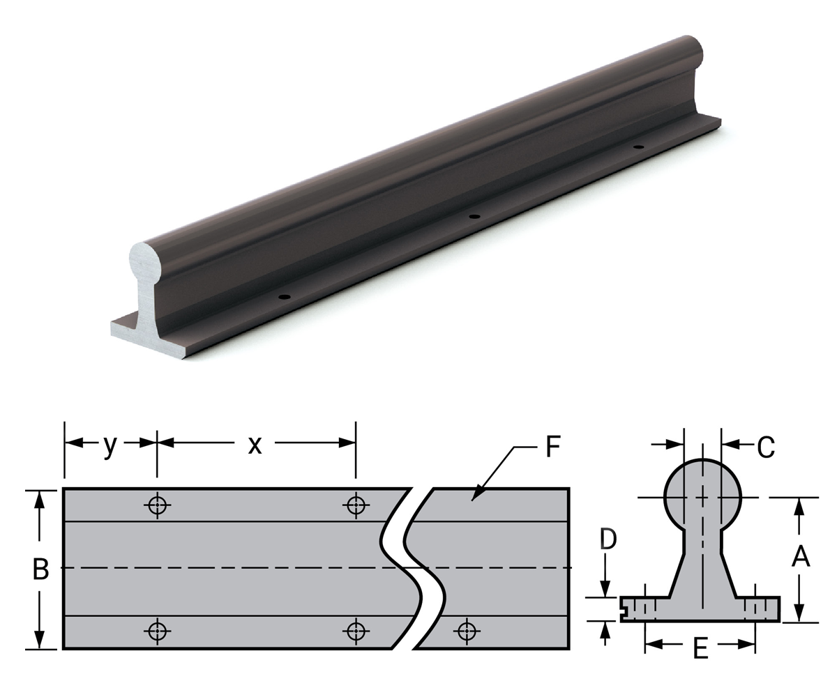
- Ceramic-like coating provides hardness up to RC70 and increased corrosion resistance
- Optimized for FrelonGOLD® liners
- NOT to be used with linear ball bearings (Does not apply to linear guide products – MR, UG, UGA, etc)
- Economical, lightweight alternative to traditional steel shafting
- One-piece integrated design eliminates assembly time
- Weld splatter, paints, and contaminants will not stick
- Non-magnetic and vibration resistant
- Pre-drilled with stand X hole spacing*
| Part No. | Nominal Dia. In. |
Diameter Tolerance | A +/- 0.002 |
B | C | D | E | F | Standard Hole Spacing |
Max Length in. |
Weight lb./in. |
|||
|---|---|---|---|---|---|---|---|---|---|---|---|---|---|---|
| MIN | MAX | Bolt | Hole | X | Y | |||||||||
| CCR08-xxx.xxx | 1/2 | 0.4988 | 0.4996 | 1.125 | 1.500 | 0.250 | 0.188 | 1.000 | #6 | 0.169 | 4 | 2 | 120 | 0.019 |
| CCR10-xxx.xxx | 5/8 | 0.6238 | 0.6246 | 1.125 | 1.625 | 0.313 | 0.250 | 1.125 | #8 | 0.193 | 4 | 2 | 120 | 0.030 |
| CCR12-xxx.xxx | 3/4 | 0.7488 | 0.7496 | 1.500 | 1.750 | 0.375 | 0.250 | 1.250 | #10 | 0.221 | 6 | 3 | 120 | 0.043 |
| CCR16-xxx.xxx | 1 | 0.9988 | 0.9996 | 1.750 | 2.125 | 0.500 | 0.250 | 1.500 | 1/4" | 0.281 | 6 | 3 | 120 | 0.076 |
| CCR20-xxx.xxx | 1-1/4 | 1.2488 | 1.2496 | 2.125 | 2.500 | 0.563 | 0.313 | 1.875 | 5/16" | 0.343 | 6 | 3 | 120 | 0.119 |
| CCR24-xxx.xxx | 1-1/2 | 1.4987 | 1.4995 | 2.500 | 3.000 | 0.688 | 0.375 | 2.250 | 5/16" | 0.343 | 8 | 4 | 120 | 0.172 |
| CCR32-xxx.xxx | 2 | 1.9985 | 1.9995 | 3.250 | 3.750 | 0.875 | 0.500 | 2.750 | 3/8" | 0.406 | 8 | 4 | 120 | 0.305 |
Notes:
(1) Specify length in part number using inches. Example: for 1/2” shafting total length 36” long = CCR08-036.000.
(2) Cut-to-length rails may not be coated on the ends.
(3) Contact PBC Linear for other available hole patterns.
DO NOT use with linear ball bearings or roller pillow block assemblies.
*Customer specified ‘Y’ dimension.
Shafting Low Support Rails
Low Support Rail - Steel LSR
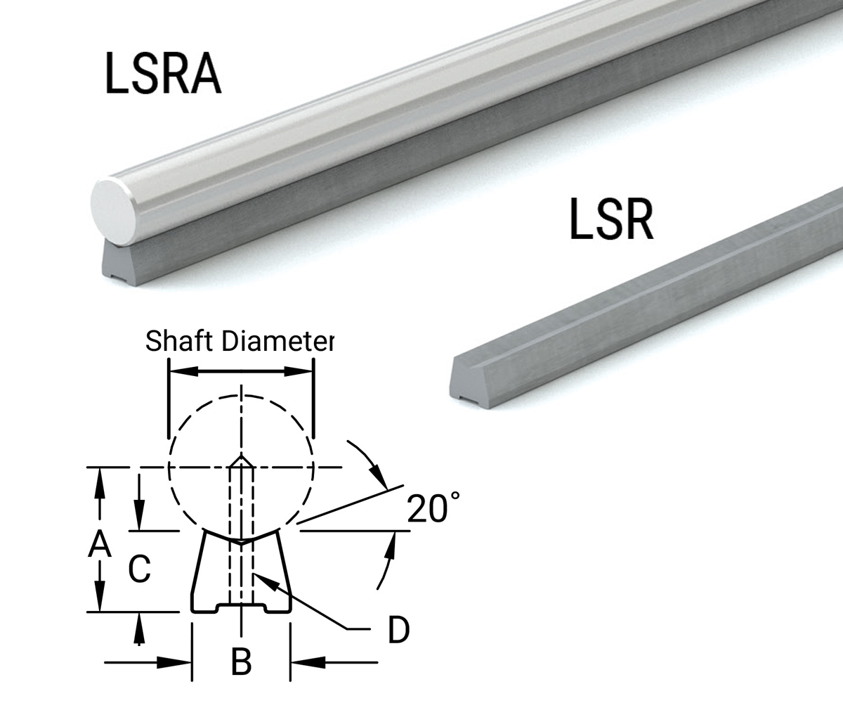
The AISI C-1018 steel LSR shaft support is a low support rail with a reduced footprint, and 40% lower profile than other support rails. This is an excellent choice for applications requiring compact low shaft support. The standard length for LSR type supports is 48".
- No coating
- Length tolerance +0", -1/8"
| Part No. | Assembly Part No. |
Shaft Dia. in. |
A +/- 0.002 |
B +/- 0.005 |
C (Ref) |
D | Hole Spacing For LSR-Pd Pre-Drilled |
Weight Per 48" (Approximate) |
Assembly Weight Per 48" (Approximate) |
||
|---|---|---|---|---|---|---|---|---|---|---|---|
| Bolt | Hole | Y | X | lb. +/- 0.001 | lb. +/- 0.001 | ||||||
| LSR-8 LSR-8-PD | LSRA-8 | 1/2 | 0.562 | 0.370 | 0.341 | 6-32 | 0.169 | 2 | 4 | 1.320 | 3.960 |
| LSR-10 LSR-10-PD | LSRA-10 | 5/8 | 0.687 | 0.450 | 0.412 | 8-32 | 0.193 | 2 | 4 | 1.950 | 6.078 |
| LSR-12 LSR-12-PD | LSRA-12 | 3/4 | 0.750 | 0.510 | 0.420 | 10-32 | 0.221 | 3 | 6 | 2.250 | 8.250 |
| LSR-16 LSR-16-PD | LSRA-16 | 1 | 1.000 | 0.690 | 0.560 | 1/4-20 | 0.281 | 3 | 6 | 4.250 | 14.910 |
| LSR-20 LSR-20-PD | LSRA-20 | 1-1/4 | 1.187 | 0.780 | 0.626 | 5/16-18 | 0.343 | 3 | 6 | 5.080 | 21.780 |
| LSR-24 LSR-24-PD | LSRA-24 | 1-1/2 | 1.375 | 0.930 | 0.703 | 3/8-16 | 0.406 | 4 | 8 | 6.720 | 30.720 |
| LSR-32 LSR-32-PD | LSRA-32 | 2 | 1.750 | 1.180 | 0.845 | 1/2-13 | 0.531 | 4 | 8 | 11.000 | 53.720 |
| LSR-48 LSR-48-PD | LSRA-48 | 3 | 2.750 | 1.875 | 1.404 | 3/4-10 | 0.812 | 4 | 8 | 27.920 | 124.060 |
How to order
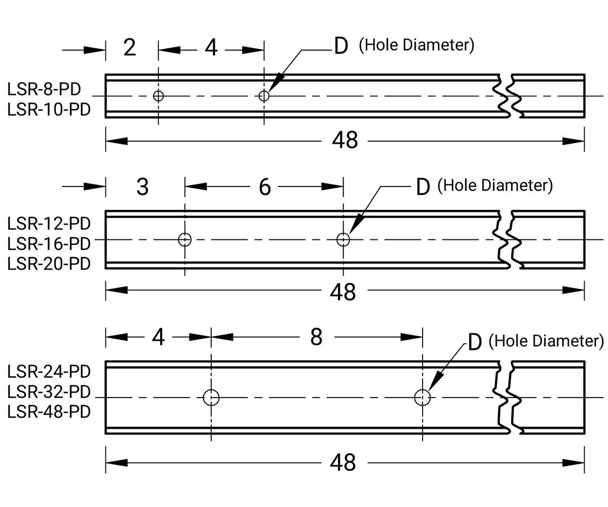
Available as cut to length options up to a max length of 144". Example: 48" would be LSR12-048.000-SL.
If standard mounting holes are required, specify low shaft rails with pre-drilled mounting holes by part number. Example: LSR-12-PD. Hole sizes and spacings are shown in the table.
If other than standard hole spacing is required, please provide drawings with all dimensions, tolerances, and quantity. With or without mounting holes, low shaft rails will be supplied in 48" lengths when ordered by part number.
Low Support Rail & Shaft Set LSG
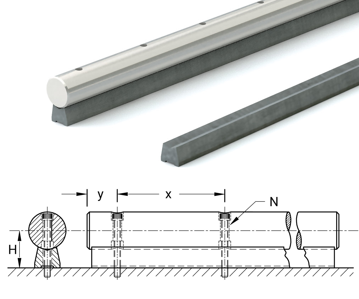
Precision case hardened and ground shaft, plus an LSR steel support rail, effectively doubles the life of the shaft by allowing it to be turned over for a fresh surface when wear becomes evident. Both sides of the shaft are counterbored so the shaft may be rotated 180°, and rebolted for use on the new side. This guide is sold as a two-piece set; the shaft and support are not assembled. The guide is then bolted down through the top of the shaft to reduce installation time. The shafts are also available in 400 series stainless steel. Drilled through and counterbored shafts may not be suitable for all linear bearings.
- No coating
| Part No. | Shaft Dia. in. |
H in. |
B in. |
Y in. |
X in. |
N in. |
Weight Per in. lb. |
|---|---|---|---|---|---|---|---|
| LSG-10 | 5/8 | 0.687 | 0.450 | 2 | 4 | #5 | 0.132 |
| LSG-12 | 3/4 | 0.750 | 0.510 | 3 | 6 | #6 | 0.171 |
| LSG-16 | 1 | 1.000 | 0.690 | 3 | 6 | #10 | 0.311 |
| LSG-20 | 1-1/4 | 1.187 | 0.780 | 3 | 6 | 5/16 | 0.454 |
| LSG-24 | 1-1/2 | 1.375 | 0.930 | 4 | 8 | 3/8 | 0.640 |
| LSG-32 | 2 | 1.750 | 1.180 | 4 | 8 | 1/2 | 1.119 |
Notes: Customer specifies 'y' dimension.
Custom Machining Options for Shafts
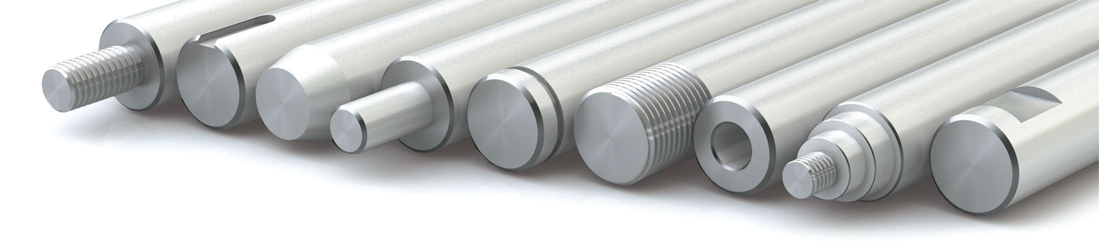
Special Machining
Standard 60 Plus shafting, which is available from stock, can be cut with special length tolerances. 60 Plus shafting may also be drilled with a variety of radial holes and tapped if needed. Shafts can be supplied with flats, keyways, and reduced diameters. Shafts can also be plated.
There is an extra charge for all special machining operations. For specific prices, send your drawing or technical description to PBC Linear.
Special Length Tolerances
Standard length tolerances for shafting are:
| < 1 1/4" diameter | ± 1/32" (± 0.03") |
| 1 3/8"-2" diameter | ± 1/16" (± 0.06") |
| > 2" diameter | ± 1/8" (± 0.125") |
All SR, LSR, SRA, LSRA, and CCR are +0.000"/-0.125".
Contact us with special requirements
Special Straightness Tolerances
PBC Linear standard length tolerances are 0.001 to 0.002"/ft cumulative. Except for 3/8" diameters and less. Contact us with special requirements.
Standard Chamfers
| Diameter | Size | Tolerance |
|---|---|---|
| ≤ 3/8" | Break Edge | ± 0.005–0.010" x 45° |
| 10 mm–7/8" | 1/32" x 45° | ± 0.005" |
| 1"–2" | 1/16" x 45° | ± 0.010" |
| 2 1/2"–3" | 1/8" x 45° | ± 0.010" |
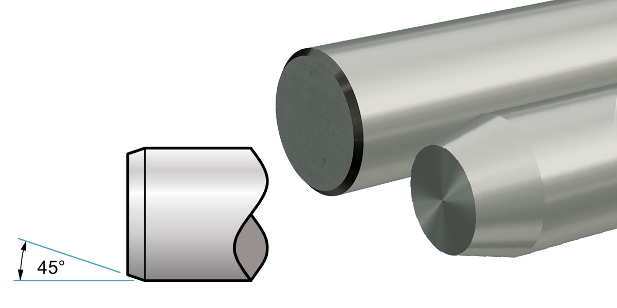
Special chamfer at any angle can be supplied for an additional charge.
Machining Shaft Ends
Certain complex machined ends may require annealing. Consult the factory on whether annealing is needed for your custom machined end. Customer must specify if they want to forgo the annealing for their custom machined end.
Contact the factory for special options.
Radial Holes Drilled and Tapped to Center of Shaft
- U.N.C. or U.N.F.
- Class 2-B thread.
| Hole to Hole | ± 0.010" Non-Accum |
| Hole to Centerline | ± 0.0075" |
| Hole to End | ± 0.030" (± 0.06 mm) |
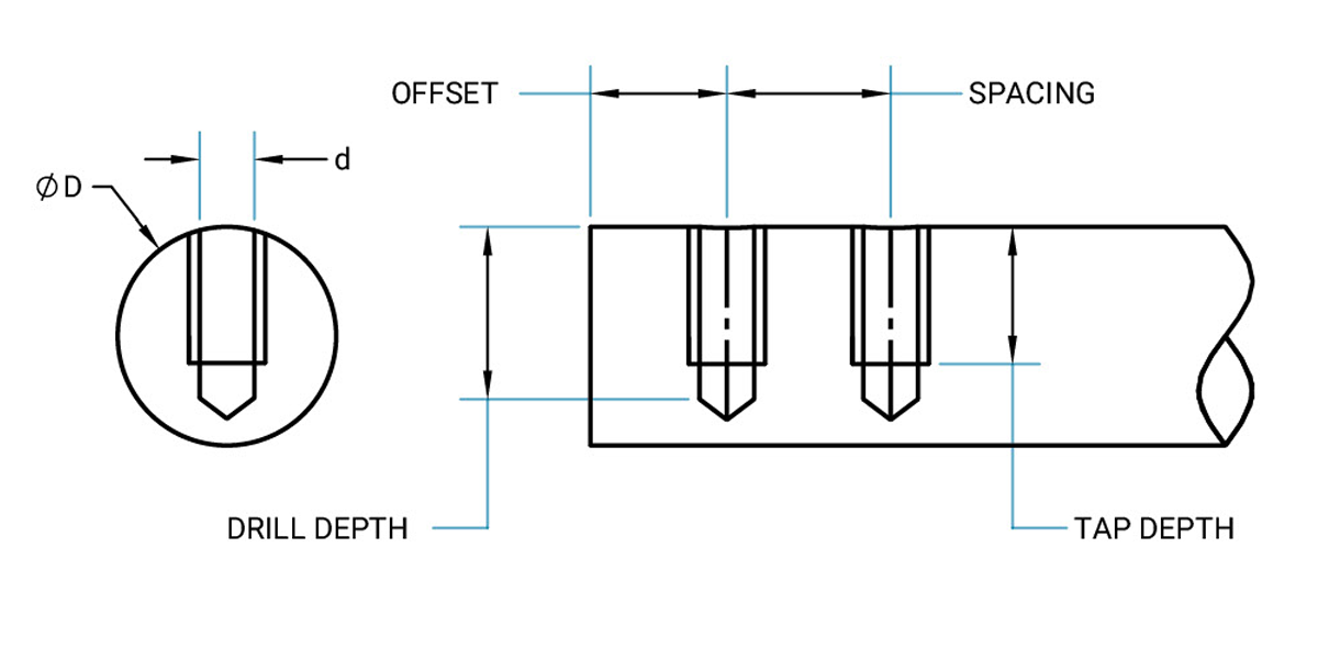
Note: Hole depth full threads to 1/2" of the shaft diameter.
Radial Holes Drilled and Tapped through Shaft
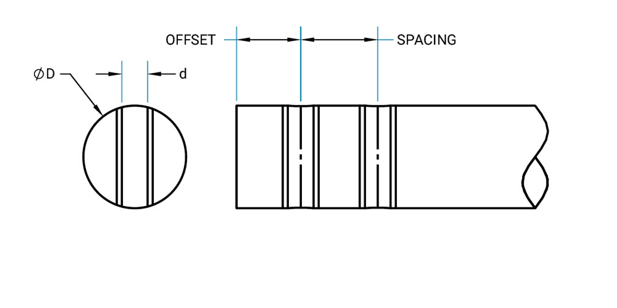
Radial Holes Drilled through Shaft
| Hole Diameter | ± 0.005" |
| Hole to Hole | ± 0.010" Non-Accum |
| Hole to Centerline | ± 0.0075" |
| Hole to End | ± 0.030" |
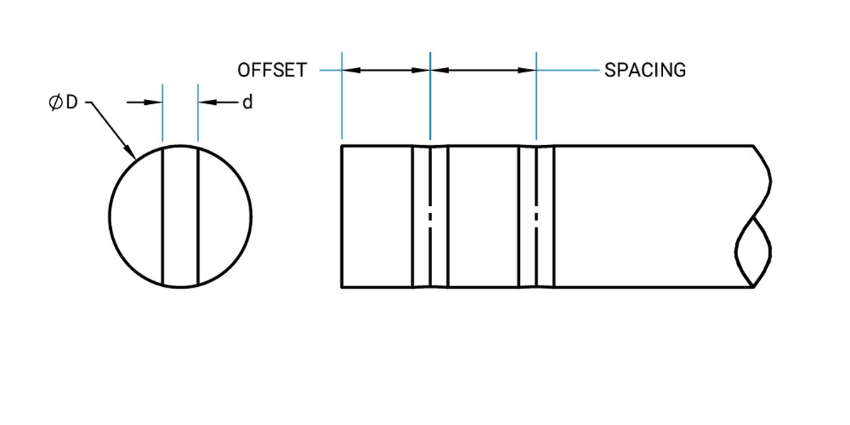
Radial Holes Drilled and Reamed through Shafts
| Hole Diameter | ± 0.001" |
| Hole to Hole | ± 0.010" Non-Accum |
| Hole to Centerline | ± 0.0075" |
| Hole to End | ± 0.030" |
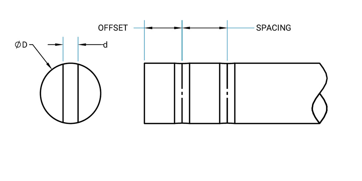
Threaded Shaft Diameter
Standard threads are either Unified National Coarse or Unified National Fine, Class 2-A fit. Shafts will be annealed and soft around the circumference of threaded areas within the case
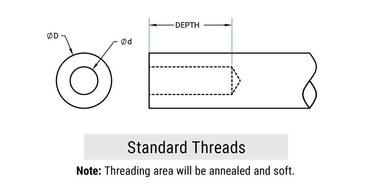
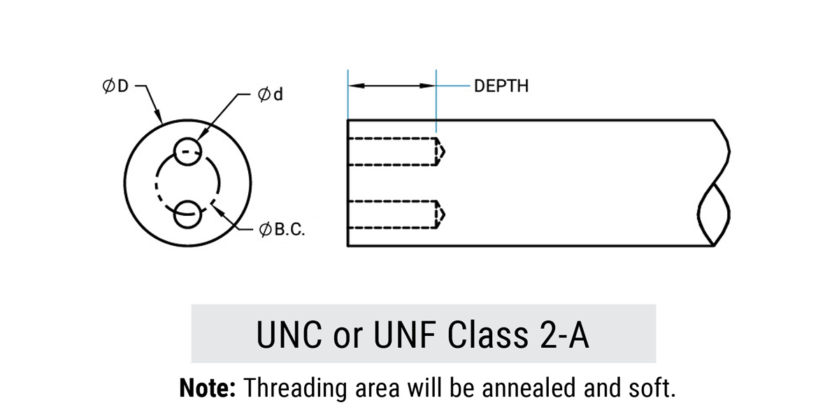
Reduced Shaft Diameter
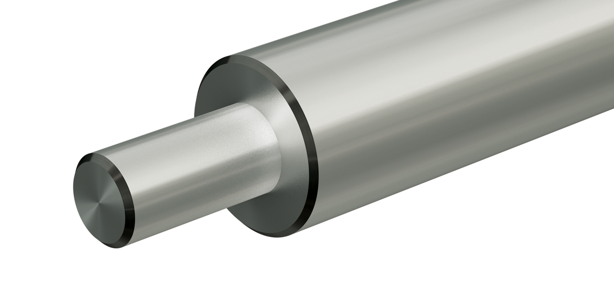
Standard diameter tolerances on turned down diameters are ± 0.001". Special tolerances of ± 0.0001" are available. Runout is within 0.001" total indicator reading. Two-step shaft diameter reduction is also available.
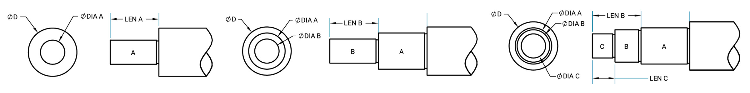
| Normal Tolerance | ± 0.001" |
| Concentricity | ± 0.002" MAX T.I.R |
Coaxial Holes Drilled and Tapped in Center of End of Shaft
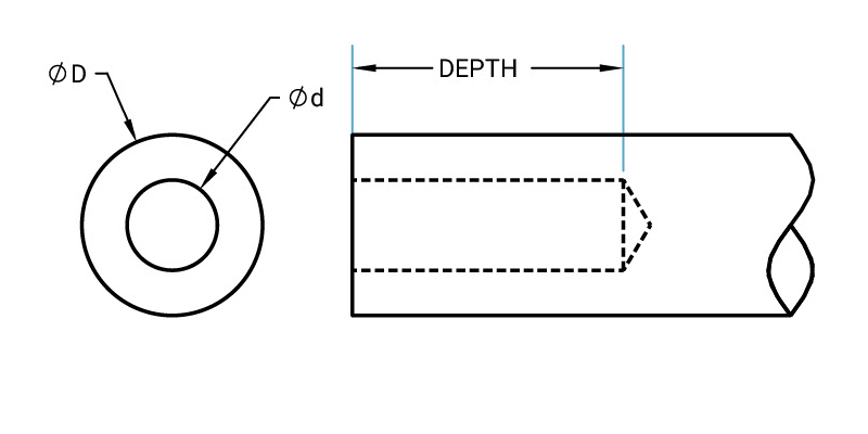
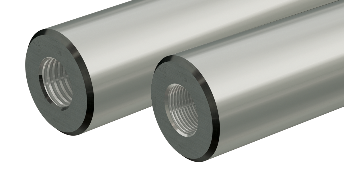
| Concentricity | 0.01" |
| Diameter of Holes | ± 0.006" |
| Bored Holes | ± 0.001" |
| Bolt Circles | ± 2° |
| Coaxial on Both Ends | OAL ± 0.015" |
| Axial on One End | OAL ± 0.030" |
Note: Depth is twice the diameter of the tap minimum.
Dowel Joints
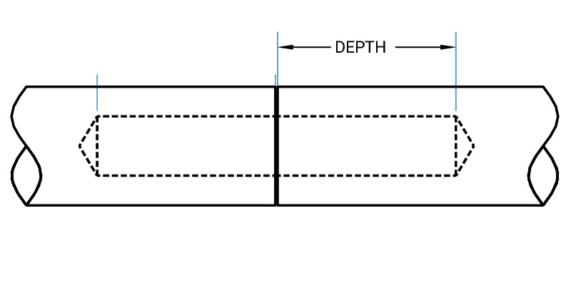
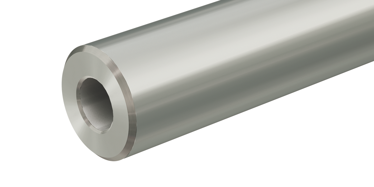
Match over joint of 0.002 Maximum TIR
| All Linear Dimensions | ± 0.010" |
| First Hole | ± 0.0075" |
| Shaft Diameter | 5/8" to 3" |
Note: Ends machined square without chamfer.
Retaining Ring Groove
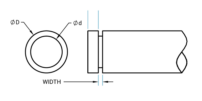
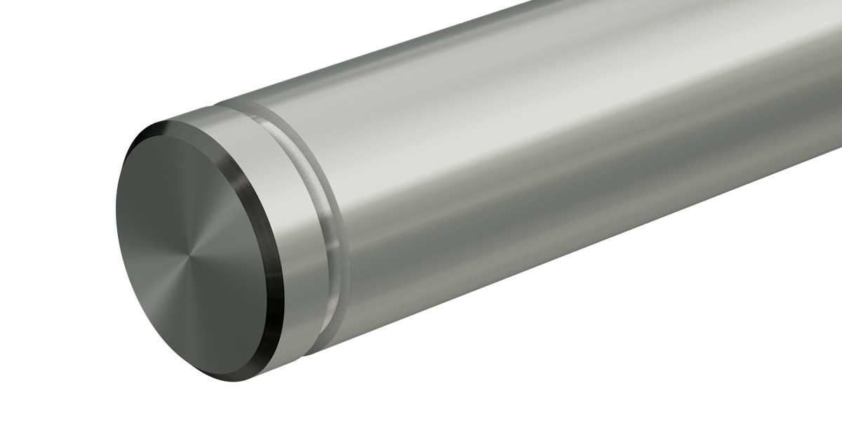
| Location Tolerance | ± 0.062" Standard |
| ± 0.005" Custom |
Butted Joints
Ends machined square, no chamfer. Available for all nominal shaft diameters.
| Perpendicularity | ± 0.001" MAX |
| All Linear Dimensions | ± 0.010" |
Note: Ends machined square without chamfer.
Flat(s) on Shaft
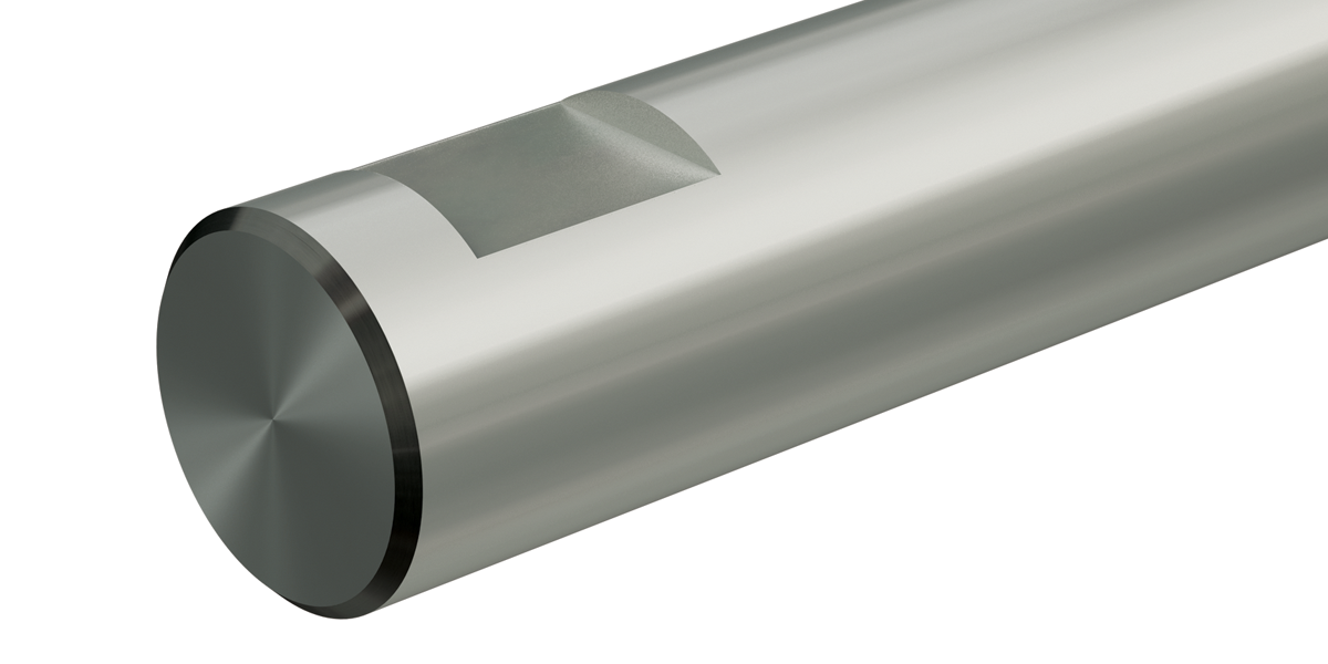
Flats are available. Flats extending over a large portion of the shaft or the entire length of the shaft are not available. Cutting into the hardened layer would cause considerable warping, and subsequent straightening costs would be prohibitive.
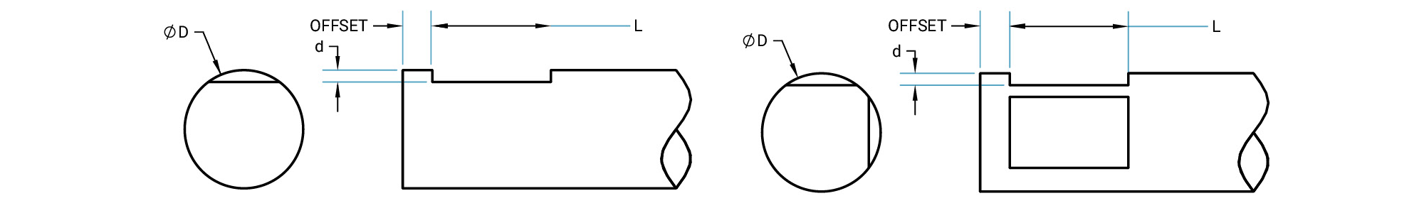
| Location Tolerance | ± 0.010" |
Note: Bottom corners of flat will have a 0.030" radius due to manufacturing process.
Keyways
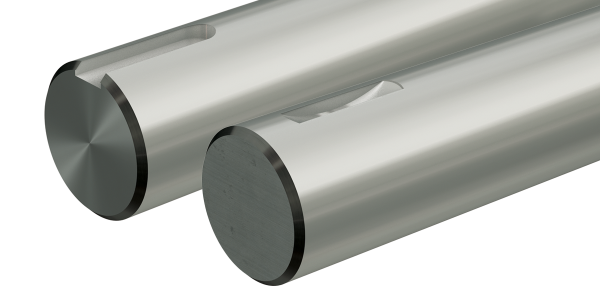
Keyways may be square, flat or American Standard Woodruff. Available for nominal shaft diameters from 1/2" through 4".
Other options available. Contact us for a quote.
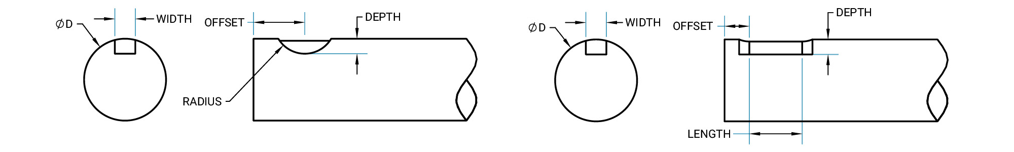
| Width | ± 0.001" |
| Length | ± 0.010" |
| Linear Locations | ± 0.010" |
| Location to C/L | ± 0.0075" |
| Depth | 1/2" width + “M” on table 8 |
Note: Square or American Standard Woodruff. Maximum length in house is 48".
Simplicity Square Bearings and Shafting
Product Overview
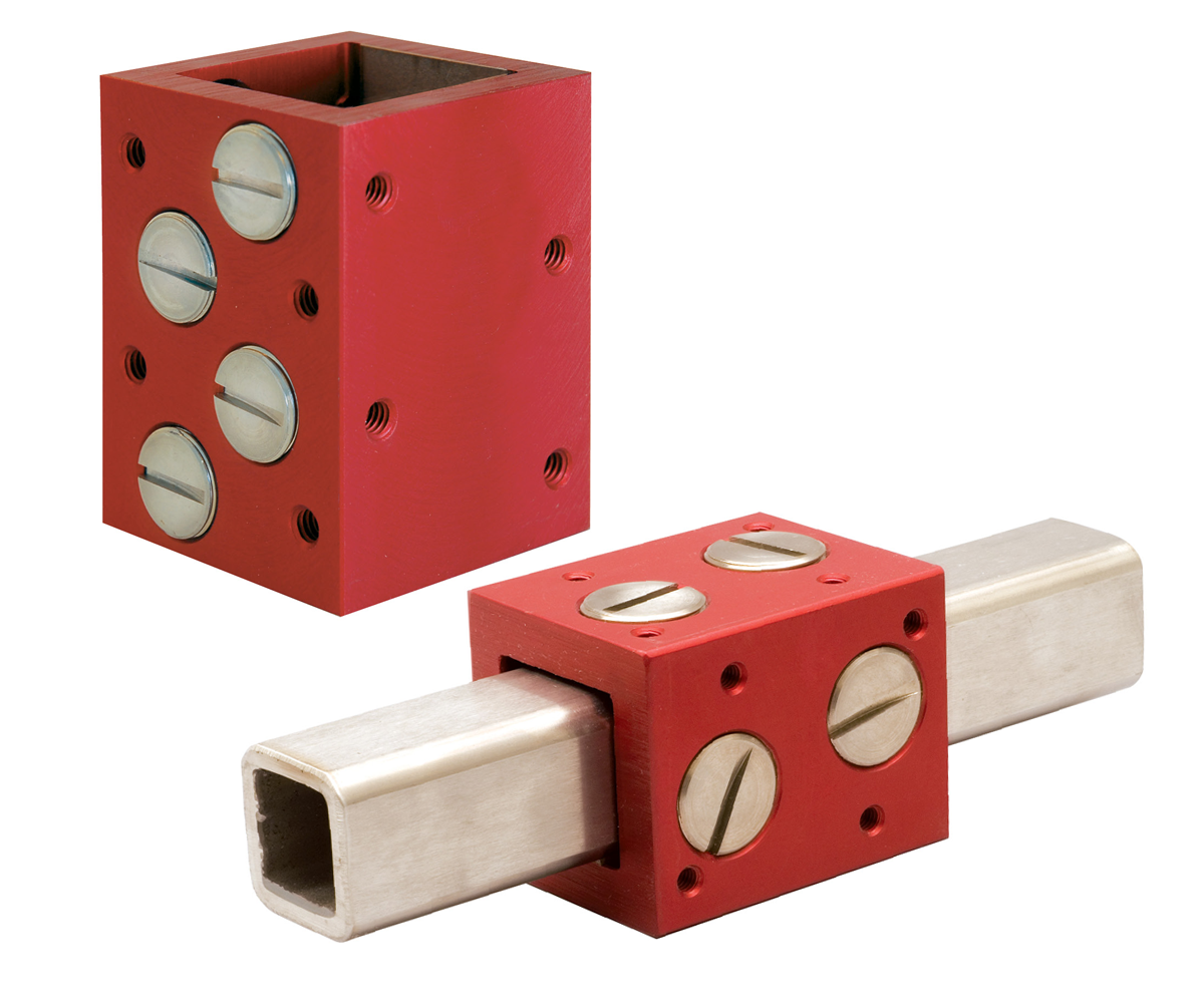
- Runs on a single, square shaft eliminating costly components
- Maintains radial integrity and can eliminate the need for parallel shafting
- Can be mounted in any orientation
- Housings are aluminum alloy with a standard anodized finish
- Utilizes standard bearing plugs
- Adjustable to maintain tight running clearances, contingent upon shafting
- Bearing plugs are easily replaced
Same characteristics of the standard round-way Simplicity bearings:
- Self-lubricating
- High load capacity
- Wide temperature range: (-400°F/+400°F) (-240°C/+204°C)
- Excel in contaminated environments
- High shock loading abilities
- Low wear rates
Adjustable Bearing Plugs
Bearing material: Part number APN16E plug with Frelon® J is standard for PST stainless steel square shafting. Part number APN16 plug with FrelonGOLD® is also available for applications to be run on steel. Plug material is 316 stainless steel.
- Bearing plugs can be purchased separately
- Ideal for use in many applications as a wear pad
- Bearing surface area = 0.300 in²
- Max static load capacity per plug (Frelon J) = 450 lb.
- The use of green Loctite or similar is recommended to hold the adjustable bearing plugs in position while allowing relative ease of adjustment
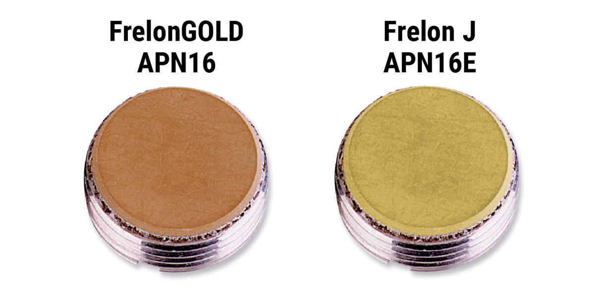
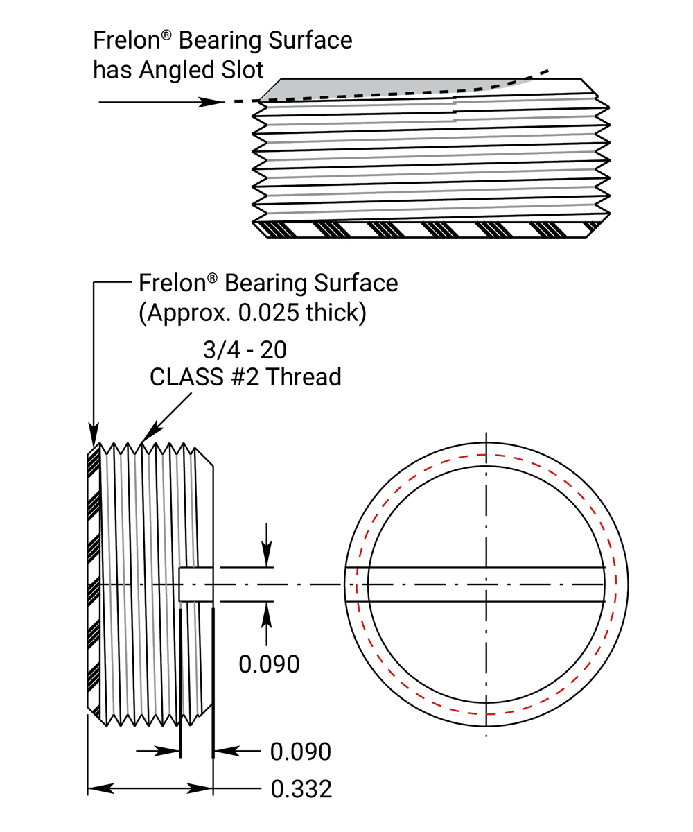
Ordering Information
| Part No. | Description |
|---|---|
| APN16E | Standard: Adjustable bearing plug with Frelon J bearing liner. Use with 300 series stainless or soft shafting. |
| APN16 | Optional: Adjustable bearing plug with FrelonGOLD bearing liner. Use with steel shafting. |
Simplicity Square Shafting, Bearings
& Plugs
Square Bearing Cutaway View
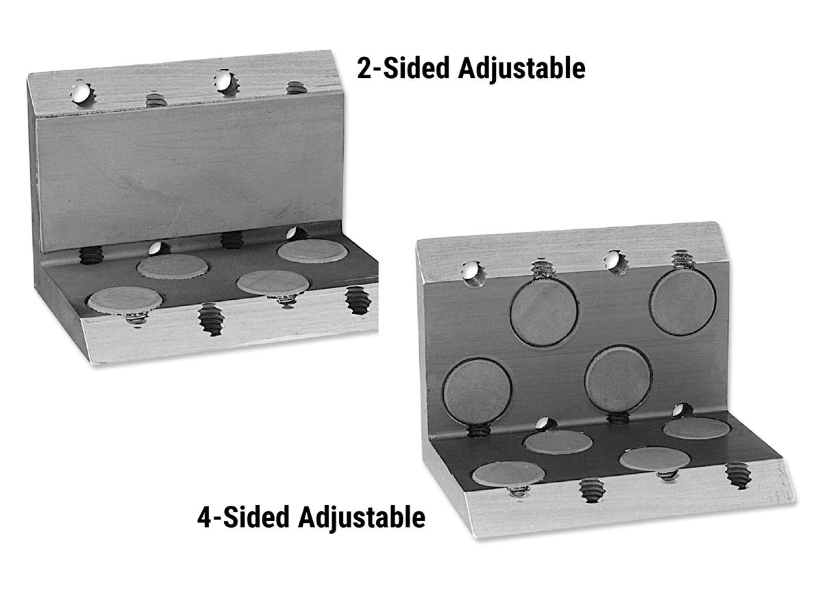
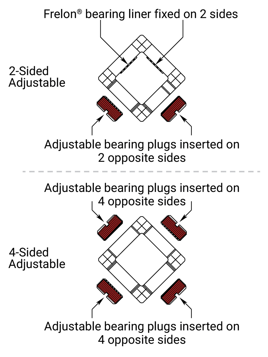
Application Note
Use removable Loctite thread locker to hold the adjustable bearing plugs in position.
Two parameters must be met in the design and use of square bearings:
- The 2:1 ratio for cantilevered loads applies to square bearings in the same way as roundway Simplicity® bearings. Binding will occur if the ratio is not met.
Note: If only one bearing is used, the 2:1 applies from plug centers.
- The maximum load and moment load must be met. To calculate the acceptable cantilever or lever arm, multiply the length (from center of the bearing to the center of the load) times the weight. The result must be less than the moment load for that orientation.
Example: Distance of cantilever = 3"; Amount of load = 40 lb.; 3" x 80 lb. = 240 in-lb.
Square Bearing Load Information
| Part No. | MAX Moments Torsional Capacities in.-lb. |
Max Force lb. |
|
|---|---|---|---|
| Mx | My | F | |
| SB16 | 74 | 165 | 920 |
| SBL16 | 74 | 475 | 920 |
| SB24 | 416 | 402 | 1840 |
| SBL24 | 416 | 1413 | 1840 |
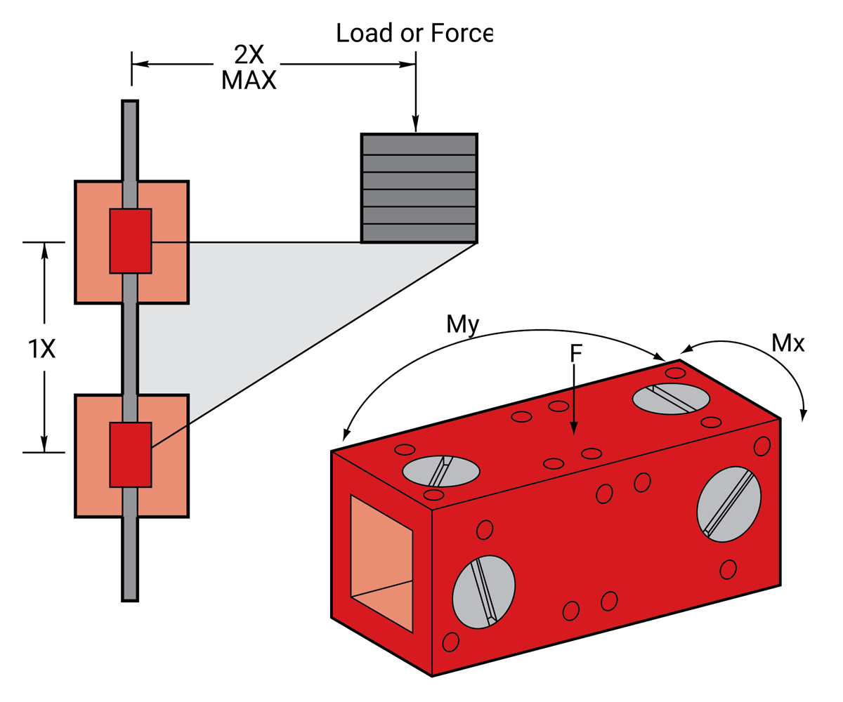
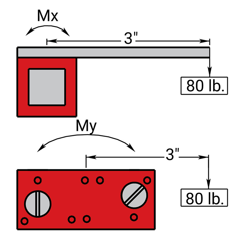
Simplicity Square Bearings • 1.0 Inch
Ordering Information
| Part No. | Description | Bearing Weight lb. |
|---|---|---|
| SB16-2E | Standard 1.0" two-sided adjustable square bearing with Frelon® J plugs for stainless steel shafting. |
0.48 |
| SB16-2 | Optional 1.0" two-sided adjustable square bearing with FrelonGOLD® plugs for steel shafting. |
0.48 |
| SB16-4E | Standard 1.0" four-sided adjustable square bearing with Frelon® J plugs for stainless steel shafting. |
0.56 |
| SB16-4 | Optional 1.0" four-sided adjustable square bearing with FrelonGOLD® plugs for steel shafting. |
0.56 |
| SBL16-2E | Standard 1.0" extended length, two-sided adjustable square bearing with Frelon® J plugs for stainless steel shafting. |
0.77 |
| SBL16-2 | Optional 1.0" extended length, two-sided adjustable square bearing with FrelonGOLD® plugs for steel shafting. |
0.77 |
| SBL16-4E | Standard 1.0" extended length, four-sided adjustable square bearing with Frelon® J plugs for stainless steel shafting. |
0.85 |
| SBL16-4 | Optional 1.0" extended length, four-sided adjustable square bearing with FrelonGOLD® plugs for steel shafting. |
0.85 |
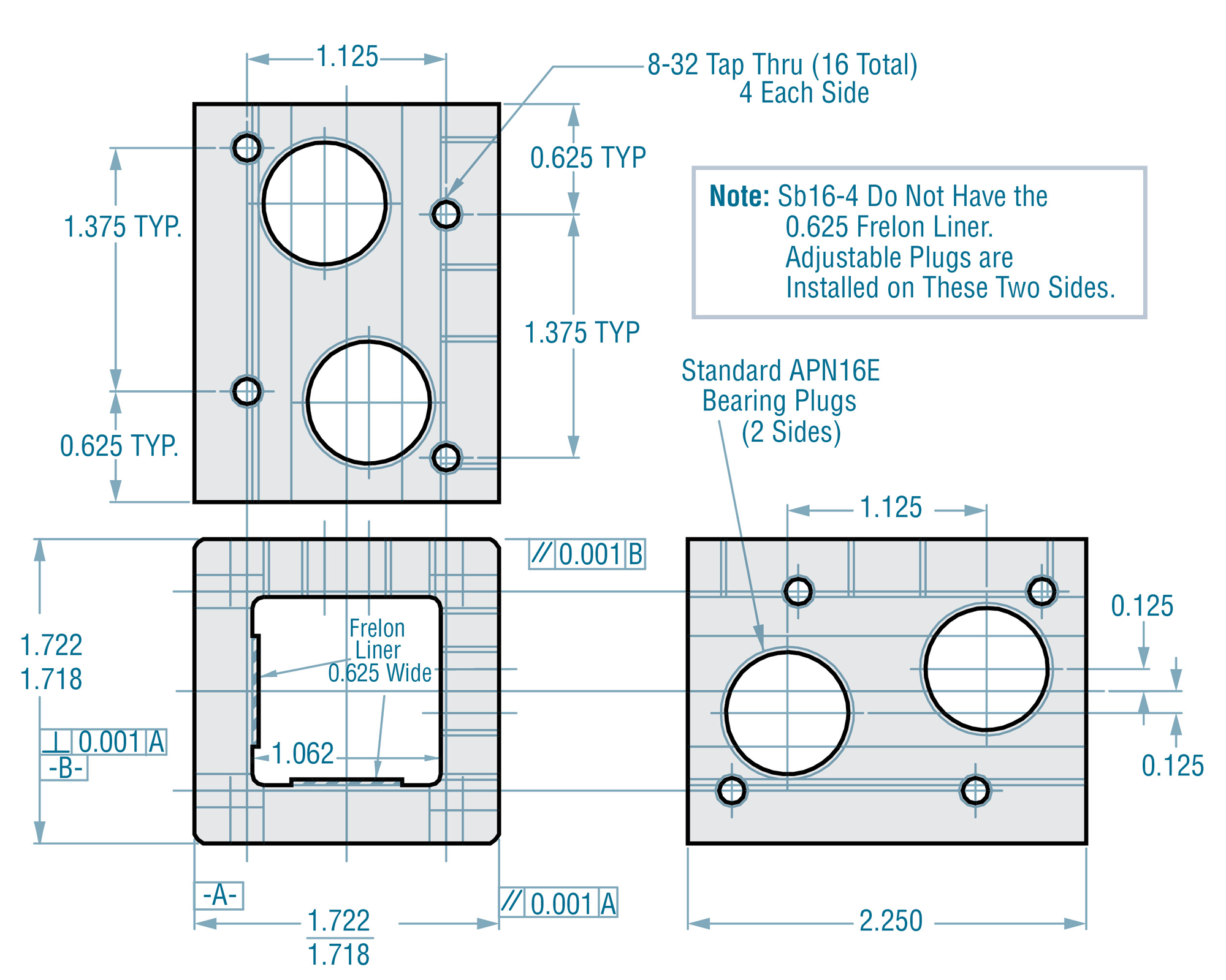
SB16-2 1.0" 2-sided adjustable square bearing
SB16-4 1.0" 4-sided adjustable square bearing
SBL16-2 1.0" Extended length 2-sided adjustable square bearing
SBL16-4 1.0" Extended length 4-sided adjustable square bearing
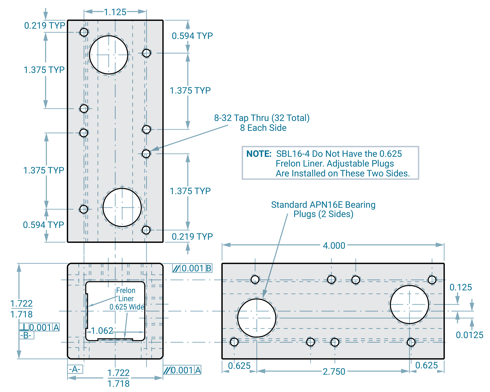
Simplicity Square Bearings • 1.5 Inch
Ordering Information
| Part No. | Description | Bearing Weight lb. |
|---|---|---|
| SB24-2E | Standard 1.5" two-sided adjustable square bearing with Frelon® J plugs for stainless steel shafting. |
0.96 |
| SB24-2 | Optional 1.5" two-sided adjustable square bearing with FrelonGOLD® plugs for steel shafting. |
0.96 |
| SB24-4E | Standard 1.5" four-sided adjustable square bearing with Frelon® J plugs for stainless steel shafting. |
1.12 |
| SB24-4 | Optional 1.5" four-sided adjustable square bearing with FrelonGOLD® plugs for steel shafting. |
1.12 |
| SBL24-2E | Standard 1.5" extended length, two-sided adjustable square bearing with Frelon® J plugs for stainless steel shafting. |
1.71 |
| SBL24-2 | Optional 1.5" extended length, two-sided adjustable square bearing with FrelonGOLD® plugs for steel shafting. |
1.71 |
| SBL24-4E | Standard 1.5" extended length, four-sided adjustable square bearing with Frelon® J plugs for stainless steel shafting. |
1.84 |
| SBL24-4 | Optional 1.5" extended length, four-sided adjustable square bearing with FrelonGOLD® plugs for steel shafting. |
1.84 |
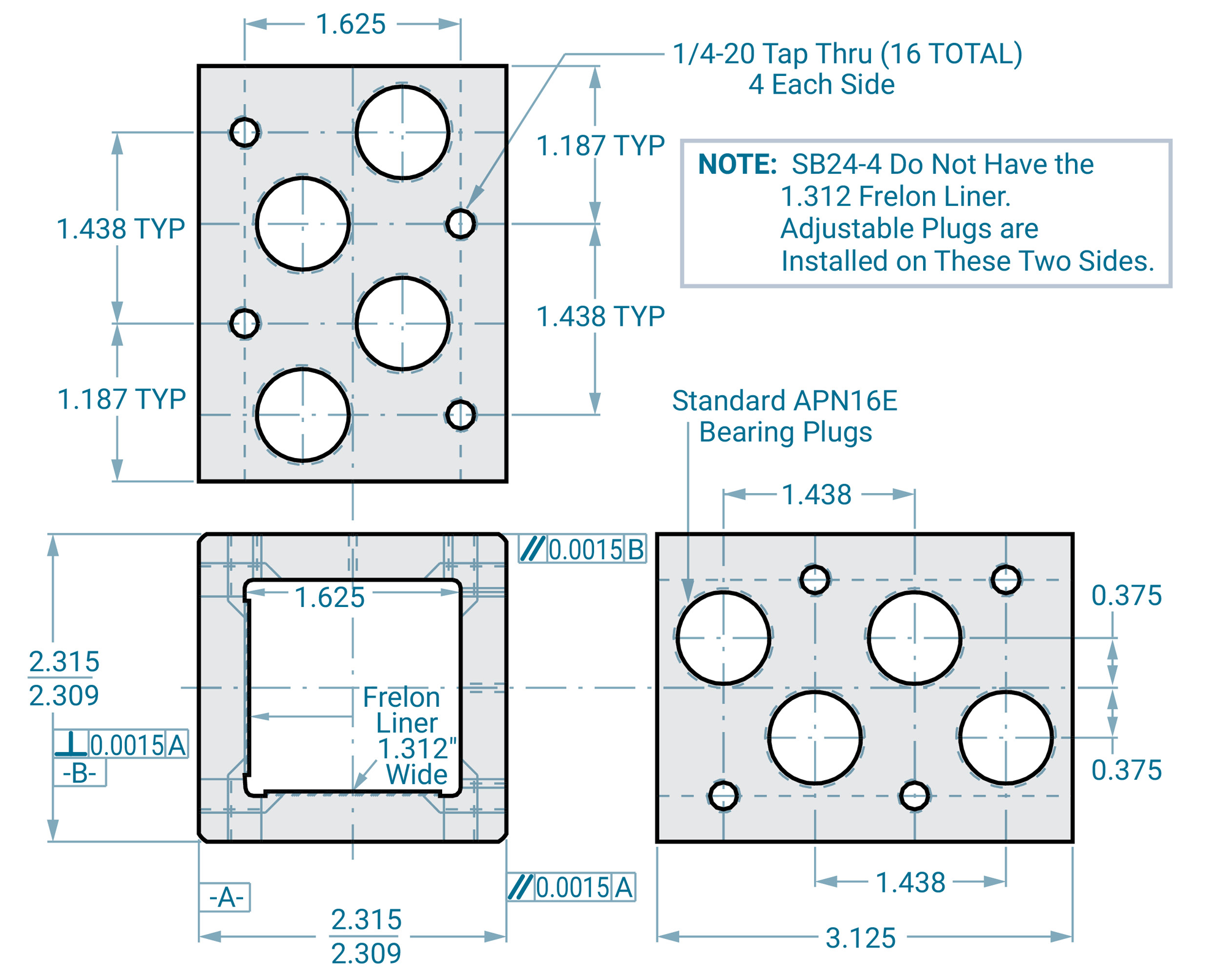
SB24-2 1.5" 2-sided adjustable square bearing
SB24-4 1.5" 4-sided adjustable square bearing
SBL24-2 1.5" Extended length 2-sided adjustable square bearing
SBL24-4 1.5" Extended length 4-sided adjustable square bearing
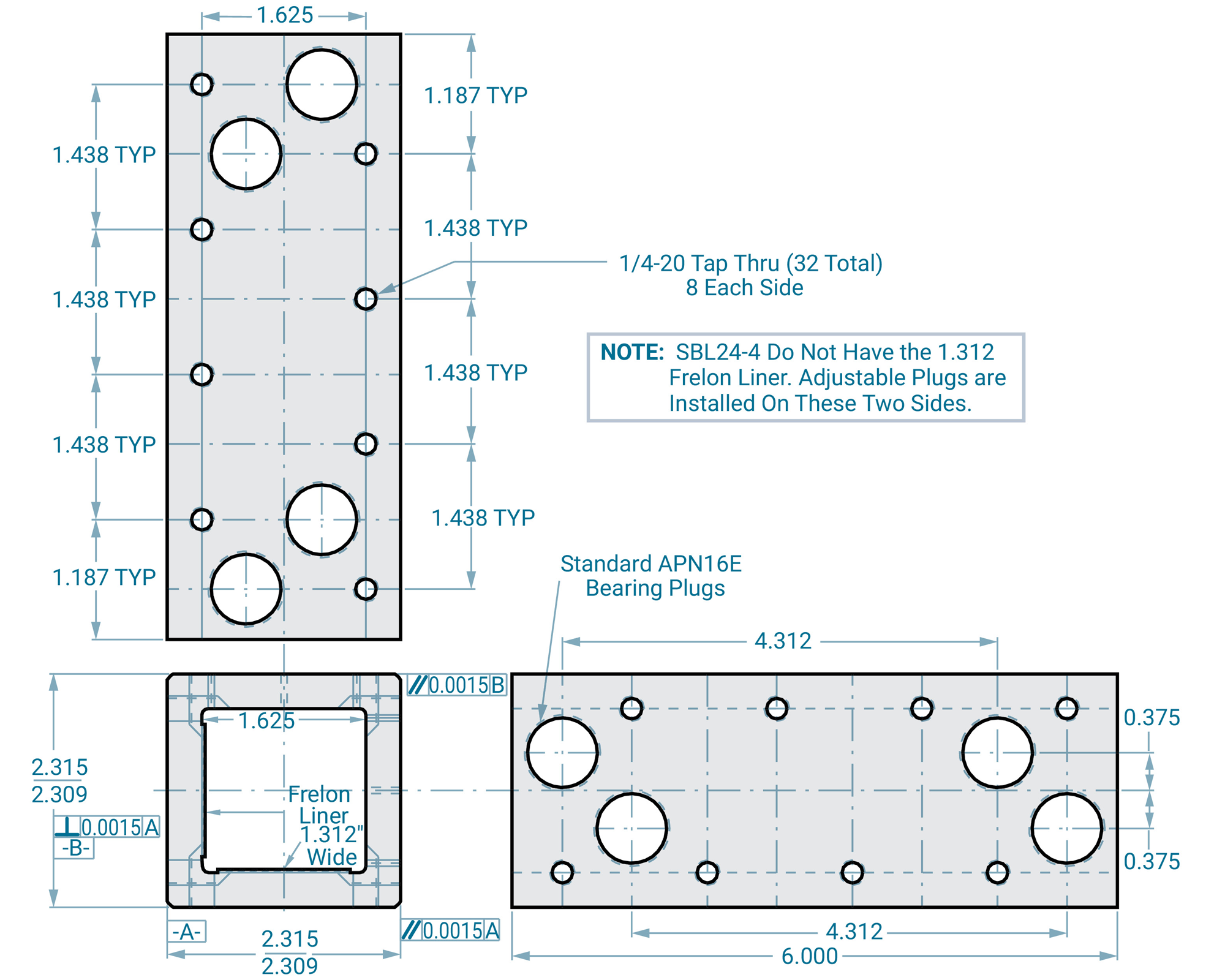
Simplicity Square Shafting
& Accessories
Square Shafting
- 304 Stainless steel (standard) is highly corrosion resistant
- Buffed and polished to provide an excellent running surface for Frelon® J
- Both 1" and 1.5" available cut to any length up to 20 feet
- Wall thickness is ≈0.120"
Steel Shafting PST
Specify length in inches
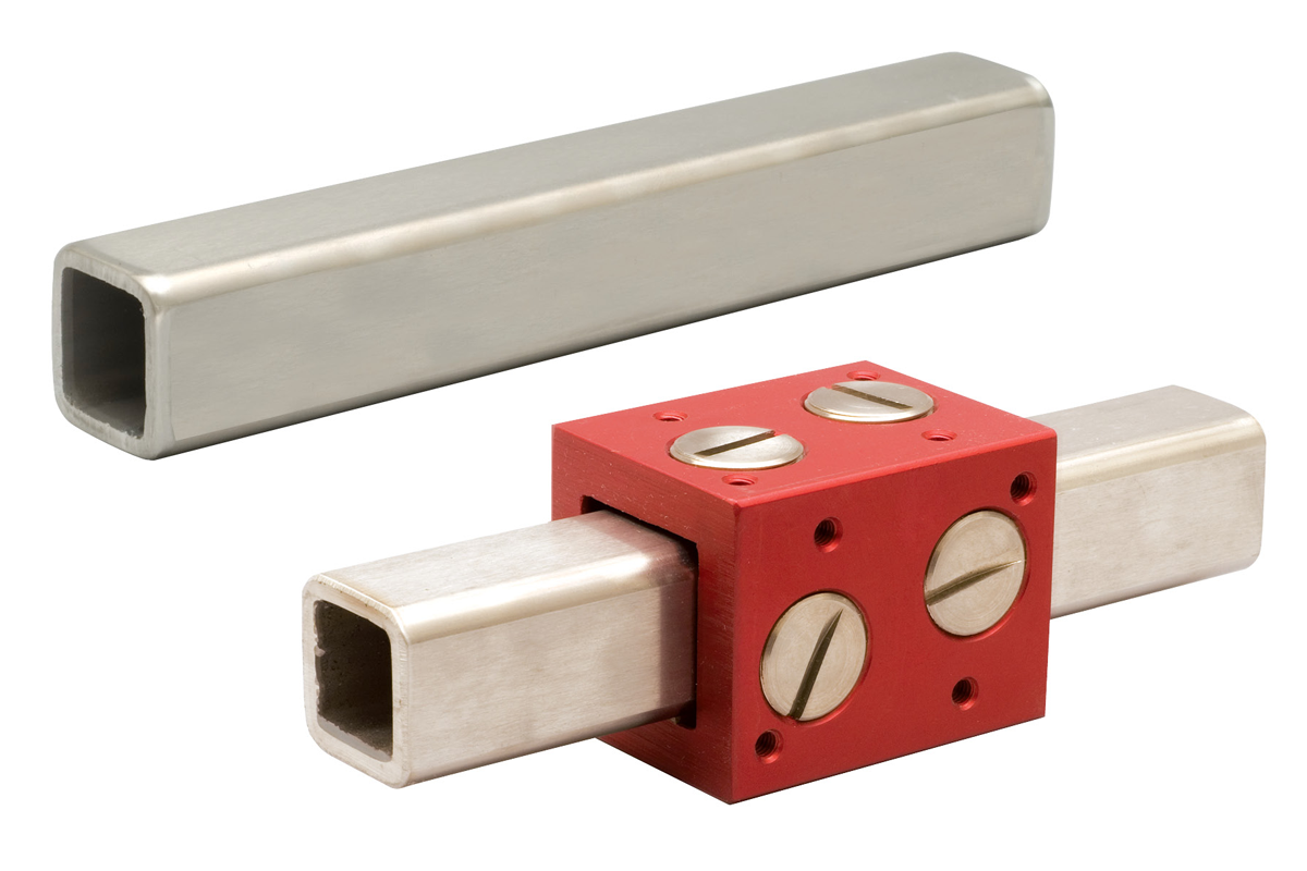
| Part No. | Description | Weight lb./in. |
|---|---|---|
| PST16-xxx.xxx | Standard 1.0" 304 stainless steel square shafting. | 0.12 |
| PST24-xxx.xxx | Standard 1.5" 304 stainless steel square shafting. | 0.18 |
Note: Specify length in part number using inches. Example: for 1.0" shafting total length 15" = PST16-015.000.
Mounting Accessories
All mounting accessories are made from cast 356-T6 aluminum for good strength and corrosion resistance.
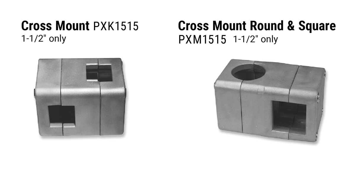
Square Clamp PFL
Specify length in inches
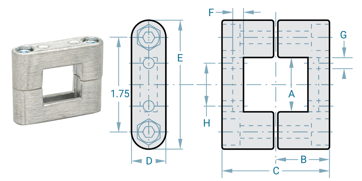
| Part No. | A | B | C | D | E | F | G | H |
|---|---|---|---|---|---|---|---|---|
| PFL1000 | 1.00 | 0.984 | 1.968 | 0.630 | 2.362 | 0.197 | 0.200 | 0.787 |
| PFL1500 | 1.50 | 1.338 | 2.677 | 0.787 | 2.953 | 0.276 | 0.256 | 1.024 |
Flange Base
PBH1000
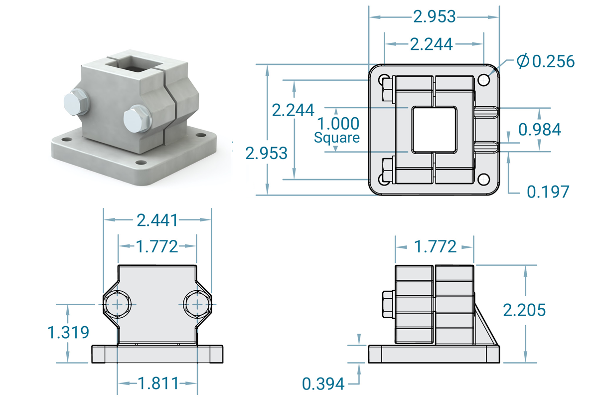
Flange Base
PBH1500
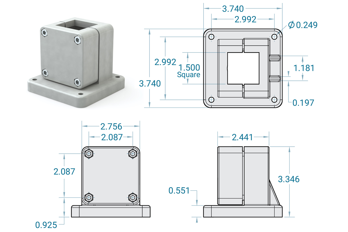
Simplicity Metric Linear Plain Bearings
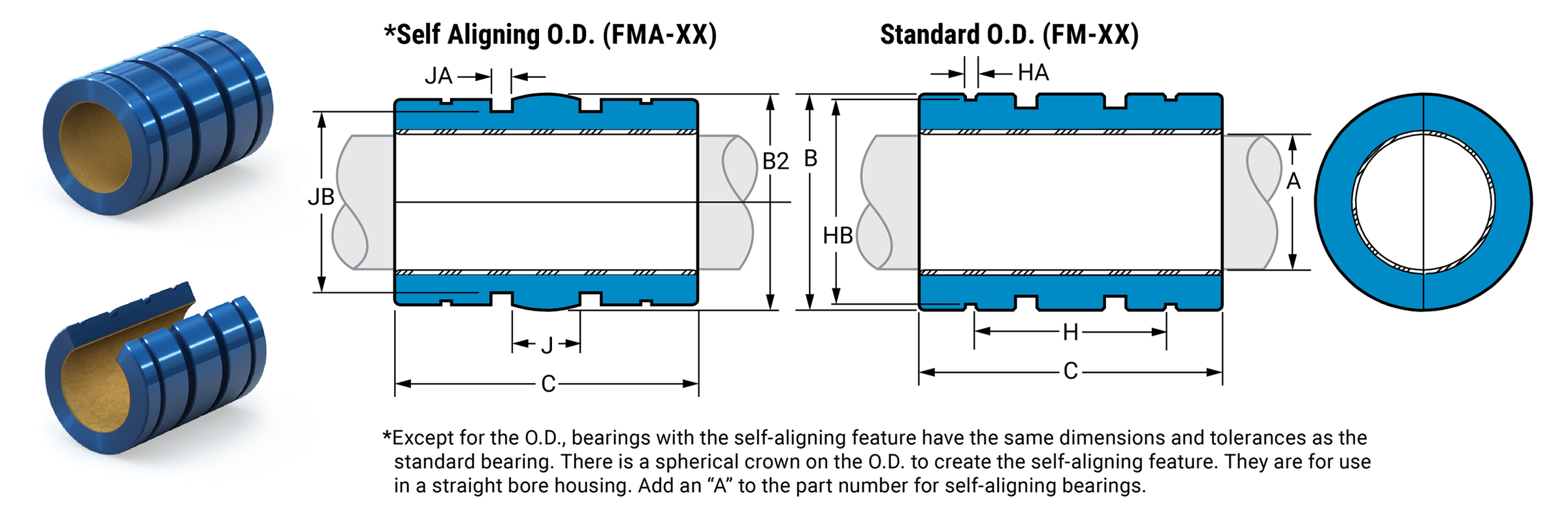
Dimensional Information
| Precision I.D. Series Similar to Preloaded Ball Bearing |
Compensated I.D. Series Similar to Standard Ball Bearing |
B Standard O.D. H7 |
B2 Self-Aligning O.D. FMA |
C Length |
Concentric | Bearing Weight |
||||||||||
|---|---|---|---|---|---|---|---|---|---|---|---|---|---|---|---|---|
| Part No. | Nominal Size |
A Bearing I.D. F8 |
Part No. | A Bearing I.D. |
||||||||||||
| Closed | Open | mm | Min. | Max. | Closed | Open | Min. | Max. | Min. | Max. | Min. | Max. | Min. | Max. | Max. mm | Kg. |
| FM05 | FMN05 | 5 | 5.010 | 5.028 | FMC05 | FMCN05 | 5.060 | 5.078 | 11.982 | 12 | 11.941 | 11.966 | 21.619 | 22 | 0.0254 | 0.004 |
| FM08 | FMN08 | 8 | 8.013 | 8.035 | FMC08 | FMCN08 | 8.063 | 8.085 | 15.982 | 16 | 15.941 | 15.966 | 24.619 | 25 | 0.0254 | 0.009 |
| FM10 | FMN10 | 10 | 10.013 | 10.035 | FMC10 | FMCN10 | 10.063 | 10.085 | 18.979 | 19 | 18.938 | 18.964 | 28.619 | 29 | 0.0254 | 0.014 |
| FM12 | FMN12 | 12 | 12.016 | 12.043 | FMC12 | FMCN12 | 12.066 | 12.093 | 21.979 | 22 | 21.938 | 21.963 | 31.619 | 32 | 0.0254 | 0.017 |
| FM16 | FMN16 | 16 | 16.016 | 16.043 | FMC16 | FMCN16 | 16.066 | 16.093 | 25.979 | 26 | 25.938 | 25.964 | 35.619 | 36 | 0.0254 | 0.028 |
| FM20 | FMN20 | 20 | 20.020 | 20.053 | FMC20 | FMCN20 | 20.096 | 20.129 | 31.975 | 32 | 31.938 | 31.963 | 44.619 | 45 | 0.0254 | 0.054 |
| FM25 | FMN25 | 25 | 25.020 | 25.053 | FMC25 | FMCN25 | 25.096 | 25.129 | 39.975 | 40 | 39.936 | 39.962 | 57.619 | 58 | 0.0254 | 0.109 |
| FM30 | FMN30 | 30 | 30.020 | 30.053 | FMC30 | FMCN30 | 30.096 | 30.129 | 46.975 | 47 | 46.937 | 46.962 | 67.619 | 68 | 0.0254 | 0.176 |
| FM40 | FMN40 | 40 | 40.025 | 40.064 | FMC40 | FMCN40 | 40.127 | 40.166 | 61.970 | 62 | 61.935 | 61.961 | 79.619 | 80 | 0.0254 | 0.356 |
| FM50 | FMN50 | 50 | 50.025 | 50.064 | FMC50 | FMCN50 | 50.127 | 50.166 | 74.970 | 75 | 74.935 | 74.960 | 99.619 | 100 | 0.0254 | 0.628 |
| FM60 | FMN60 | 60 | 60.030 | 60.076 | FMC60 | FMCN60 | 60.182 | 60.228 | 89.965 | 90 | 89.931 | 89.957 | 124.619 | 125 | 0.0380 | 1.117 |
| FM80 | FMN80 | 80 | 80.030 | 80.076 | FMC80 | FMCN80 | 80.182 | 80.228 | 119.965 | 120 | 119.931 | 119.957 | 164.619 | 165 | 0.0510 | 2.679 |
Mounting Dimensions
| Part No. | Nominal Size mm |
H Between Ret. Rings |
HA Ret. Rings GRV. Width |
HB Ret. Rings GRV. Dia. |
Ret. Ring Part No. Din 471 |
J Between O'ring GRVS. |
JA O'ring GRV. Width |
JB O'ring GRV. Dia. |
Metric O'ring Size | |
|---|---|---|---|---|---|---|---|---|---|---|
| Closed | Open | |||||||||
| FM05 | FMN05 | 5 | 12 | 1.14 | 11.5 | 12 | 5 | 2 | 9.86 | 9.7 x 1.3 |
| FM08 | FMN08 | 8 | 14 | 1.14 | 15.2 | 16 | 5.33 | 2 | 13.2 | 13 x 1.7 |
| FM10 | FMN10 | 10 | 19.4 | 1.32 | 18.0 | 19 | 5.63 | 2.44 | 15.7 | 15.5 x 2 |
| FM12 | FMN12 | 12 | 20 | 1.32 | 21.0 | 22 | 6 | 3.17 | 17.9 | 17.5 x 2.5 |
| FM16 | FMN16 | 16 | 22 | 1.32 | 24.9 | 26 | 8 | 3.17 | 21.9 | 21.5 x 2.5 |
| FM20 | FMN20 | 20 | 28 | 1.63 | 30.3 | 32 | 10 | 3.17 | 27.9 | 27.5 x 2.5 |
| FM25 | FMN25 | 25 | 40 | 1.90 | 37.5 | 40 | 12.5 | 3.17 | 35.9 | 35.5 x 2.5 |
| FM30 | FMN30 | 30 | 48 | 1.90 | 44.5 | 47 | 15 | 3.17 | 42.7 | 42.52 x 2.62 |
| FM40 | FMN40 | 40 | 56 | 2.20 | 59.0 | 62 | 20 | 4.1 | 56.3 | 56 x 3.5 |
| FM50 | FMN50 | 50 | 72 | 2.70 | 72.0 | 75 | 25 | 4.1 | 69.2 | 69 x 3.5 |
| FM60 | FMN60 | 60 | 95 | 3.20 | 86.4 | 90 | 30 | 7.1 | 81.7 | 81 x 5 |
| FM80 | FMN80 | 80 | 125 | 4.17 | 116.1 | 120 | 40 | 7.1 | 111.7 | 111 x 5 |
Linear Plain Bearings FMN
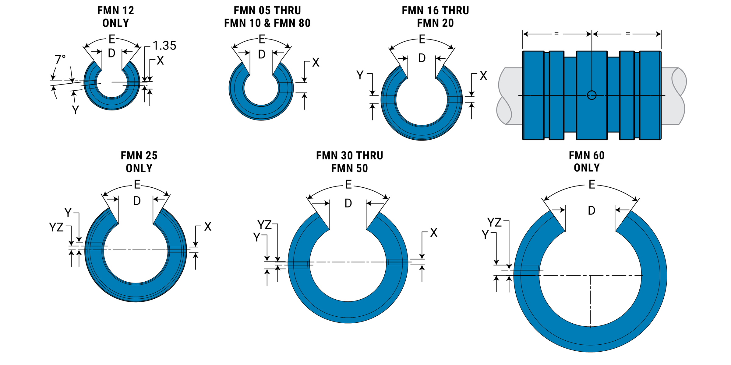
Open Dimensional Information
| Part No. | Nominal Size mm |
D Slot Wide Min. |
E Slot Angle |
X Ret. Hole Dia. |
Y Ret. Hole Dia. |
Yz Ret Hole Locate |
Bearing Wt. kg. |
|---|---|---|---|---|---|---|---|
| FMN05 | 5 | 3.2 | 60 | 2.2 | N/A | N/A | 0.0034 |
| FMN08 | 8 | 5.1 | 60 | 3.0 | N/A | N/A | 0.0077 |
| FMN10 | 10 | 6.4 | 60 | 3.0 | N/A | N/A | 0.0119 |
| FMN12 | 12 | 7.6 | 78 | 3.0 | 3.0 | 7.0 | 0.0156 |
| FMN16 | 16 | 10.4 | 78 | 2.2 | 3.0 | 0 | 0.0213 |
| FMN20 | 20 | 10.8 | 60 | 2.2 | 3.0 | 0 | 0.0439 |
| FMN25 | 25 | 13.2 | 60 | 3.0 | 3.0 | 1.5 | 0.0893 |
| FMN30 | 30 | 14.2 | 72 | 3.0 | 3.0 | 2.0 | 0.1460 |
| FMN40 | 40 | 19.5 | 72 | 3.0 | 3.0 | 1.5 | 0.2948 |
| FMN50 | 50 | 24.0 | 72 | 3.0 | 5.0 | 2.5 | 0.5202 |
| FMN60 | 60 | 29.6 | 72 | N/A | 6.0 | 0 | 0.9199 |
| FMN80 | 80 | 39.0 | 72 | N/A | 8.0 | 0 | 2.2269 |
Load & Speed Data
| Part No. | Effective Surface Area sq. in. |
MAX Static Load lb. Frelon® |
Effective Surface Area CM2 |
MAX Static Load N Frelon® |
||
|---|---|---|---|---|---|---|
| Gold | J | Gold | J & W | |||
| FMN05 | 0.171 | 511 | 256 | 1.10 | 2276 | 1138 |
| FMN08 | 0.310 | 926 | 463 | 2.00 | 4120 | 2060 |
| FMN10 | 0.450 | 1345 | 672 | 2.90 | 5984 | 2992 |
| FMN12 | 0.589 | 1777 | 888 | 3.80 | 7907 | 3953 |
| FMN16 | 0.899 | 2667 | 1334 | 5.80 | 11870 | 5935 |
| FMN20 | 1.395 | 4167 | 2083 | 9.00 | 18541 | 9270 |
| FMN25 | 2.248 | 6715 | 3358 | 14.50 | 29881 | 14941 |
| FMN30 | 3.162 | 9444 | 4722 | 20.40 | 42026 | 21013 |
| FMN40 | 4.960 | 14814 | 7407 | 32.00 | 65923 | 32962 |
| FMN50 | 7.750 | 23147 | 11574 | 50.00 | 103005 | 51503 |
| FMN60 | 11.625 | 34721 | 17360 | 75.00 | 154508 | 77254 |
| FMN80 | 20.460 | 61120 | 30554 | 132.00 | 271933 | 135967 |
MAX PV (m/min. * kg/sq. cm)
FrelonGOLD® = 430 PV
Frelon J = 215 PV
MAX Speed Running Dry (m/min.)
FrelonGOLD = 91.4
Frelon J = 42.6
MAX Speed Running with Lubrication (m/min.)
FrelonGOLD = 251.5
Frelon J = 122
MAX PV (m/s * N/mm2)
FrelonGOLD = 0.70 PV
Frelon J = 0.35 PV
MAX Speed Running Dry (m/s)
FrelonGOLD = 1.52
Frelon J = 0.71
MAX Speed Running with Lubrication (m/s)
FrelonGOLD = 4.19
Frelon J = 2.03
⚠ Only certified Simplicity 60 Plus Shafting provides maximum bearing performance.
Simplicity Metric Thin Wall Bearings
Plain Bearings – Compact Thin Wall FG
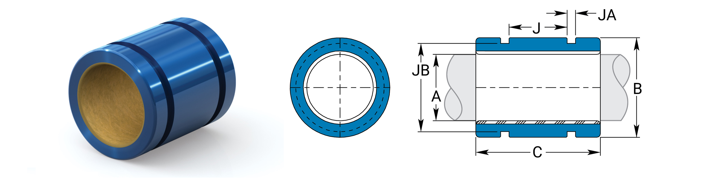
Dimensional Information
| Precision I.D. Series Similar to Preloaded Ball Bearing |
Compensated I.D. Series Similar to Standard Ball Bearing |
B O.D. H7 |
C Length |
Concentric | Bearing Weight |
|||||||
|---|---|---|---|---|---|---|---|---|---|---|---|---|
| Part No | Nominal Size |
A Bearing I.D. F8 |
Part No. | A Bearing I.D. |
||||||||
| Closed | mm | MIN | MAX | Closed | MIN | MAX | MIN | MAX | MIN | MAX | MAX mm | Kg. |
| FG06 | 6 | 6.010 | 6.028 | FGC06 | 6.060 | 6.078 | 11.98 | 12 | 17.619 | 18 | 0.0254 | 0.004 |
| FG08 | 8 | 8.013 | 8.035 | FGC08 | 8.063 | 8.085 | 14.98 | 15 | 19.619 | 20 | 0.0254 | 0.006 |
| FG10 | 10 | 10.013 | 10.035 | FGC10 | 10.063 | 10.085 | 16.98 | 17 | 21.619 | 22 | 0.0254 | 0.008 |
| FG12 | 12 | 12.016 | 12.043 | FGC12 | 12.066 | 12.093 | 21.98 | 22 | 26.619 | 27 | 0.0254 | 0.018 |
| FG15 | 15 | 15.016 | 15.043 | FGC15 | 15.066 | 15.093 | 24.98 | 25 | 27.619 | 28 | 0.0254 | 0.022 |
| FG16 | 16 | 16.016 | 16.043 | FGC16 | 16.066 | 16.093 | 25.98 | 26 | 29.619 | 30 | 0.0254 | 0.025 |
| FG18 | 18 | 18.020 | 18.053 | FGC18 | 18.096 | 18.129 | 27.98 | 28 | 29.619 | 30 | 0.0254 | 0.027 |
| FG20 | 20 | 20.020 | 20.053 | FGC20 | 20.096 | 20.129 | 31.98 | 32 | 34.619 | 35 | 0.0254 | 0.044 |
| FG25 | 25 | 25.020 | 25.053 | FGC25 | 25.096 | 25.129 | 39.98 | 40 | 44.619 | 45 | 0.0254 | 0.091 |
| FG30 | 30 | 30.020 | 30.053 | FGC30 | 30.096 | 30.129 | 44.98 | 45 | 53.619 | 54 | 0.0254 | 0.127 |
| FG35 | 35 | 35.025 | 35.064 | FGC35 | 35.127 | 35.166 | 51.98 | 52 | 61.619 | 62 | 0.0254 | 0.189 |
| FG40 | 40 | 40.025 | 40.064 | FGC40 | 40.127 | 40.166 | 59.98 | 60 | 71.619 | 72 | 0.0254 | 0.301 |
| FG50 | 50 | 50.025 | 50.064 | FGC50 | 50.127 | 50.166 | 74.98 | 75 | 89.619 | 90 | 0.0254 | 0.596 |
Mounting Dimensions
| Part No. | Nominal Size | J Between O-Ring GRVS. |
JA O-Ring GRV. Width |
JB O-Ring GRV. Dia. |
O-Ring Size | O-Ring Part Number | |
|---|---|---|---|---|---|---|---|
| Precision | Compensated | ||||||
| FG06 | FGC06 | 6 | N/A | N/A | N/A | N/A | N/A |
| FG08 | FGC08 | 8 | 8.0 | 2.032 | 12.201 | 12 x 1.7 | 6000025 |
| FG10 | FGC10 | 10 | 8.3 | 2.032 | 14.415 | 14 x 1.6 | 6000026 |
| FG12 | FGC12 | 12 | 12.0 | 3.175 | 17.907 | 17.5 x 2.5 | 6000016 |
| FG15 | FGC15 | 15 | 12.7 | 3.175 | 20.671 | 20 x 2.65 | 6000029 |
| FG16 | FGC16 | 16 | 12.7 | 3.175 | 21.882 | 21.5 x 2.5 | 6000017 |
| FG18 | FGC08 | 18 | 14.0 | 3.175 | 23.885 | 23.5 x 2.5 | 6000031 |
| FG20 | FGC20 | 20 | 17.0 | 3.175 | 27.864 | 27.5 x 2.5 | 6000018 |
| FG25 | FGC25 | 25 | 24.0 | 3.175 | 35.865 | 35.5 x 2.5 | 6000019 |
| FG30 | FGC30 | 30 | 30.0 | 3.175 | 40.895 | 40 x 2.5 | 6000034 |
| FG35 | FGC35 | 35 | 36.0 | 4.115 | 46.200 | 46 x 3.5 | 6000035 |
| FG40 | FGC40 | 40 | 37.3 | 4.115 | 54.255 | 53 x 3.5 | 6000036 |
| FG50 | FGC50 | 50 | 50 | 4.115 | 69.215 | 69 x 3.5 | 6000022 |
Load & Speed Data
| Part No. | Effective Surface Area CM2 |
Max Static Load lb. Frelon® |
Effective Surface Area CM2 |
MAX Static Load N Frelon® |
||
|---|---|---|---|---|---|---|
| GOLD | J & W | GOLD | J & W | |||
| FG06 | 1.1 | 498 | 249 | 1.10 | 2217 | 1109 |
| FG08 | 1.6 | 741 | 370 | 1.60 | 3296 | 1648 |
| FG10 | 2.2 | 1018 | 509 | 2.20 | 4532 | 2266 |
| FG12 | 3.2 | 1499 | 749 | 3.20 | 6671 | 3335 |
| FG15 | 4.2 | 1944 | 972 | 4.20 | 8652 | 4326 |
| FG16 | 4.8 | 2222 | 1111 | 4.80 | 9888 | 4944 |
| FG18 | 5.4 | 2500 | 1250 | 5.40 | 11125 | 5562 |
| FG20 | 7.0 | 3241 | 1620 | 7.00 | 14421 | 7210 |
| FG25 | 11.3 | 5207 | 2604 | 11.30 | 23171 | 11586 |
| FG30 | 16.2 | 7500 | 3750 | 16.20 | 33374 | 16687 |
| FG35 | 21.7 | 10048 | 5024 | 21.70 | 44714 | 22357 |
| FG40 | 28.8 | 13333 | 6666 | 28.80 | 59331 | 29665 |
| FG50 | 45.0 | 20833 | 10416 | 45.00 | 92705 | 46352 |
MAX PV (m/min. * kg/sq. cm)
FrelonGOLD® = 430 PV
Frelon J = 215 PV
MAX Speed Running Dry (m/min.)
FrelonGOLD = 91.4
Frelon J = 42.6
MAX Speed Running with Lubrication (m/min.)
FrelonGOLD = 251.5
Frelon J = 122
MAX PV (m/s * N/mm2)
FrelonGOLD = 0.70 PV
Frelon J = 0.35 PV
MAX Speed Running Dry (m/s)
FrelonGOLD = 1.52
Frelon J = 0.71
MAX Speed Running with Lubrication (m/s)
FrelonGOLD = 4.19
Frelon J = 2.03
⚠ Only certified Simplicity 60 Plus Shafting provides maximum bearing performance.
Plain Bearings – Compact Thin Wall FMT
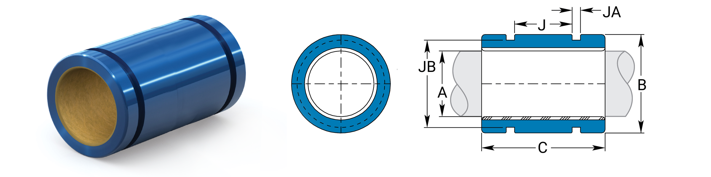
Dimensional Information
| Precision I.D. Series Similar to Preloaded Ball Bearing |
Compensated I.D. Series Similar to Standard Ball Bearing |
B O.D. H7 |
C Length |
Concentric | Bearing Weight |
|||||||
|---|---|---|---|---|---|---|---|---|---|---|---|---|
| Part No | Nominal Size |
A Bearing I.D. F8 |
Part No. | A Bearing I.D. |
||||||||
| Closed | mm | MIN | MAX | Closed | MIN | MAX | MIN | MAX | MIN | MAX | MAX mm | Kg. |
| FMT06 | 6 | 6.010 | 6.028 | FMTC06 | 6.060 | 6.078 | 11.982 | 12 | 21.619 | 22 | 0.0254 | 0.0057 |
| FMT08 | 8 | 8.013 | 8.035 | FMTC08 | 8.063 | 8.085 | 14.982 | 15 | 23.619 | 24 | 0.0254 | 0.0071 |
| FMT10 | 10 | 10.013 | 10.035 | FMTC10 | 10.063 | 10.085 | 16.982 | 17 | 25.619 | 26 | 0.0254 | 0.0085 |
| FMT12 | 12 | 12.016 | 12.043 | FMTC12 | 12.066 | 12.093 | 18.979 | 19 | 27.619 | 28 | 0.0254 | 0.0113 |
| FMT14 | 14 | 14.016 | 14.043 | FMTC14 | 14.066 | 14.093 | 20.979 | 21 | 27.619 | 28 | 0.0254 | 0.0128 |
| FMT16 | 16 | 16.016 | 16.043 | FMTC16 | 16.066 | 16.093 | 23.979 | 24 | 29.619 | 30 | 0.0254 | 0.0184 |
| FMT20 | 20 | 20.020 | 20.053 | FMTC20 | 20.096 | 20.129 | 27.979 | 28 | 29.619 | 30 | 0.0254 | 0.0227 |
| FMT25 | 25 | 25.020 | 25.053 | FMTC25 | 25.096 | 25.129 | 34.975 | 35 | 39.619 | 40 | 0.0254 | 0.0439 |
| FMT30 | 30 | 30.020 | 30.053 | FMTC30 | 30.096 | 30.129 | 39.975 | 40 | 49.619 | 50 | 0.0254 | 0.0652 |
| FMT40 | 40 | 40.025 | 40.064 | FMTC40 | 40.127 | 40.166 | 51.970 | 52 | 59.619 | 60 | 0.0254 | 0.1233 |
| FMT50 | 50 | 50.025 | 50.064 | FMTC50 | 50.127 | 50.166 | 61.970 | 62 | 69.619 | 70 | 0.0254 | 0.1772 |
Mounting Dimensions
| Part No. | Nominal Size | J Between O-Ring GRVS. |
JA O-Ring GRV. Width |
JB O-Ring GRV. Dia. |
O-Ring Size | O-Ring Part Number | |
|---|---|---|---|---|---|---|---|
| Precision | Compensated | ||||||
| FMT06 | FMTC06 | 6 | N/A | N/A | N/A | N/A | N/A |
| FMT08 | FMTC08 | 8 | 10.0 | 2.000 | 12.200 | 12 x 1.7 | 6000025 |
| FMT10 | FMTC10 | 10 | 12.0 | 2.000 | 14.400 | 14 x 1.6 | 6000026 |
| FMT12 | FMTC12 | 12 | 14.0 | 2.000 | 16.600 | 16 x 1.5 | 6000027 |
| FMT14 | FMTC14 | 14 | 14.0 | 2.000 | 18.500 | 18 x 1.5 | 6000028 |
| FMT16 | FMTC16 | 16 | 14.0 | 2.000 | 21.300 | 21.1 x 1.6 | 6000030 |
| FMT20 | FMTC20 | 20 | 14.0 | 2.000 | 25.500 | 25 x 1.5 | 6000032 |
| FMT25 | FMTC25 | 25 | 22.0 | 3.200 | 30.900 | 30.5 x 2.5 | 6000033 |
| FMT30 | FMTC30 | 30 | 30.0 | 3.200 | 35.900 | 35.5 x 2.5 | 6000019 |
| FMT40 | FMTC40 | 40 | 40.0 | 4.100 | 46.200 | 46 x 3.5 | 6000035 |
| FMT50 | FMTC50 | 50 | 50.0 | 4.100 | 56.300 | 26 x 3.5 | 6000021 |
Load & Speed Data
| Part No. | Effective Surface Area CM2 |
Max Static Load lb. Frelon® |
Effective Surface Area CM2 |
MAX Static Load N Frelon® |
||
|---|---|---|---|---|---|---|
| GOLD | J & W | GOLD | J & W | |||
| FMT06 | 0.202 | 613 | 307 | 1.3 | 2727 | 1364 |
| FMT08 | 0.295 | 891 | 445 | 1.9 | 3963 | 1982 |
| FMT10 | 0.403 | 1204 | 602 | 2.6 | 5356 | 2678 |
| FMT12 | 0.527 | 1556 | 778 | 3.4 | 6926 | 3463 |
| FMT14 | 0.605 | 1816 | 908 | 3.9 | 8083 | 4042 |
| FMT16 | 0.744 | 2222 | 1111 | 4.8 | 9888 | 4944 |
| FMT20 | 0.930 | 2778 | 1389 | 6.0 | 12361 | 6180 |
| FMT25 | 1.550 | 4629 | 2315 | 10.0 | 20601 | 10301 |
| FMT30 | 2.325 | 6944 | 3472 | 15.0 | 30902 | 15451 |
| FMT40 | 3.720 | 11111 | 5555 | 24.0 | 49442 | 24721 |
| FMT50 | 5.425 | 16203 | 8102 | 35.0 | 72104 | 36052 |
MAX PV (m/min. * kg/sq. cm)
FrelonGOLD® = 430 PV
Frelon J = 215 PV
MAX Speed Running Dry (m/min.)
FrelonGOLD = 91.4
Frelon J = 42.6
MAX Speed Running with Lubrication (m/min.)
FrelonGOLD = 251.5
Frelon J = 122
MAX PV (m/s * N/mm2)
FrelonGOLD = 0.70 PV
Frelon J = 0.35 PV
MAX Speed Running Dry (m/s)
FrelonGOLD = 1.52
Frelon J = 0.71
MAX Speed Running with Lubrication (m/s)
FrelonGOLD = 4.19
Frelon J = 2.03
⚠ Only certified Simplicity 60 Plus Shafting provides maximum bearing performance.
Simplicity Metric Closed Pillow Blocks
Plain Bearings – Closed Pillow Blocks PM
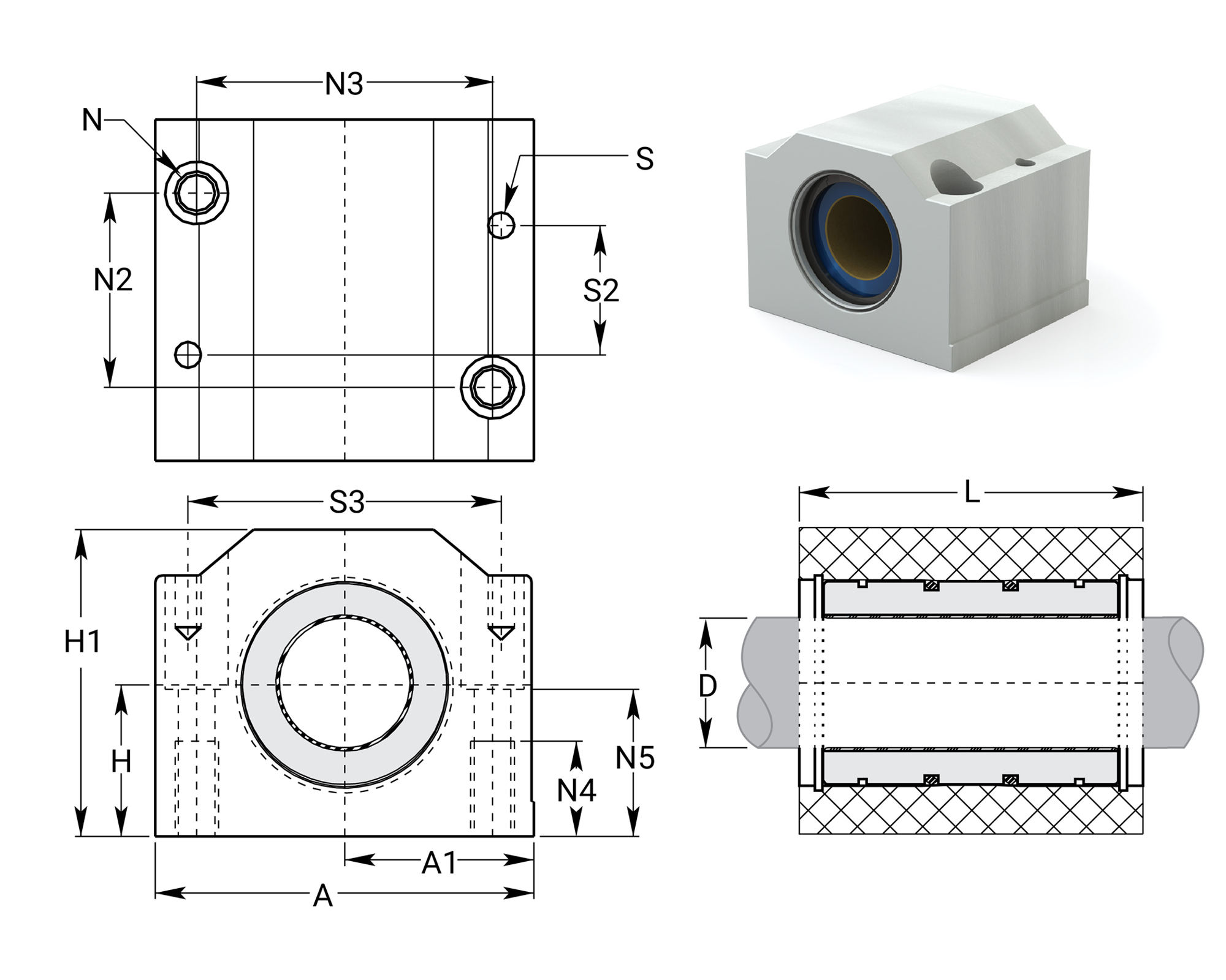
Dimensional Information
| Part No. Closed |
D Nom. Brg. I.D. mm |
H Centerline 0.015 |
H1 Height |
A Width |
A1 0.013 |
L Length |
N Bolt |
N2 | N3 | N4 | N5 | S | S2 | S3 | Max Static Load lb. Frelon® |
Max Static Load N Frelon® |
Assem. Wt. kg. |
|||
|---|---|---|---|---|---|---|---|---|---|---|---|---|---|---|---|---|---|---|---|---|
| Precision | Compensated | Gold | J & W | Gold | J & W | |||||||||||||||
| PM08 | PM08C | 8 | 15 | 28 | 35 | 17.5 | 32 | M4 x 0.7 | 20 | 25 | 9 | 14.5 | N/A | N/A | N/A | 926 | 463 | 4120 | 2060 | 0.069 |
| PM10 | PM10C | 10 | 16 | 31.5 | 40 | 20 | 36 | M5 x 0.8 | 20 | 29 | 11 | 15 | 4 | 29 | 31 | 1345 | 672 | 5984 | 2992 | 0.095 |
| PM12 | PM12C | 12 | 18 | 35 | 43 | 21.5 | 39 | M5 x 0.8 | 23 | 32 | 11 | 16.5 | 4 | 32 | 34 | 1777 | 888 | 7907 | 3953 | 0.118 |
| PM16 | PM16C | 16 | 22 | 42 | 53 | 26.5 | 43 | M6 x 1.0 | 26 | 40 | 13 | 21 | 4 | 35 | 42 | 2667 | 1334 | 11870 | 5935 | 0.200 |
| PM20 | PM20C | 20 | 25 | 50 | 59.3 | 30 | 54 | M8 x 1.25 | 32 | 45 | 18 | 24 | 5 | 45 | 50 | 4167 | 2083 | 18541 | 9270 | 0.329 |
| PM25 | PM25C | 25 | 30 | 60 | 78 | 39 | 67 | M10 x 1.5 | 40 | 60 | 22 | 29 | 6 | 20 | 64 | 6715 | 3358 | 29881 | 14941 | 0.655 |
| PM30 | PM30C | 30 | 35 | 71 | 87 | 43.5 | 79 | M10 x 1.5 | 45 | 68 | 22 | 34 | 6 | 30 | 72 | 9444 | 4722 | 42026 | 21013 | 1.020 |
| PM40 | PM40C | 40 | 45 | 91 | 108 | 54 | 91 | M12 x 1.75 | 58 | 86 | 26 | 44 | 8 | 35 | 90 | 14814 | 7407 | 65923 | 32962 | 1.846 |
| PM50 | PM50C | 50 | 50 | 105 | 132 | 66 | 113 | M16 x 2.0 | 50 | 108 | 34 | 49 | 10 | 42 | 108 | 23147 | 11574 | 103005 | 51503 | 3.169 |
Note:
(1) Standard pillow block assembly includes self-aligning housing and precision bearing.
(2) All standard metric pillow blocks use standard FM series bearings.
(3) Straight bore pillow block assembly includes standard O.D. FM series bearing in straight bore housing.
⚠ Only certified Simplicity 60 Plus Shafting provides maximum bearing performance.
Simplicity Metric Open Pillow Blocks
Plain Bearings – Open Pillow Blocks PMN
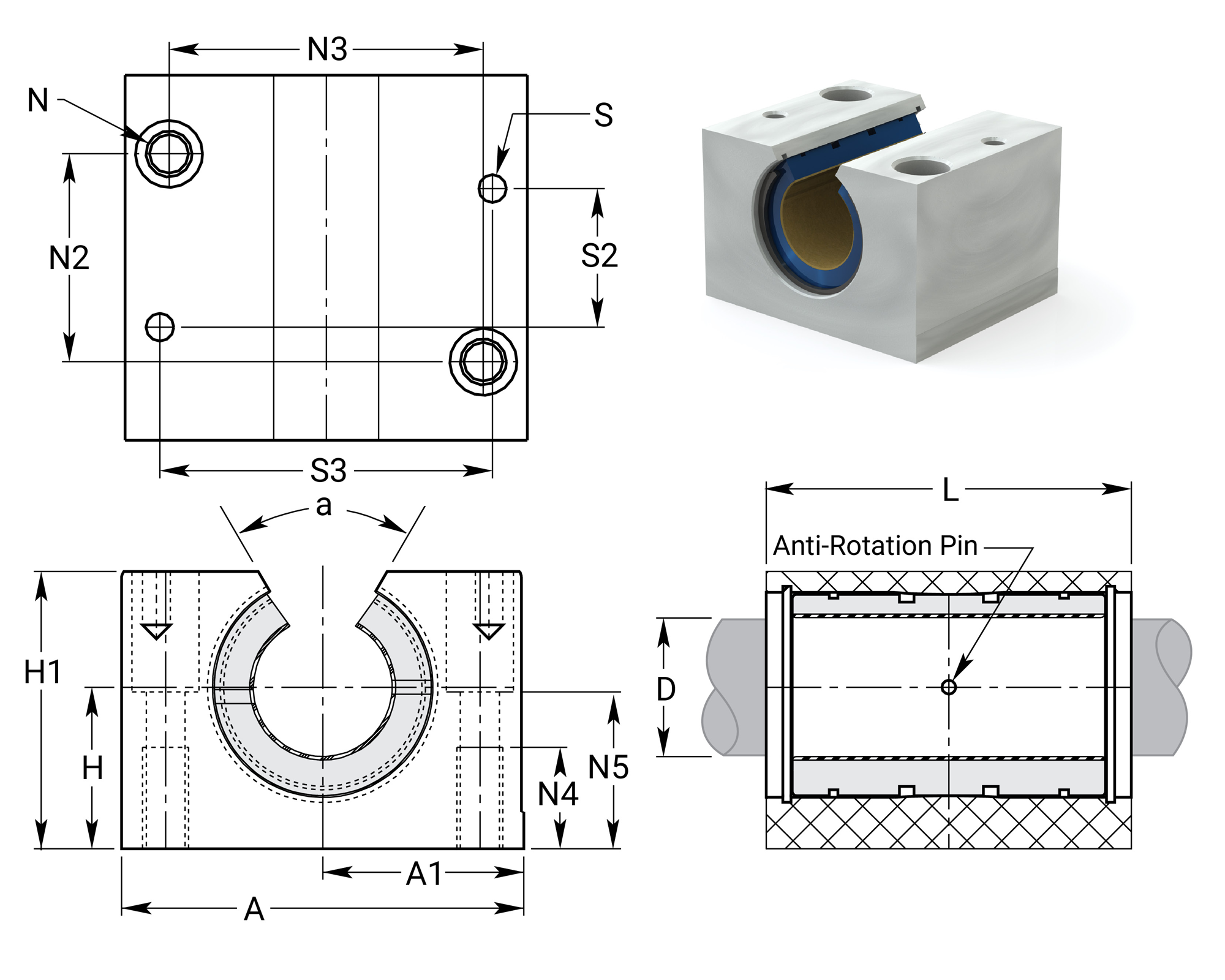
Dimensional Information
| Part No. Open |
D Nom. Brg. I.D. MIN |
H Centerline 0.015 |
H1 Height |
A Width |
A1 0.013 |
L Length |
N Bolt |
N2 | N3 | N4 | N5 | S | S2 | S3 | A mm |
Max Static Load lb. Frelon® |
Max Static Load N Frelon® |
Assem. Wt. kg. |
|||
|---|---|---|---|---|---|---|---|---|---|---|---|---|---|---|---|---|---|---|---|---|---|
| Precision | Compensated | Gold | J & W | Gold | J & W | ||||||||||||||||
| PMN12 | PMN12C | 12 | 18 | 28 | 43 | 21.5 | 39 | M5 x 0.8 | 23 | 32 | 11 | 16.5 | 4 | 32 | 34 | 66 | 1777 | 888 | 7907 | 3953 | 0.096 |
| PMN16 | PMN16C | 16 | 22 | 35 | 53 | 26.5 | 43 | M6 x 1.0 | 26 | 40 | 13 | 21 | 4 | 35 | 42 | 68 | 2667 | 1334 | 11870 | 5935 | 0.162 |
| PMN20 | PMN20C | 20 | 25 | 42 | 60 | 30 | 54 | M8 x 1.25 | 32 | 45 | 18 | 24 | 5 | 45 | 50 | 60 | 4167 | 2083 | 18541 | 9270 | 0.267 |
| PMN25 | PMN25C | 25 | 30 | 51 | 78 | 39 | 67 | M10 x 1.5 | 40 | 60 | 20 | 29 | 6 | 20 | 64 | 60 | 6715 | 3358 | 29881 | 14941 | 0.536 |
| PMN30 | PMN30C | 30 | 35 | 60 | 87 | 43.5 | 79 | M10 x 1.5 | 45 | 68 | 22 | 34 | 6 | 30 | 72 | 60 | 9444 | 4722 | 42026 | 21013 | 0.831 |
| PMN40 | PMN40C | 40 | 45 | 77 | 108 | 54 | 91 | M12 x 1.75 | 58 | 86 | 26 | 44 | 8 | 35 | 90 | 60 | 14814 | 7407 | 65923 | 32962 | 1.499 |
| PMN50 | PMN50C | 50 | 50 | 88 | 132 | 66 | 113 | M16 x 2.0 | 50 | 108 | 34 | 49 | 10 | 42 | 108 | 60 | 23147 | 11574 | 103005 | 51503 | 2.539 |
⚠ Only certified Simplicity 60 Plus Shafting provides maximum bearing performance.
Simplicity Metric Flange Bearings
Flange Bearings SFPM
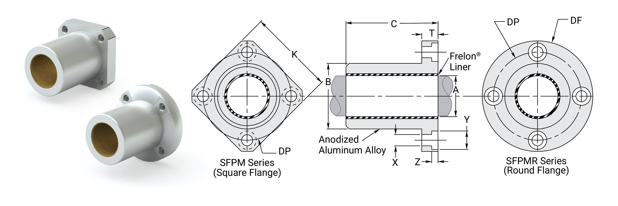
Dimensional Information
| Precision I.D. Series Similar to Preloaded Ball Bearing |
Compensated I.D. Series Similar to Standard Ball Bearing |
Nominal Size mm |
B Body O.D. H7 |
C Length H13 |
Effective Surface Area CM2 |
Max Static Load N Frelon® |
|||||||||
|---|---|---|---|---|---|---|---|---|---|---|---|---|---|---|---|
| Part No. | A Bearing I.D. F8 |
Part No. | A Bearing I.D. |
||||||||||||
| Square | Round | MIN | MAX | Square | Round | MIN | MAX | MIN | MAX | MIN | MAX | GOLD | J & W | ||
| SFPM08 | SFPMR08 | 8.013 | 8.035 | SFPM08C | SFPMR08C | 8.063 | 8.085 | 8 | 15.982 | 16 | 24.8 | 25 | 2.094 | 4316 | 2168 |
| SFPM12 | SFPMR12 | 12.016 | 12.043 | SFPM12C | SFPMR12C | 12.066 | 12.093 | 12 | 21.979 | 22 | 31.8 | 32 | 4.021 | 8280 | 4159 |
| SFPM16 | SFPMR16 | 16.016 | 16.043 | SFPM16C | SFPMR16C | 16.066 | 16.093 | 16 | 25.979 | 26 | 35.8 | 36 | 6.032 | 12429 | 6239 |
| SFPM20 | SFPMR20 | 20.020 | 20.053 | SFPM20C | SFPMR20C | 20.096 | 20.129 | 20 | 31.975 | 32 | 44.8 | 45 | 9.425 | 19414 | 9751 |
| SFPM25 | SFPMR25 | 25.020 | 25.053 | SFPM25C | SFPMR25C | 25.096 | 25.129 | 25 | 39.975 | 40 | 57.7 | 58 | 15.184 | 31284 | 15706 |
| SFPM30 | SFPMR30 | 30.020 | 30.053 | SFPM30C | SFPMR30C | 30.096 | 30.129 | 30 | 46.975 | 47 | 67.7 | 68 | 21.363 | 44008 | 22102 |
| SFPM40 | SFPMR40 | 40.025 | 40.064 | SFPM40C | SFPMR40C | 40.127 | 40.166 | 40 | 61.970 | 62 | 79.7 | 80 | 33.510 | 69033 | 34669 |
| SFPM50 | SFPMR50 | 50.025 | 50.064 | SFPM50C | SFPMR50C | 50.127 | 50.166 | 50 | 74.970 | 75 | 99.7 | 100 | 52.360 | 107871 | 54161 |
| SFPM60 | SFPMR60 | 60.030 | 60.076 | SFPM60C | SFPMR60C | 60.182 | 60.228 | 60 | 89.965 | 90 | 124.6 | 125 | 78.540 | 161796 | 81246 |
| SFPM80 | SFPMR80 | 80.030 | 80.076 | SFPM80C | SFPMR80C | 80.182 | 80.228 | 80 | 119.965 | 120 | 164.6 | 165 | 138.230 | 284765 | 142991 |
Note:
(1) Formula used for effective surface area is (pi * ID * L)/3.
(2) Max static load is effective surface area times MAX load for FrelonGOLD®.
(3) - 210 kgf/cm2 is the rating for FrelonGOLD; 105.45 kgf/cm2 is the rating for Frelon J.
Mounting Dimensions
| Part No. | K Square Max. |
DF O.D. Max. |
T Length Max. |
Dp Bolt Circle | X Hole | Y C'Bore Depth | Z C'Bore Depth | Clamping Bolt | Concentricity | Squareness | SFPM Weight kg. |
SFPMR Weight kg. |
|
|---|---|---|---|---|---|---|---|---|---|---|---|---|---|
| Square | Round | ||||||||||||
| SFPM08 | SFPMR08 | 25 | 32 | 8 | 24 | 3.5 | 6 | 3.1 | M 3 | 0.012 | 0.012 | 0.018 | 0.022 |
| SFPM12 | SFPMR12 | 32 | 42 | 9 | 32 | 4.5 | 7.5 | 4.1 | M 4 | 0.012 | 0.012 | 0.037 | 0.046 |
| SFPM16 | SFPMR16 | 35 | 46 | 9 | 36 | 4.5 | 7.5 | 4.1 | M 4 | 0.012 | 0.012 | 0.047 | 0.058 |
| SFPM20 | SFPMR20 | 42 | 54 | 11 | 43 | 5.5 | 9 | 5.1 | M 5 | 0.015 | 0.015 | 0.085 | 0.101 |
| SFPM25 | SFPMR25 | 50 | 62 | 11 | 51 | 5.5 | 9 | 5.1 | M 5 | 0.015 | 0.015 | 0.156 | 0.172 |
| SFPM30 | SFPMR30 | 60 | 76 | 14 | 62 | 6.6 | 11 | 6.1 | M 6 | 0.015 | 0.015 | 0.257 | 0.293 |
| SFPM40 | SFPMR40 | 75 | 98 | 18 | 80 | 9.0 | 14 | 8.1 | M 8 | 0.017 | 0.017 | 0.500 | 0.595 |
| SFPM50 | SFPMR50 | 88 | 112 | 18 | 94 | 9.0 | 14 | 8.1 | M 8 | 0.017 | 0.017 | 0.825 | 0.930 |
| SFPM60 | SFPMR60 | 106 | 134 | 24 | 112 | 11.0 | 17 | 11.1 | M 10 | 0.020 | 0.020 | 1.506 | 1.697 |
| SFPM80 | SFPMR80 | 136 | 164 | 24 | 142 | 11.0 | 17 | 11.1 | M 10 | 0.020 | 0.020 | 3.308 | 3.483 |
Double Flange Bearings DFPM
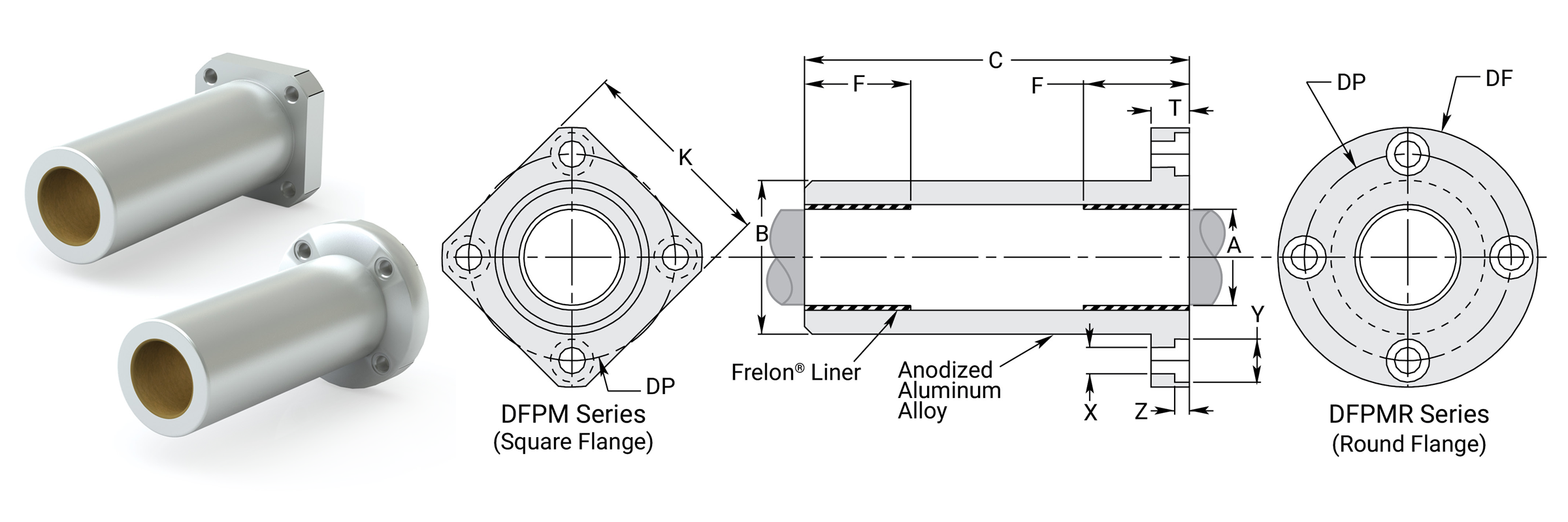
Dimensional Information
| Precision I.D. Series Similar to Preloaded Ball Bearing |
Compensated I.D. Series Similar to Standard Ball Bearing |
Nominal Size mm |
B Body O.D. H7 |
C Length |
F Length Each End |
Effective Surface Area CM2 |
Max Static Load N Frelon® |
|||||||||
|---|---|---|---|---|---|---|---|---|---|---|---|---|---|---|---|---|
| Part No. | A Bearing I.D. F8 |
Part No. | A Bearing I.D. |
|||||||||||||
| Square | Round | MIN | MAX | Square | Round | MIN | MAX | MIN | MAX | MIN | MAX | GOLD | J & W | |||
| DFPM08 | DFPMR08 | 8.013 | 8.035 | DFPM08C | DFPMR08C | 8.063 | 8.085 | 8 | 15.982 | 16 | 44.7 | 45 | 12.1 | 2.027 | 4179 | 2099 |
| DFPM12 | DFPMR12 | 12.016 | 12.043 | DFPM12C | DFPMR12C | 12.066 | 12.093 | 12 | 21.979 | 22 | 56.7 | 57 | 15.4 | 3.870 | 7976 | 4002 |
| DFPM16 | DFPMR16 | 16.016 | 16.043 | DFPM16C | DFPMR16C | 16.066 | 16.093 | 16 | 25.979 | 26 | 69.7 | 70 | 20.4 | 6.836 | 14087 | 7073 |
| DFPM20 | DFPMR20 | 20.020 | 20.053 | DFPM20C | DFPMR20C | 20.096 | 20.129 | 20 | 31.975 | 32 | 79.7 | 80 | 22.1 | 9.257 | 19071 | 9575 |
| DFPM25 | DFPMR25 | 25.020 | 25.053 | DFPM25C | DFPMR25C | 25.096 | 25.129 | 25 | 39.975 | 40 | 111.6 | 112 | 33.1 | 17.331 | 35708 | 17933 |
| DFPM30 | DFPMR30 | 30.020 | 30.053 | DFPM30C | DFPMR30C | 30.096 | 30.129 | 30 | 46.975 | 47 | 122.6 | 123 | 35 | 21.991 | 45303 | 22749 |
| DFPM40 | DFPMR40 | 40.025 | 40.064 | DFPM40C | DFPMR40C | 40.127 | 40.166 | 40 | 61.970 | 62 | 150.6 | 151 | 44 | 36.861 | 75939 | 38131 |
| DFPM50 | DFPMR50 | 50.025 | 50.064 | DFPM50C | DFPMR50C | 50.127 | 50.166 | 50 | 74.970 | 75 | 191.6 | 192 | 69.5 | 72.780 | 149936 | 75282 |
| DFPM60 | DFPMR60 | 60.030 | 60.076 | DFPM60C | DFPMR60C | 60.182 | 60.228 | 60 | 89.965 | 90 | 208.6 | 209 | 73 | 91.735 | 188980 | 94892 |
Note:
(1) Formula used for effective surface area is (pi * ID * L)/3.
(2) MAX static load is effective surface area times MAX load for FrelonGOLD®.
(3) - 210 kgf/cm2 is the rating for FrelonGOLD®; 105.45 kgf/cm2 is the rating for Frelon J.
(4) Frelon pads in each end (F dimension).
Mounting Dimensions
| Part No. | K Square Max. |
DF O.D. Max. |
T Length Max. |
Dp Bolt Circle | X Hole | Y C'Bore Depth | Z C'Bore Depth | Clamping Bolt | Concentricity | Squareness | DFPM Weight kg. |
DFPMR Weight kg. |
|
|---|---|---|---|---|---|---|---|---|---|---|---|---|---|
| Square | Round | ||||||||||||
| DFPM08 | DFPMR08 | 25 | 32 | 8 | 24 | 3.5 | 6 | 3.1 | M 3 | 0.015 | 0.015 | 0.027 | 0.031 |
| DFPM12 | DFPMR12 | 32 | 42 | 9 | 32 | 4.5 | 7.5 | 4.1 | M 4 | 0.015 | 0.015 | 0.055 | 0.064 |
| DFPM16 | DFPMR16 | 35 | 46 | 9 | 36 | 4.5 | 7.5 | 4.1 | M 4 | 0.015 | 0.015 | 0.078 | 0.089 |
| DFPM20 | DFPMR20 | 42 | 54 | 11 | 43 | 5.5 | 9 | 5.1 | M 5 | 0.017 | 0.017 | 0.133 | 0.149 |
| DFPM25 | DFPMR25 | 50 | 62 | 11 | 51 | 5.5 | 9 | 5.1 | M 5 | 0.017 | 0.017 | 0.270 | 0.286 |
| DFPM30 | DFPMR30 | 60 | 76 | 14 | 62 | 6.6 | 11 | 6.1 | M 6 | 0.017 | 0.017 | 0.413 | 0.450 |
| DFPM40 | DFPMR40 | 75 | 98 | 18 | 80 | 9.0 | 14 | 8.1 | M 8 | 0.020 | 0.020 | 0.846 | 0.942 |
| DFPM50 | DFPMR50 | 88 | 112 | 18 | 94 | 9.0 | 14 | 8.1 | M 8 | 0.020 | 0.020 | 1.450 | 1.556 |
| DFPM60 | DFPMR60 | 106 | 134 | 24 | 112 | 11.0 | 17 | 11.1 | M 10 | 0.025 | 0.025 | 2.329 | 2.519 |
Center Flange Bearings CFPM
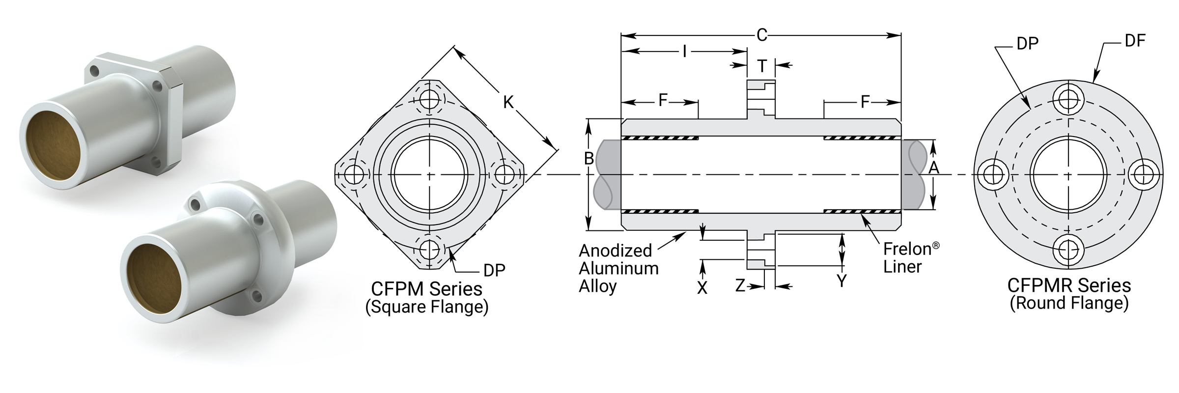
Dimensional Information
| Precision I.D. Series Similar to Preloaded Ball Bearing |
Compensated I.D. Series Similar to Standard Ball Bearing |
Nominal Size mm |
B Body O.D. H7 |
C Length |
I Length to Flng. |
F Length Each End |
Effective Surface Area CM2 |
Max Static Load N Frelon® |
|||||||||
|---|---|---|---|---|---|---|---|---|---|---|---|---|---|---|---|---|---|
| Part No. | A Bearing I.D. F8 |
Part No. | A Bearing I.D. |
||||||||||||||
| Square | Round | MIN | MAX | Square | Round | MIN | MAX | MIN | MAX | MIN | MAX | GOLD | J & W | ||||
| CFPM08 | CFPMR08 | 8.013 | 8.035 | CFPM08C | CFPMR08C | 8.063 | 8.085 | 8 | 15.982 | 16 | 45.7 | 46.3 | 19.0 | 12.1 | 2.027 | 4179 | 2099 |
| CFPM12 | CFPMR12 | 12.016 | 12.043 | CFPM12C | CFPMR12C | 12.066 | 12.093 | 12 | 21.979 | 22 | 60.7 | 61.3 | 26.0 | 15.4 | 3.870 | 7976 | 4002 |
| CFPM16 | CFPMR16 | 16.016 | 16.043 | CFPM16C | CFPMR16C | 16.066 | 16.093 | 16 | 25.979 | 26 | 67.7 | 68.3 | 29.5 | 20.4 | 6.836 | 14087 | 7073 |
| CFPM20 | CFPMR20 | 20.020 | 20.053 | CFPM20C | CFPMR20C | 20.096 | 20.129 | 20 | 31.975 | 32 | 79.7 | 80.3 | 34.5 | 22.1 | 9.257 | 19071 | 9575 |
| CFPM25 | CFPMR25 | 25.020 | 25.053 | CFPM25C | CFPMR25C | 25.096 | 25.129 | 25 | 39.975 | 40 | 111.7 | 112.3 | 50.5 | 33.1 | 17.331 | 35708 | 17933 |
| CFPM30 | CFPMR30 | 30.020 | 30.053 | CFPM30C | CFPMR30C | 30.096 | 30.129 | 30 | 46.975 | 47 | 122.7 | 123.3 | 54.5 | 35 | 21.991 | 45303 | 22749 |
| CFPM40 | CFPMR40 | 40.025 | 40.064 | CFPM40C | CFPMR40C | 40.127 | 40.166 | 40 | 61.970 | 62 | 150.7 | 151.3 | 66.5 | 44 | 36.861 | 75939 | 38131 |
| CFPM50 | CFPMR50 | 50.025 | 50.064 | CFPM50C | CFPMR50C | 50.127 | 50.166 | 50 | 74.970 | 75 | 191.7 | 192.3 | 87.0 | 69.5 | 72.780 | 149936 | 75282 |
| CFPM60 | CFPMR60 | 60.030 | 60.076 | CFPM60C | CFPMR60C | 60.182 | 60.228 | 60 | 89.965 | 90 | 208.7 | 209.3 | 92.5 | 73 | 91.735 | 188980 | 94892 |
Note:
(1) Formula used for effective surface area is (pi * ID * L)/3.
(2) MAX static load is effective surface area times MAX load for FrelonGOLD®.
(3) - 210 kgf/cm2 is the rating for FrelonGOLD®; 105.45 kgf/cm2 is the rating for Frelon J.
(4) Frelon pads in each end (F dimension).
Mounting Dimensions
| Part No. | K Square Max. |
DF O.D. Max. |
T Length Max. |
Dp Bolt Circle | X Hole | Y C'Bore Depth | Z C'Bore Depth | Clamping Bolt | Concentricity | Squareness | CFPM Weight kg. |
CFPMR Weight kg. |
|
|---|---|---|---|---|---|---|---|---|---|---|---|---|---|
| Square | Round | ||||||||||||
| CFPM08 | CFPMR08 | 25 | 32 | 8 | 24 | 3.5 | 6 | 3.1 | M 3 | 0.015 | 0.015 | 0.027 | 0.031 |
| CFPM12 | CFPMR12 | 32 | 42 | 9 | 32 | 4.5 | 7.5 | 4.1 | M 4 | 0.015 | 0.015 | 0.058 | 0.067 |
| CFPM16 | CFPMR16 | 35 | 46 | 9 | 36 | 4.5 | 7.5 | 4.1 | M 4 | 0.015 | 0.015 | 0.077 | 0.088 |
| CFPM20 | CFPMR20 | 42 | 54 | 11 | 43 | 5.5 | 9 | 5.1 | M 5 | 0.017 | 0.017 | 0.133 | 0.149 |
| CFPM25 | CFPMR25 | 50 | 62 | 11 | 51 | 5.5 | 9 | 5.1 | M 5 | 0.017 | 0.017 | 0.270 | 0.286 |
| CFPM30 | CFPMR30 | 60 | 76 | 14 | 62 | 6.6 | 11 | 6.1 | M 6 | 0.017 | 0.017 | 0.413 | 0.450 |
| CFPM40 | CFPMR40 | 75 | 98 | 18 | 80 | 9.0 | 14 | 8.1 | M 8 | 0.020 | 0.020 | 0.846 | 0.942 |
| CFPM50 | CFPMR50 | 88 | 112 | 18 | 94 | 9.0 | 14 | 8.1 | M 8 | 0.020 | 0.020 | 1.450 | 1.556 |
| CFPM60 | CFPMR60 | 106 | 134 | 24 | 112 | 11.0 | 17 | 11.1 | M 10 | 0.025 | 0.025 | 2.329 | 2.519 |
⚠ Only certified Simplicity 60 Plus Shafting provides maximum bearing performance.
Simplicity Metric Die Set Bushings
Die Set Bushings PACM
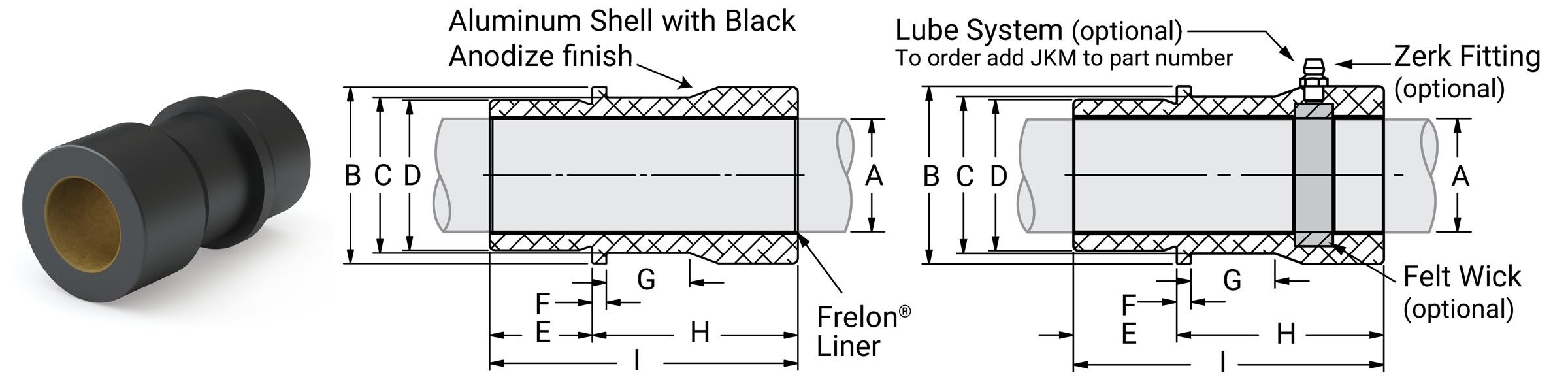
Dimensional Information
| Precision or Compensated |
Part No. | Nominal Size mm |
A Bearing I.D. |
B Flange & Barrel O.D. H7 |
C Clamp Dia. |
D Pilot O.D. H7 |
MAX | E Pilot Length |
F Flange Length |
G Recess Length |
H Head Length |
I Overall Length |
Effective Surface Area CM2 |
Max Static Load N Frelon® |
Bearing Weight Kg. |
|||
|---|---|---|---|---|---|---|---|---|---|---|---|---|---|---|---|---|---|---|
| MIN | MAX | MIN | MAX | MIN | MIN | |||||||||||||
| P C |
PACMZ19 PACMZ19C |
19 | 19.020 19.096 |
19.053 19.129 |
33.975 | 34 | 29 | 27.979 | 28 | 18 | 5 | 18 | 52 | 70 | 13.928 | 28694 | 14411 | 0.282 |
| P C |
PACMZ25 PACMZ25C |
25 | 25.020 25.096 |
25.053 25.129 |
43.975 | 44 | 39 | 37.975 | 38 | 23 | 20 | 57 | 80 | 20.944 | 43144 | 21670 | 0.551 | |
| P C |
PACMZ32 PACMZ32C |
32 | 32.020 32.096 |
32.053 32.129 |
52.970 | 53 | 48 | 44.975 | 45 | 26 | 20 | 64 | 90 | 30.159 | 62127 | 31196 | 0.834 | |
| P C |
PACMZ40 PACMZ40C |
40 | 40.025 40.127 |
40.064 40.129 |
62.970 | 63 | 58 | 53.970 | 54 | 30 | 25 | 70 | 100 | 41.888 | 86289 | 43331 | 1.229 | |
| P C |
PACMZ50 PACMZ50C |
50 | 50.025 50.127 |
50.064 50.129 |
78.970 | 79 | 74 | 64.970 | 65 | 35 | 25 | 75 | 110 | 57.596 | 118652 | 59576 | 2.055 | |
| P C |
PACMZ63 PACMZ63C |
63 | 63.020 63.128 |
63.076 63.228 |
91.965 | 92 | 87 | 80.970 | 81 | 48 | 25 | 82 | 130 | 85.765 | 106056 | 88722 | 2.984 | |
| P C |
PACMZ80 PACMZ80C |
80 | 80.030 80.182 |
80.076 80.228 |
110.965 | 111 | 106 | 99.965 | 100 | 48 | 25 | 102 | 150 | 125.664 | 258876 | 129992 | 4.772 | |
Note:
(1) Formula used for effective surface area is (pi * ID * L)/3.
(2) Shell material is aluminum..
(3) For lubrication system add JKM, example: PACMZ750JKM.
(4) MAX static load is effective surface area times max load for FrelonGOLD®.
(5) – 210 kgf/cm2 is the rating for FrelonGOLD; 105.45 kgf/cm2 is the rating for Frelon J.
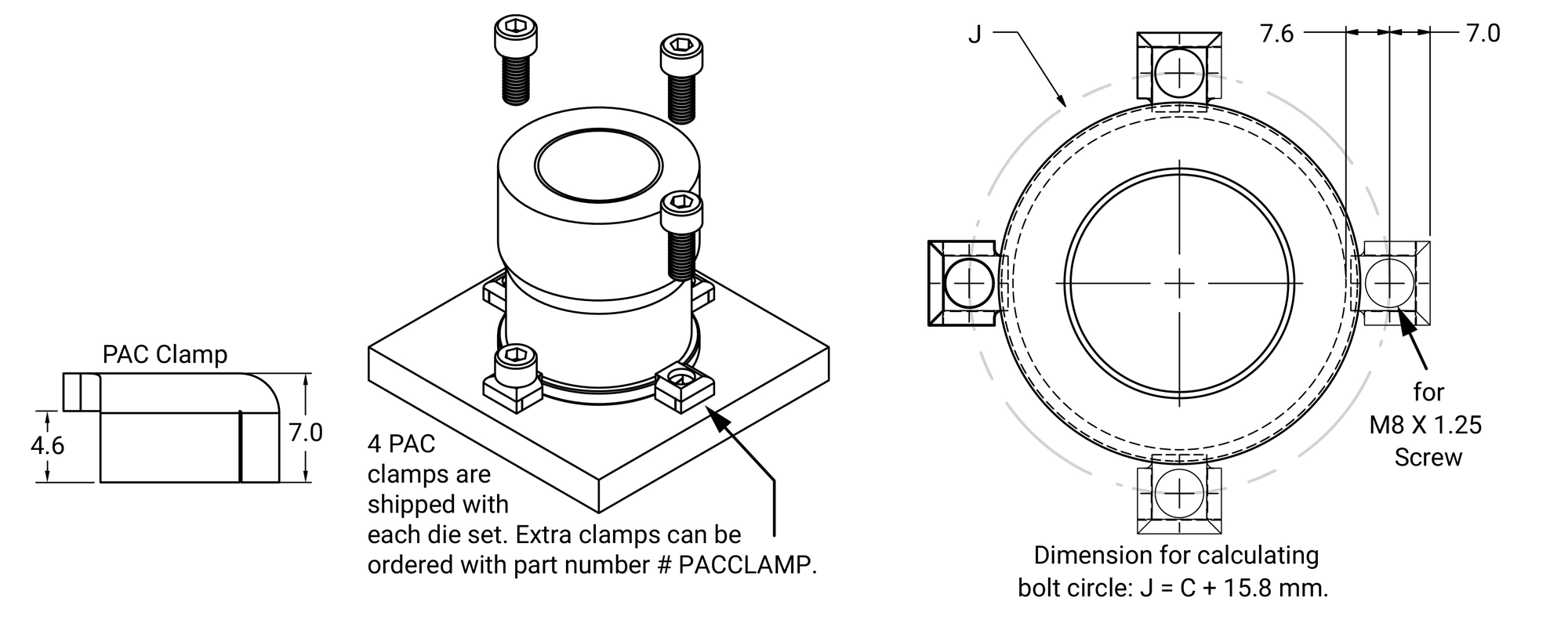
⚠ Only certified Simplicity 60 Plus Shafting provides maximum bearing performance.
Simplicity Metric Sleeve Bearings
Sleeve Bearings PSM
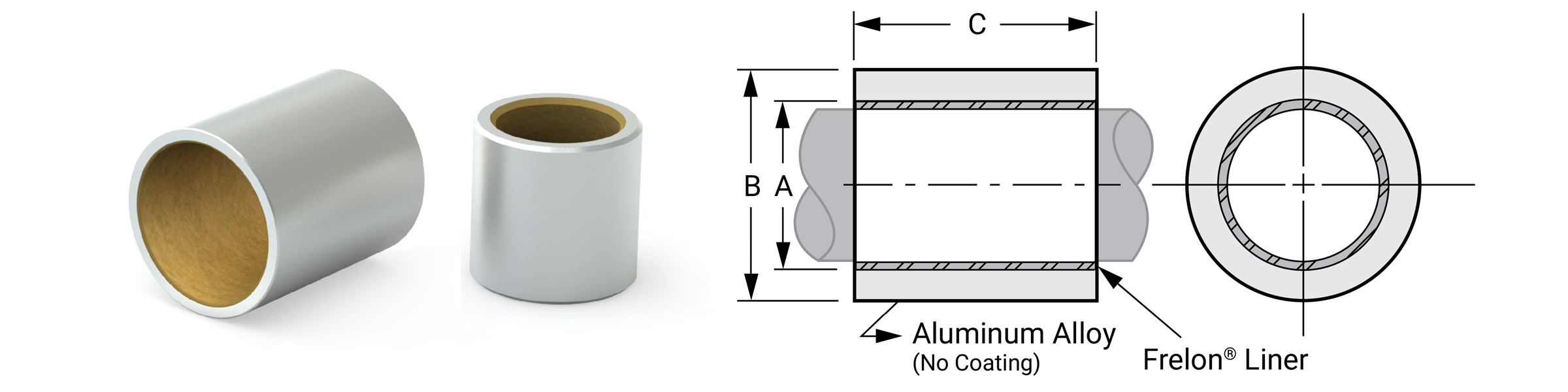
Dimensional Information
| Part No. | Nominal Bearing Size |
A Bearing I.D. |
B O.D. S7 |
C Length |
Max Static Load Kg. Frelon® |
Max Static Load N Frelon® |
Bearing Weight |
Recommended Housing Bore | ||||||||||
|---|---|---|---|---|---|---|---|---|---|---|---|---|---|---|---|---|---|---|
| Slip Fit & Epoxy | Press Fit | |||||||||||||||||
| I.D. | O.D. | Length | MIN | MAX | MIN | MAX | MIN | MAX | GOLD | J & W | GOLD | J & W | Kg | MIN | MAX | MIN | MAX | |
| PSM0610-06 | 6 | 10 | 6 | 6.028 | 6.058 | 10.023 | 10.038 | 5.75 | 6 | 76 | 38 | 745 | 373 | 0.00084 | 10.038 | 10.063 | 10.000 | 10.015 |
| PSM0610-10 | 6 | 10 | 10 | 6.028 | 6.058 | 10.023 | 10.038 | 9.75 | 10 | 126 | 63 | 1236 | 618 | 0.00140 | 10.038 | 10.063 | 10.000 | 10.015 |
| PSM0812-08 | 8 | 12 | 8 | 8.033 | 8.066 | 12.028 | 12.046 | 7.75 | 8 | 134 | 67 | 1314 | 657 | 0.00140 | 12.046 | 12.071 | 12.000 | 12.018 |
| PSM0812-12 | 8 | 12 | 12 | 8.033 | 8.066 | 12.028 | 12.046 | 11.75 | 12 | 202 | 101 | 1981 | 990 | 0.00210 | 12.046 | 12.071 | 12.000 | 12.018 |
| PSM0814-08 | 8 | 14 | 8 | 8.033 | 8.066 | 14.028 | 14.046 | 7.75 | 8 | 134 | 67 | 1314 | 657 | 0.00231 | 14.046 | 14.071 | 14.000 | 14.018 |
| PSM0814-12 | 8 | 14 | 12 | 8.033 | 8.066 | 14.028 | 14.046 | 11.75 | 12 | 202 | 101 | 1981 | 990 | 0.00347 | 14.046 | 14.071 | 14.000 | 14.018 |
| PSM1014-10 | 10 | 14 | 10 | 10.033 | 10.066 | 14.028 | 14.046 | 9.75 | 10 | 210 | 105 | 2059 | 1030 | 0.00210 | 14.046 | 14.071 | 14.000 | 14.018 |
| PSM1014-16 | 10 | 14 | 16 | 10.033 | 10.066 | 14.028 | 14.046 | 15.75 | 16 | 336 | 168 | 3295 | 1647 | 0.00336 | 14.046 | 14.071 | 14.000 | 14.018 |
| PSM1216-12 | 12 | 16 | 12 | 12.034 | 12.070 | 16.028 | 16.046 | 11.75 | 12 | 302 | 151 | 2961 | 1481 | 0.00294 | 16.046 | 16.071 | 16.000 | 16.018 |
| PSM1216-16 | 12 | 16 | 16 | 12.034 | 12.070 | 16.028 | 16.046 | 15.75 | 16 | 404 | 202 | 3962 | 1981 | 0.00392 | 16.046 | 16.071 | 16.000 | 16.018 |
| PSM1519-16 | 15 | 19 | 16 | 15.034 | 15.070 | 19.035 | 19.056 | 15.75 | 16 | 504 | 252 | 4942 | 2471 | 0.00476 | 19.046 | 19.071 | 19.000 | 19.018 |
| PSM1620-12 | 16 | 20 | 12 | 16.041 | 16.080 | 20.035 | 20.056 | 11.50 | 12 | 404 | 202 | 3962 | 1981 | 0.00378 | 20.056 | 20.081 | 20.000 | 20.021 |
| PSM1620-16 | 16 | 20 | 16 | 16.041 | 16.080 | 20.035 | 20.056 | 15.50 | 16 | 538 | 269 | 5276 | 2638 | 0.00505 | 20.056 | 20.081 | 20.000 | 20.021 |
| PSM1620-25 | 16 | 20 | 25 | 16.041 | 16.080 | 20.035 | 20.056 | 24.50 | 25 | 840 | 420 | 8237 | 4119 | 0.00788 | 20.056 | 20.081 | 20.000 | 20.021 |
| PSM2025-16 | 20 | 25 | 16 | 20.042 | 20.084 | 25.034 | 25.057 | 15.50 | 16 | 672 | 336 | 6590 | 3295 | 0.00787 | 20.056 | 25.081 | 25.000 | 25.021 |
| PSM2025-20 | 20 | 25 | 20 | 20.042 | 20.084 | 25.034 | 25.057 | 19.50 | 20 | 840 | 420 | 8237 | 4119 | 0.00984 | 20.056 | 25.081 | 25.000 | 25.021 |
| PSM2025-25 | 20 | 25 | 25 | 20.042 | 20.084 | 25.034 | 25.057 | 24.50 | 25 | 1050 | 525 | 10296 | 5148 | 0.01230 | 20.056 | 25.081 | 25.000 | 25.021 |
| PSM2025-30 | 20 | 25 | 30 | 20.042 | 20.084 | 25.034 | 25.057 | 29.50 | 30 | 1260 | 630 | 12356 | 6178 | 0.01476 | 20.056 | 25.081 | 25.000 | 25.021 |
| PSM2530-20 | 25 | 30 | 20 | 25.042 | 25.084 | 30.035 | 30.056 | 19.50 | 20 | 1050 | 525 | 10296 | 5148 | 0.01202 | 30.056 | 30.081 | 30.000 | 30.021 |
| PSM2530-25 | 25 | 30 | 25 | 25.042 | 25.084 | 30.035 | 30.056 | 24.50 | 25 | 1312 | 656 | 12865 | 6433 | 0.01503 | 30.056 | 30.081 | 30.000 | 30.021 |
| PSM2530-30 | 25 | 30 | 30 | 25.042 | 25.084 | 30.035 | 30.056 | 29.50 | 30 | 1576 | 788 | 15454 | 7727 | 0.01803 | 30.056 | 30.081 | 30.000 | 30.021 |
| PSM2535-25 | 25 | 35 | 25 | 25.042 | 25.084 | 35.043 | 35.068 | 24.50 | 25 | 1312 | 656 | 12865 | 6433 | 0.03276 | 35.068 | 35.093 | 35.000 | 30.021 |
| PSM2535-35 | 25 | 35 | 35 | 25.042 | 25.084 | 35.043 | 35.068 | 34.50 | 35 | 1838 | 919 | 18023 | 9012 | 0.04586 | 35.068 | 35.093 | 35.000 | 30.021 |
| PSM3035-25 | 30 | 35 | 25 | 30.050 | 30.096 | 35.043 | 35.068 | 24.50 | 25 | 1576 | 788 | 15454 | 7727 | 0.01777 | 35.068 | 35.093 | 35.000 | 30.021 |
| PSM3035-30 | 30 | 35 | 30 | 30.050 | 30.096 | 35.043 | 35.068 | 29.50 | 30 | 1890 | 945 | 18533 | 9267 | 0.02133 | 35.068 | 35.093 | 35.000 | 30.021 |
| PSM3040-35 | 30 | 40 | 35 | 30.050 | 30.096 | 40.043 | 40.068 | 34.50 | 35 | 2206 | 1103 | 21632 | 10816 | 0.05349 | 40.068 | 40.093 | 40.000 | 40.025 |
| PSM3040-50 | 30 | 40 | 50 | 30.050 | 30.096 | 40.043 | 40.068 | 49.50 | 50 | 3150 | 1575 | 30889 | 15444 | 0.07641 | 40.068 | 40.093 | 40.000 | 40.025 |
| PSM3545-25 | 35 | 45 | 25 | 35.052 | 35.102 | 45.041 | 45.067 | 24.50 | 25 | 1838 | 919 | 18023 | 9012 | 0.04365 | 45.068 | 45.093 | 45.000 | 45.025 |
| PSM3545-40 | 35 | 45 | 40 | 35.052 | 35.102 | 45.041 | 45.067 | 39.50 | 40 | 2940 | 1470 | 28830 | 14415 | 0.06983 | 45.068 | 45.093 | 45.000 | 45.025 |
| PSM3545-50 | 35 | 45 | 50 | 35.052 | 35.102 | 45.041 | 45.067 | 49.50 | 50 | 3676 | 1838 | 36047 | 18023 | 0.08729 | 45.068 | 45.093 | 45.000 | 45.025 |
| PSM4050-30 | 40 | 50 | 30 | 40.052 | 40.102 | 50.043 | 50.068 | 29.50 | 30 | 2520 | 1260 | 24711 | 12356 | 0.05891 | 50.068 | 50.093 | 50.000 | 50.025 |
| PSM4050-40 | 40 | 50 | 40 | 40.052 | 40.102 | 50.043 | 50.068 | 39.50 | 40 | 3360 | 1680 | 32948 | 16474 | 0.07855 | 50.068 | 50.093 | 50.000 | 50.025 |
| PSM5060-35 | 50 | 60 | 35 | 50.062 | 50.133 | 60.053 | 60.099 | 34.50 | 35 | 3676 | 1838 | 36047 | 18023 | 0.08419 | 60.099 | 60.124 | 60.000 | 60.030 |
| PSM5060-50 | 50 | 60 | 50 | 50.062 | 50.133 | 60.053 | 60.099 | 49.50 | 50 | 5250 | 2625 | 51482 | 25741 | 0.12027 | 60.099 | 60.124 | 60.000 | 60.030 |
| PSM6070-60 | 60 | 70 | 60 | 60.063 | 60.139 | 70.053 | 70.099 | 59.50 | 60 | 7560 | 3780 | 74133 | 37067 | 0.17052 | 70.099 | 70.124 | 70.000 | 70.030 |
Simplicity Metric Sleeve Bearings
with Flange
Sleeve Bearings with Flange PSFM
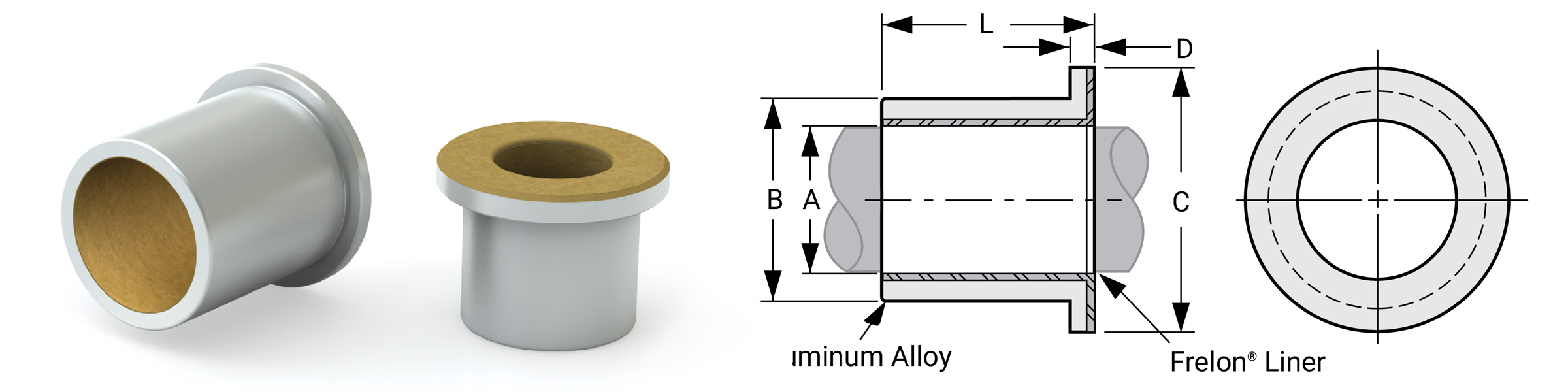
Dimensional Information
| Part No. | Nominal Bearing Size mm |
A Bearing I.D. |
B O.D. S7 |
C Flange O.D. |
D Flange Width |
L Length |
Max Static Load Kg. Frelon® |
Max Static Load N Frelon® |
Bearing Weight |
Recommended Housing Bore | ||||||||||
|---|---|---|---|---|---|---|---|---|---|---|---|---|---|---|---|---|---|---|---|---|
| Slip Fit & Epoxy | Press Fit | |||||||||||||||||||
| I.D. | O.D. | Length | MIN | MAX | MIN | MAX | MIN | MAX | GOLD | J & W | GOLD | J & W | Kg | MIN | MAX | MIN | MAX | |||
| PSFM0610-06 | 6 | 10 | 6 | 6.028 | 6.058 | 10.023 | 10.038 | 14 | 2 | 5.75 | 6 | 76 | 38 | 745 | 373 | 0.00126 | 10.038 | 10.063 | 10.00 | 10.015 |
| PSFM0610-10 | 6 | 10 | 10 | 6.028 | 6.058 | 10.023 | 10.038 | 14 | 2 | 9.75 | 10 | 126 | 63 | 1236 | 618 | 0.00182 | 10.038 | 10.063 | 10.00 | 10.015 |
| PSFM0812-06 | 8 | 12 | 6 | 8.033 | 8.066 | 12.028 | 12.046 | 16 | 2 | 5.75 | 6 | 100 | 50 | 981 | 490 | 0.00153 | 12.046 | 12.071 | 12.00 | 12.018 |
| PSFM0812-08 | 8 | 12 | 8 | 8.033 | 8.066 | 12.028 | 12.046 | 16 | 2 | 7.75 | 8 | 134 | 67 | 1314 | 657 | 0.00189 | 12.046 | 12.071 | 12.00 | 12.018 |
| PSFM0812-12 | 8 | 12 | 12 | 8.033 | 8.066 | 12.028 | 12.046 | 16 | 2 | 11.75 | 12 | 202 | 101 | 1981 | 990 | 0.00259 | 12.046 | 12.071 | 12.00 | 12.018 |
| PSFM1016-08 | 10 | 16 | 8 | 10.033 | 10.066 | 16.028 | 16.046 | 22 | 3 | 7.75 | 8 | 168 | 84 | 1647 | 824 | 0.00421 | 16.046 | 16.071 | 16.00 | 16.018 |
| PSFM1016-10 | 10 | 16 | 10 | 10.033 | 10.066 | 16.028 | 16.046 | 22 | 3 | 9.75 | 10 | 210 | 105 | 2059 | 1030 | 0.00489 | 16.046 | 16.071 | 16.00 | 16.018 |
| PSFM1016-16 | 10 | 16 | 16 | 10.033 | 10.066 | 16.028 | 16.046 | 22 | 3 | 15.75 | 16 | 336 | 168 | 3295 | 1647 | 0.00694 | 16.046 | 16.071 | 16.00 | 16.018 |
| PSFM1218-08 | 12 | 18 | 8 | 12.034 | 12.070 | 18.028 | 18.046 | 24 | 3 | 7.75 | 8 | 202 | 101 | 1981 | 990 | 0.00478 | 18.046 | 18.071 | 18.00 | 18.018 |
| PSFM1218-12 | 12 | 18 | 12 | 12.034 | 12.070 | 18.028 | 18.046 | 24 | 3 | 11.75 | 12 | 302 | 151 | 2961 | 1481 | 0.00636 | 18.046 | 18.071 | 18.00 | 18.018 |
| PSFM1519-16 | 15 | 19 | 16 | 15.034 | 15.070 | 19.028 | 19.046 | 25 | 3 | 15.50 | 16 | 504 | 252 | 4942 | 2471 | 0.00647 | 19.046 | 19.071 | 19.00 | 19.018 |
| PSFM1620-16 | 16 | 20 | 16 | 16.041 | 16.080 | 20.035 | 20.056 | 27 | 3 | 15.55 | 16 | 538 | 269 | 5276 | 2638 | 0.00718 | 20.056 | 20.081 | 20.00 | 20.021 |
Ordering Information
| Type | I.D. | O.D. | Length | |
| PSM | 16 | 20 | - | 16 |
TypePSM = Precision Sleeve Bearing PSFM = Precision Sleeve Bearing with Flange I.D.16 = I.D. in mm O.D.20 = O.D. in mm Length16 = Length in mm |
Note: Lengths not listed above must be specially quoted.
Installation Instructions
- Slip the bearing sleeve into the housing and epoxy into place with Loctite® or similar type bonding agent.
CAUTION: Do NOT let any of the adhesive touch the bearing liner. It will harden and interfere with the running clearance. - Freeze the bearings at 0°F (-17.75°C) for 30-45 minutes. Using gloves, remove the bearings from the freezer and slip them into the housing. As they heat to room temperature, full contact between the bearing and housing will be achieved. The greatest advantage to this technique over traditional pressing is greater accuracy in alignment.
⚠ Only certified Simplicity 60 Plus Shafting provides maximum bearing performance.
Linear Metric Ball Bearings Precision
Plus Self Aligning
Self Aligning Ball Bearings EPS & EPS_OP
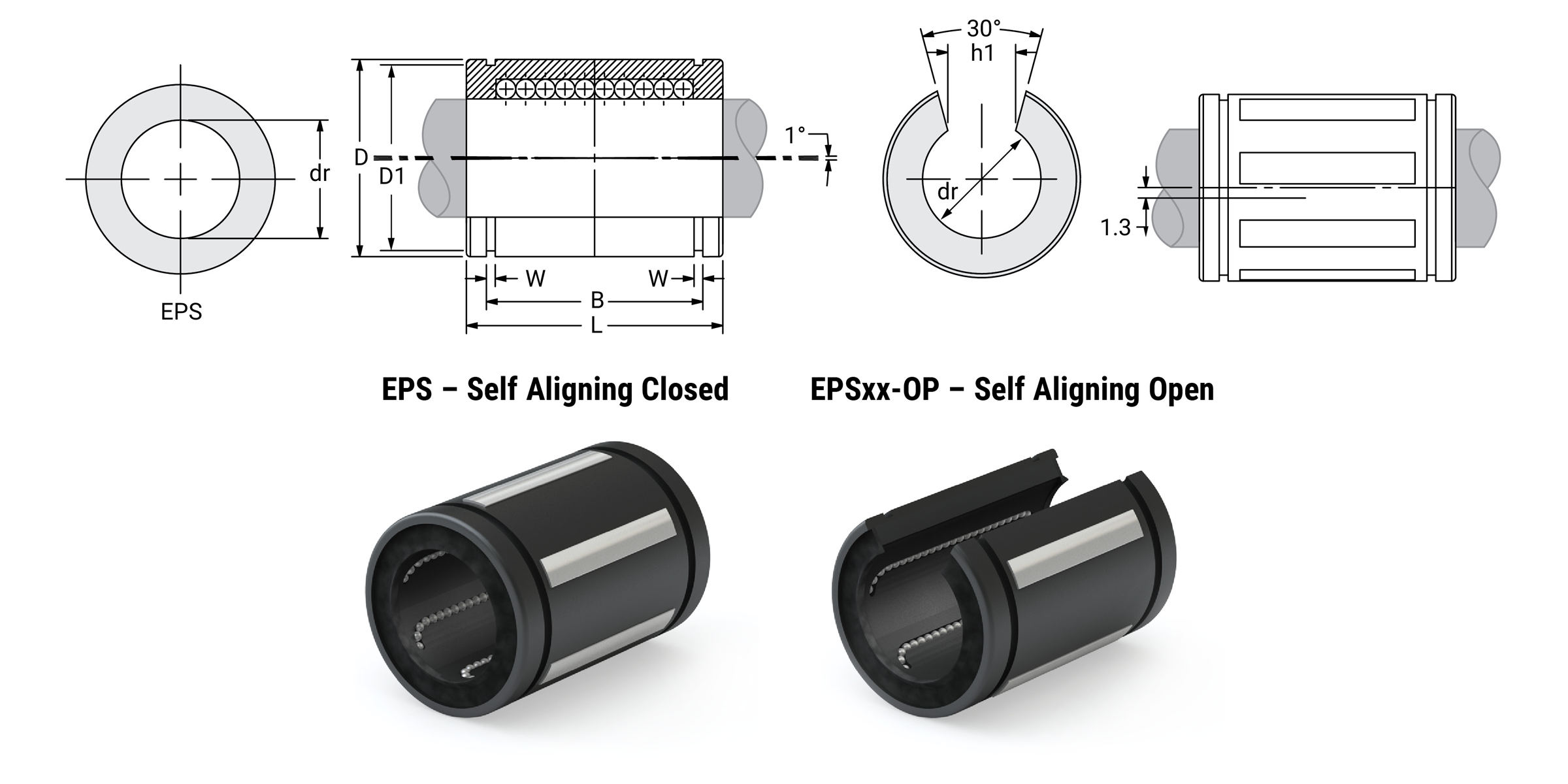
Dimensional Information
| Part No. Self Aligning Closed |
Nominal Diameter | Ball Circuit | Weight G |
Major Dimensions & Tolerances | Load Ratings | |||||||||
|---|---|---|---|---|---|---|---|---|---|---|---|---|---|---|
| Size mm |
dr mm |
Tolerance mm |
D mm |
L mm |
Tolerance mm |
B mm |
Tolerance mm |
W mm |
D1 mm |
Dynamic C N |
Static Co N |
|||
| EPS16 | 16 | 16 | 0/-0.013 | 5 | 26 | 26 | 36 | 0/-0.51 | 24.6 | 0/-0.51 | 1.30 | 24.9 | 1140 | 710 |
| EPS20 | 20 | 20 | 0/-0.013 | 6 | 60 | 32 | 45 | 0/-0.51 | 31.2 | 0/-0.51 | 1.60 | 30.5 | 2280 | 1400 |
| EPS25 | 25 | 25 | 0/-0.013 | 6 | 120 | 40 | 58 | 0/-0.51 | 43.7 | 0/-0.51 | 1.85 | 38.5 | 3800 | 2740 |
| EPS30 | 30 | 30 | 0/-0.013 | 6 | 184 | 47 | 68 | 0/-0.64 | 51.7 | 0/-0.64 | 1.85 | 44.5 | 4710 | 2800 |
| EPS40 | 40 | 40 | 0/-0.013 | 6 | 342 | 62 | 80 | 0/-0.76 | 60.3 | 0/-0.76 | 2.15 | 58.5 | 6500 | 5460 |
| EPS50 | 50 | 50 | 0/-0.013 | 6 | 586 | 75 | 100 | 0/-1.02 | 77.3 | 0/-1.02 | 2.65 | 71.5 | 11460 | 7940 |
| Part No. Self Aligning Open |
Nominal Diameter | Ball Circuit | Weight G |
Major Dimensions & Tolerances | Load Ratings | |||||||||||
|---|---|---|---|---|---|---|---|---|---|---|---|---|---|---|---|---|
| Size mm |
dr mm |
Tolerance mm |
D mm |
L mm |
Tolerance mm |
B mm |
Tolerance mm |
W mm |
D1 mm |
H1 mm |
J mm |
Dynamic C N |
Static Co N |
|||
| EPS16-0P | 16 | 16 | 0/-0.013 | 4 | 20 | 26 | 36 | 0/-0.51 | 24.6 | 0/-0.51 | 1.30 | 24.9 | 0.313 | through | 1330 | 910 |
| EPS20-OP | 20 | 20 | 0/-0.013 | 5 | 50 | 32 | 45 | 0/-0.51 | 31.2 | 0/-0.51 | 1.60 | 30.5 | 0.375 | 0.039 | 2310 | 1445 |
| EPS25-OP | 25 | 25 | 0/-0.013 | 5 | 100 | 40 | 58 | 0/-0.51 | 43.7 | 0/-0.51 | 1.85 | 38.5 | 0.438 | 0.059 | 3910 | 2820 |
| EPS30-OP | 30 | 30 | 0/-0.013 | 5 | 154 | 47 | 68 | 0/-0.64 | 51.7 | 0/-0.64 | 1.85 | 44.5 | 0.563 | 0.047 | 4850 | 2900 |
| EPS40-OP | 40 | 40 | 0/-0.013 | 5 | 286 | 62 | 80 | 0/-0.76 | 60.3 | 0/-0.76 | 2.15 | 58.5 | 0.625 | 0.090 | 6700 | 5625 |
| EPS50-OP | 50 | 50 | 0/-0.013 | 5 | 486 | 75 | 100 | 0/-1.02 | 77.3 | 0/-1.02 | 2.65 | 71.5 | 0.750 | 0.090 | 11700 | 8100 |
Linear Metric Ball Bearings Precision
Ball Bearings EP
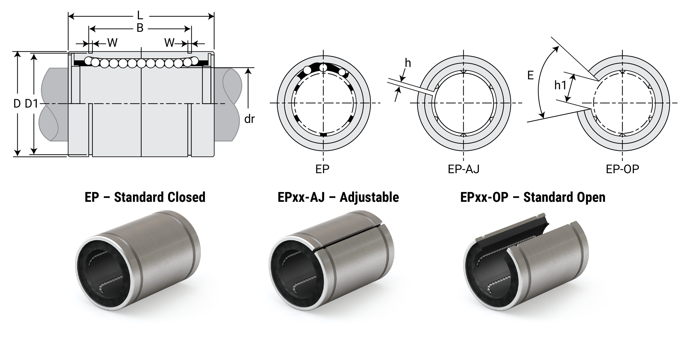
Dimensional Information
| Part No. | Nominal Diameter | Ball Circuit | Weight G |
Major Dimensions & Tolerances | |||||||||
|---|---|---|---|---|---|---|---|---|---|---|---|---|---|
| Standard Closed |
Adjustable | Standard Open |
Size mm |
dr mm |
Tolerance mm |
D mm |
Tolerance mm |
L mm |
Tolerance mm |
B mm |
Tolerance mm |
||
| EP5G | - | - | 5 | 5 | +0.008/0 | 4 | 11 | 12 | 0/-0.008 | 22 | 0/-0.2 | 14.5 | 0/-0.2 |
| EP8G | - | - | 8 | 8 | +0.008/0 | 4 | 20 | 16 | 0/-0.008 | 25 | 0/-0.2 | 16.5 | 0/-0.2 |
| EP10G | - | - | 10 | 10 | +0.008/0 | 4 | 36 | 19 | 0/-0.009 | 29 | 0/-0.2 | 22 | 0/-0.2 |
| EP12G | EP12G-AJ | EP12G-OP | 12 | 12 | +0.008/0 | 5 | 41 | 22 | 0/-0.009 | 32 | 0/-0.2 | 22.9 | 0/-0.2 |
| EP16G | EP16G-AJ | EP16G-OP | 16 | 16 | +0.009/-0.001 | 5 | 65 | 26 | 0/-0.009 | 36 | 0/-0.2 | 24.9 | 0/-0.2 |
| EP20G | EP20G-AJ | EP20G-OP | 20 | 20 | +0.009/-0.001 | 5 | 91 | 32 | 0/-0.011 | 45 | 0/-0.2 | 31.5 | 0/-0.2 |
| EP25G | EP25G-AJ | EP25G-OP | 25 | 25 | +0.011/-0.001 | 6 | 215 | 40 | 0/-0.011 | 58 | 0/-0.3 | 44.1 | 0/-0.3 |
| EP30G | EP30G-AJ | EP30G-OP | 30 | 30 | +0.011/-0.001 | 6 | 325 | 47 | 0/-0.011 | 68 | 0/-0.3 | 52.1 | 0/-0.3 |
| EP40G | EP40G-AJ | EP40G-OP | 40 | 40 | +0.013/-0.002 | 6 | 705 | 62 | 0/-0.013 | 80 | 0/-0.3 | 60.6 | 0/-0.3 |
| EP50G | EP50G-AJ | EP50G-OP | 50 | 50 | +0.013/-0.002 | 6 | 1130 | 75 | 0/-0.013 | 100 | 0/-0.3 | 77.6 | 0/-0.3 |
| Part No. | Nominal Diameter | Major Dimensions & Tolerances | Load Ratings | |||||||||||
|---|---|---|---|---|---|---|---|---|---|---|---|---|---|---|
| Standard Closed |
Adjustable | Standard Open |
Size mm |
dr mm |
Tolerance mm |
W mm |
D1 mm |
H mm |
H1 mm |
E Slot Angle |
MAX Eccentricity μm |
MAX Radial Clearance μm |
Dynamic C N |
Static Co N |
| EP5G | - | - | 5 | 5 | +0.008/0 | 1.1 | 11.5 | - | - | - | 12 | -5 | 200 | 260 |
| EP8G | - | - | 8 | 8 | +0.008/0 | 1.1 | 15.2 | - | - | - | 12 | -5 | 260 | 400 |
| EP10G | - | - | 10 | 10 | +0.008/0 | 1.3 | 18 | - | - | - | 12 | -5 | 372 | 549 |
| EP12G | EP12G-AJ | EP12G-OP | 12 | 12 | +0.008/0 | 1.3 | 21 | 1.5 | 7.5 | 78° | 12 | -7 | 410 | 590 |
| EP16G | EP16G-AJ | EP16G-OP | 16 | 16 | +0.009/-0.001 | 1.3 | 24.9 | 1.5 | 10 | 78° | 12 | -7 | 770 | 1170 |
| EP20G | EP20G-AJ | EP20G-OP | 20 | 20 | +0.009/-0.001 | 1.6 | 30.3 | 2 | 10 | 60° | 15 | -9 | 860 | 1370 |
| EP25G | EP25G-AJ | EP25G-OP | 25 | 25 | +0.011/-0.001 | 1.85 | 37.5 | 2 | 12.5 | 60° | 15 | -9 | 980 | 1560 |
| EP30G | EP30G-AJ | EP30G-OP | 30 | 30 | +0.011/-0.001 | 1.85 | 44.5 | 2 | 12.5 | 50° | 15 | -9 | 1560 | 2740 |
| EP40G | EP40G-AJ | EP40G-OP | 40 | 40 | +0.013/-0.002 | 2.15 | 59 | 3 | 16.8 | 50° | 17 | -13 | 2150 | 4010 |
| EP50G | EP50G-AJ | EP50G-OP | 50 | 50 | +0.013/-0.002 | 2.65 | 72 | 3 | 21 | 50° | 17 | -13 | 3820 | 7930 |
Linear Metric Ball Bearings
Double Wide
Double Wide Ball Bearings EP-W
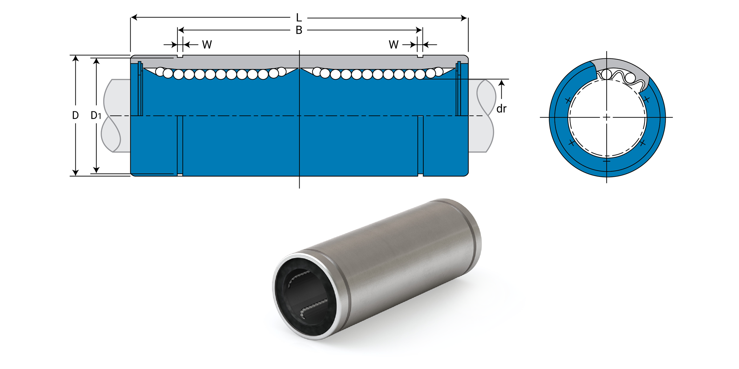
Dimensional Information
| Part No. Standard Closed |
Nominal Diameter | Ball Circuit | Weight G |
Major Dimensions & Tolerances | |||||||
|---|---|---|---|---|---|---|---|---|---|---|---|
| Size mm |
dr mm |
Tolerance mm |
D mm |
Tolerance mm |
L mm |
Tolerance mm |
B mm |
Tolerance mm |
|||
| EP8GW | 8 | 8 | +0.009/-0.001 | 4 | 40 | 16 | 0/-0.009 | 45 | 0/-0.3 | 33 | 0/-0.3 |
| EP12GW | 12 | 12 | +0.009/-0.001 | 4 | 80 | 22 | 0/-0.011 | 61 | 0/-0.3 | 45.8 | 0/-0.3 |
| EP16GW | 16 | 16 | +0.011/-0.001 | 5 | 115 | 26 | 0/-0.011 | 68 | 0/-0.3 | 49.8 | 0/-0.3 |
| EP20GW | 20 | 20 | +0.011/-0.001 | 5 | 180 | 32 | 0/-0.013 | 80 | 0/-0.3 | 61 | 0/-0.3 |
| EP25GW | 25 | 25 | +0.013/-0.002 | 6 | 430 | 40 | 0/-0.013 | 112 | 0/-0.4 | 82 | 0/-0.4 |
| EP30GW | 30 | 30 | +0.013/-0.002 | 6 | 615 | 47 | 0/-0.013 | 123 | 0/-0.4 | 104.2 | 0/-0.4 |
| EP40GW | 40 | 40 | +0.016/-0.004 | 6 | 1400 | 62 | 0/-0.015 | 151 | 0/-0.4 | 121.2 | 0/-0.4 |
| EP50GW | 50 | 50 | +0.016/-0.004 | 6 | 2320 | 75 | 0/-0.020 | 192 | 0/-0.4 | 155.2 | 0/-0.4 |
| Part No. Standard Closed |
Nominal Diameter | Major Dimensions & Tolerances | Load Ratings | |||||
|---|---|---|---|---|---|---|---|---|
| Size mm |
dr mm |
Tolerance mm |
W mm |
D1 mm |
MAX Eccentricity μm |
Dynamic C N |
Static Co N |
|
| EP8GW | 8 | 8 | +0.009/-0.001 | 1.1 | 15.2 | 15 | 421 | 804 |
| EP12GW | 12 | 12 | +0.009/-0.001 | 1.3 | 21 | 15 | 813 | 1570 |
| EP16GW | 16 | 16 | +0.011/-0.001 | 1.3 | 24.9 | 15 | 921 | 1780 |
| EP20GW | 20 | 20 | +0.011/-0.001 | 1.6 | 30.3 | 17 | 1370 | 2740 |
| EP25GW | 25 | 25 | +0.013/-0.002 | 1.85 | 38 | 17 | 1570 | 3140 |
| EP30GW | 30 | 30 | +0.013/-0.002 | 1.85 | 44.5 | 17 | 2500 | 5490 |
| EP40GW | 40 | 40 | +0.016/-0.004 | 2.15 | 59 | 20 | 3430 | 8040 |
| EP50GW | 50 | 50 | +0.016/-0.004 | 2.65 | 72 | 20 | 6080 | 15900 |
⚠ Only certified Simplicity 60 Plus Shafting provides maximum bearing performance.
Linear Metric Ball Bearings
Pillow Blocks
Ball Bearings – Closed Pillow Blocks EPPM
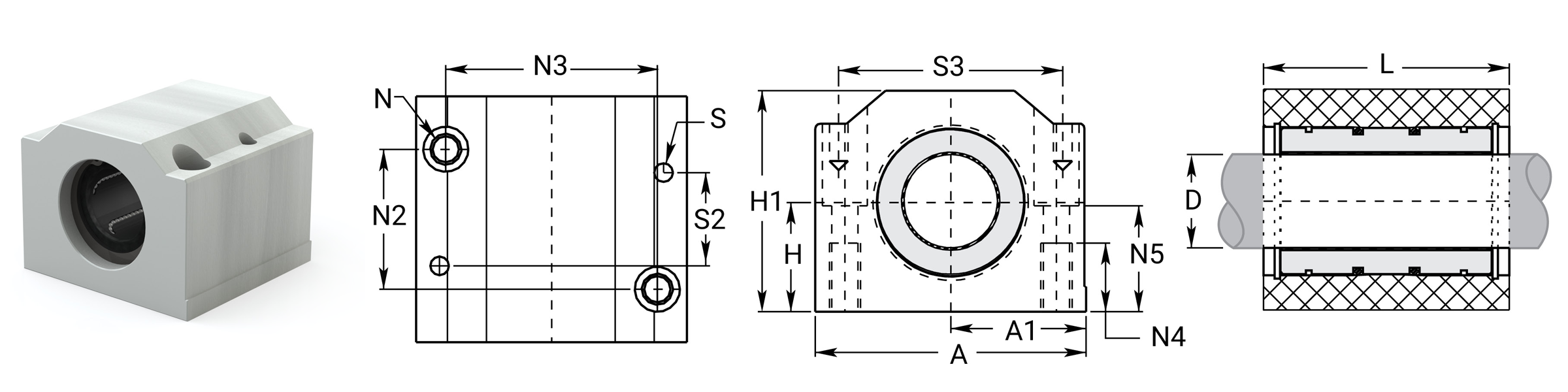
| Part No. Precision |
D Nom. Brg. I.D. mm |
H Centerline +/- 0.015 mm |
H1 Height mm |
A Width mm |
A1 Centerline +/- 0.013 mm |
L Length mm |
N Bolt |
N2 mm |
N3 mm |
N4 mm |
N5 mm |
S mm |
S2 mm |
S3 mm |
Assem. WT kg |
Load Ratings | |
|---|---|---|---|---|---|---|---|---|---|---|---|---|---|---|---|---|---|
| Dynamic C N |
Static Co N |
||||||||||||||||
| EPPM08G | 8 | 15 | 28 | 35 | 17.5 | 32 | M4 x 0.7 | 20 | 25 | 9 | 14.5 | N/A | N/A | N/A | 0.069 | 260 | 400 |
| EPPM10G | 10 | 16 | 31.5 | 40 | 20 | 36 | M5 x 0.8 | 20 | 29 | 11 | 15 | 4 | 29 | 31 | 0.095 | 372 | 549 |
| EPPM12G | 12 | 18 | 35 | 43 | 21.5 | 39 | M5 x 0.8 | 23 | 32 | 11 | 16.5 | 4 | 32 | 34 | 0.118 | 410 | 590 |
| EPPM16G | 16 | 22 | 42 | 53 | 26.5 | 43 | M6 x 1.0 | 26 | 40 | 13 | 21 | 4 | 35 | 42 | 0.200 | 770 | 1170 |
| EPPM20G | 20 | 25 | 50 | 60 | 30 | 54 | M8 x 1.25 | 32 | 45 | 18 | 24 | 5 | 45 | 50 | 0.329 | 860 | 1370 |
| EPPM25G | 25 | 30 | 60 | 78 | 39 | 67 | M10 x 1.5 | 40 | 60 | 22 | 29 | 6 | 20 | 64 | 0.655 | 980 | 1560 |
| EPPM30G | 30 | 35 | 71 | 87 | 43.5 | 79 | M10 x 1.5 | 45 | 68 | 22 | 34 | 6 | 30 | 72 | 1.020 | 1560 | 2740 |
| EPPM40G | 40 | 45 | 91 | 108 | 54 | 91 | M12 x 1.75 | 58 | 86 | 26 | 44 | 8 | 35 | 90 | 1.846 | 2150 | 4010 |
| EPPM50G | 50 | 50 | 105 | 132 | 66 | 113 | M16 x 2.0 | 50 | 105 | 34 | 49 | 10 | 42 | 108 | 3.169 | 3820 | 7930 |
Note:
(1) Standard pillow block assembly includes self-aligning housing.
(2) All standard metric pillow blocks use standard EP series bearings.
(3) Straight bore pillow block assembly includes standard EP series bearing in straight bore housing.
Ball Bearings – Open Pillow Blocks EPPMN
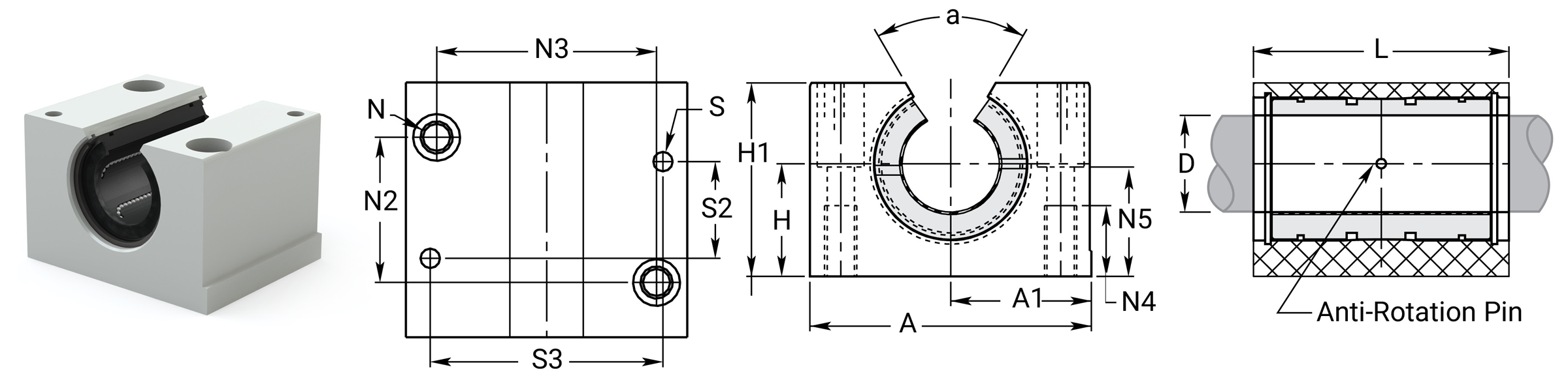
| Part No. Precision |
D Nom. Brg. I.D. mm |
H Centerline +/- 0.015 mm |
H1 Height mm |
A Width mm |
A1 Centerline +/- 0.013 mm |
L Length mm |
N Bolt |
N2 mm |
N3 mm |
N4 mm |
N5 mm |
S mm |
S2 mm |
S3 mm |
A mm |
Assem. WT kg |
Load Ratings | |
|---|---|---|---|---|---|---|---|---|---|---|---|---|---|---|---|---|---|---|
| Dynamic C N |
Static Co N |
|||||||||||||||||
| EPPMN12G | 12 | 18 | 28 | 43 | 21.5 | 39 | M5 x 0.8 | 23 | 32 | 11 | 16.5 | 4 | 32 | 34 | 66 | 0.096 | 410 | 590 |
| EPPMN16G | 16 | 22 | 35 | 53 | 26.5 | 43 | M6 x 1 | 26 | 40 | 13 | 21 | 4 | 35 | 42 | 68 | 0.162 | 770 | 1170 |
| EPPMN20G | 20 | 25 | 42 | 60 | 30 | 54 | M8 x 1.25 | 32 | 45 | 18 | 24 | 5 | 45 | 50 | 60 | 0.267 | 860 | 1370 |
| EPPMN25G | 25 | 30 | 51 | 78 | 39 | 67 | M10 x 1.5 | 40 | 60 | 22 | 29 | 6 | 20 | 64 | 60 | 0.536 | 980 | 1560 |
| EPPMN30G | 30 | 35 | 60 | 87 | 43.5 | 79 | M10 x 1.5 | 45 | 68 | 22 | 34 | 6 | 30 | 72 | 60 | 0.831 | 1560 | 2740 |
| EPPMN40G | 40 | 45 | 77 | 108 | 54 | 91 | M12 x 1.75 | 58 | 86 | 26 | 44 | 8 | 35 | 90 | 60 | 1.499 | 2150 | 4010 |
| EPPMN50G | 50 | 50 | 88 | 132 | 66 | 113 | M16 x 2 | 50 | 105 | 34 | 49 | 10 | 42 | 108 | 60 | 2.539 | 3820 | 7930 |
Note:
(1) Standard pillow block assembly includes self-aligning housing.
(2) All standard metric pillow blocks use standard EP series bearings.
Linear Metric Ball Bearings
Square Flange Mount
Ball Bearings – Square Flange Mount EPK
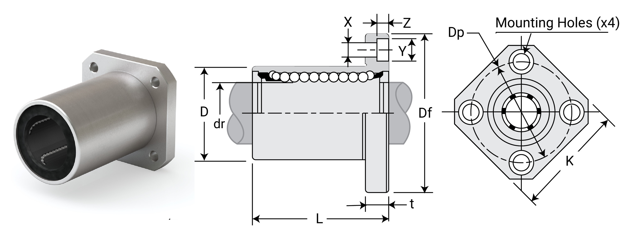
Dimensional Information
| Part No. Standard Polymer Cage |
Nominal Diameter | Ball Circuit | Weight G |
Major Dimensions & Tolerances | |||||
|---|---|---|---|---|---|---|---|---|---|
| Size mm |
dr mm |
Tolerance mm |
D mm |
Tolerance mm |
L mm |
Tolerance | |||
| EPK8G | 8 | 8 | +0.008/0 | 4 | 41 | 16 | 0/-0.013 | 25 | ±0.3 |
| EPK12G | 12 | 12 | +0.008/0 | 4 | 80 | 22 | 0/-0.016 | 32 | ±0.3 |
| EPK16G | 16 | 16 | +0.009/-0.001 | 5 | 103 | 26 | 0/-0.016 | 36 | ±0.3 |
| EPK20G | 20 | 20 | +0.009/-0.001 | 5 | 182 | 32 | 0/-0.019 | 45 | ±0.3 |
| EPK25G | 25 | 25 | +0.011/-0.001 | 6 | 335 | 40 | 0/-0.019 | 58 | ±0.3 |
| EPK30G | 30 | 30 | +0.011/-0.001 | 6 | 560 | 47 | 0/-0.019 | 68 | ±0.3 |
| EPK40G | 40 | 40 | +0.013/-0.002 | 6 | 1175 | 62 | 0/-0.022 | 80 | ±0.3 |
| EPK50G | 50 | 50 | +0.013/-0.002 | 6 | 1745 | 75 | 0/-0.022 | 100 | ±0.3 |
| Part No. Standard Polymer Cage |
Nominal Diameter | Major Dimensions & Tolerances – Flange | Load Ratings | |||||||||||
|---|---|---|---|---|---|---|---|---|---|---|---|---|---|---|
| Size mm |
dr mm |
Tolerance mm |
Df mm |
K mm |
T mm |
DP mm |
X mm |
Y mm |
Z mm |
Eccentricity µm |
Squareness µm |
Dynamic C N |
Static Co N |
|
| EPK8G | 8 | 8 | +0.008/0 | 32 | 25 | 5 | 24 | 3.5 | 6.5 | 3.1 | 12 | 12 | 265 | 402 |
| EPK12G | 12 | 12 | +0.008/0 | 42 | 32 | 6 | 32 | 4.5 | 8 | 4.1 | 12 | 12 | 510 | 784 |
| EPK16G | 16 | 16 | +0.009/-0.001 | 46 | 35 | 6 | 36 | 4.5 | 8 | 4.1 | 12 | 12 | 578 | 892 |
| EPK20G | 20 | 20 | +0.009/-0.001 | 54 | 42 | 8 | 43 | 5.5 | 9.3 | 5.1 | 15 | 15 | 862 | 1370 |
| EPK25G | 25 | 25 | +0.011/-0.001 | 62 | 50 | 8 | 51 | 5.5 | 9.3 | 5.1 | 15 | 15 | 980 | 1570 |
| EPK30G | 30 | 30 | +0.011/-0.001 | 76 | 60 | 10 | 62 | 6.6 | 11 | 6.1 | 15 | 15 | 1570 | 2740 |
| EPK40G | 40 | 40 | +0.013/-0.002 | 98 | 75 | 13 | 80 | 9 | 14 | 8.1 | 17 | 17 | 2160 | 4020 |
| EPK50G | 50 | 50 | +0.013/-0.002 | 112 | 88 | 13 | 94 | 9 | 14 | 8.1 | 17 | 17 | 3820 | 7940 |
⚠ Only certified Simplicity 60 Plus Shafting provides maximum bearing performance.
Linear Metric Ball Bearings
Round Flange Mount
Ball Bearings – Round Flange Mount EPF
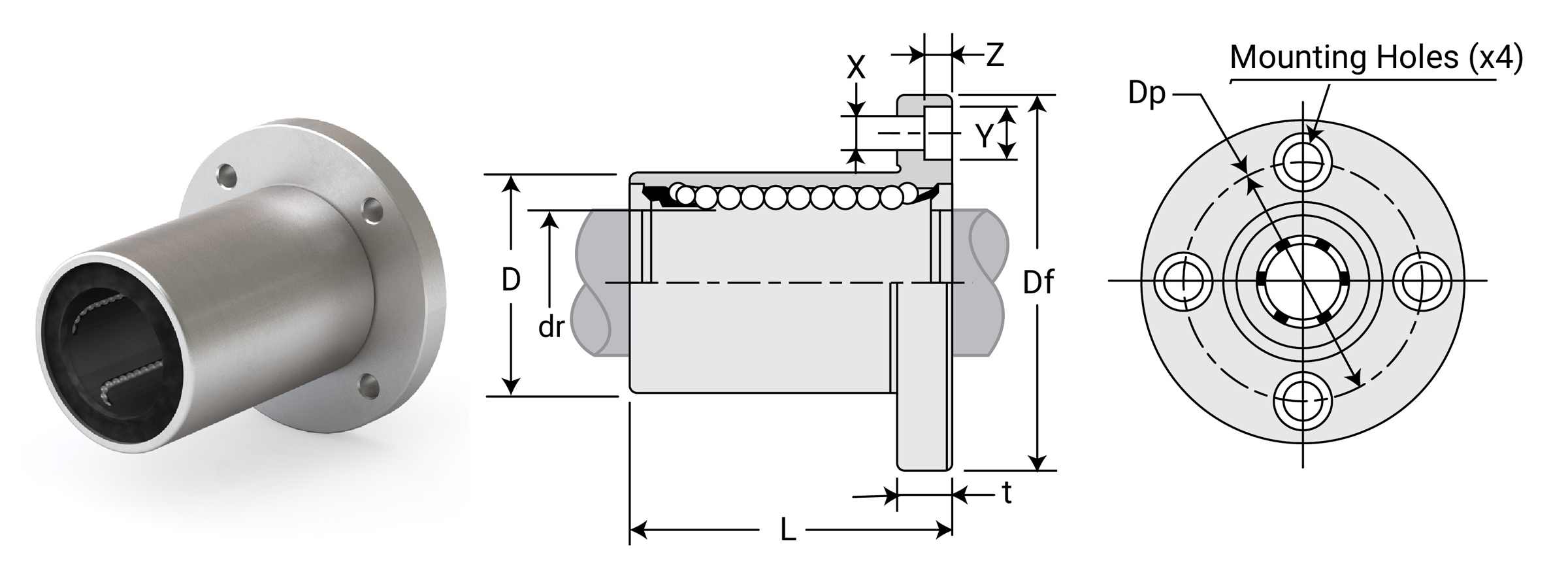
Dimensional Information
| Part No. Standard Polymer Cage |
Nominal Diameter | Ball Circuit | Weight G |
Major Dimensions & Tolerances | |||||
|---|---|---|---|---|---|---|---|---|---|
| Size mm |
dr mm |
Tolerance mm |
D mm |
Tolerance mm |
L mm |
Tolerance mm |
|||
| EPF8G | 8 | 8 | +0.008/0 | 4 | 41 | 16 | 0/-0.013 | 25 | ±0.3 |
| EPF12G | 12 | 12 | +0.008/0 | 4 | 80 | 22 | 0/-0.016 | 32 | ±0.3 |
| EPF16G | 16 | 16 | +0.009/-0.001 | 5 | 103 | 26 | 0/-0.016 | 36 | ±0.3 |
| EPF20G | 20 | 20 | +0.009/-0.001 | 5 | 182 | 32 | 0/-0.019 | 45 | ±0.3 |
| EPF25G | 25 | 25 | +0.011/-0.001 | 6 | 335 | 40 | 0/-0.019 | 58 | ±0.3 |
| EPF30G | 30 | 30 | +0.011/-0.001 | 6 | 560 | 47 | 0/-0.019 | 68 | ±0.3 |
| EPF40G | 40 | 40 | +0.013/-0.002 | 6 | 1175 | 62 | 0/-0.022 | 80 | ±0.3 |
| EPF50G | 50 | 50 | +0.013/-0.002 | 6 | 1745 | 75 | 0/-0.022 | 100 | ±0.3 |
| Part No. Standard Polymer Cage |
Nominal Diameter | Major Dimensions & Tolerances – Flange | Load Ratings | ||||||||||
|---|---|---|---|---|---|---|---|---|---|---|---|---|---|
| Size mm |
dr mm |
Tolerance mm |
Df mm |
T mm |
Dp mm |
X mm |
Y mm |
Z mm |
Eccentricity µm |
Squareness µm |
Dynamic C N |
Static Co N |
|
| EPF8G | 8 | 8 | +0.008/0 | 32 | 5 | 24 | 3.5 | 6.5 | 3.1 | 12 | 12 | 265 | 402 |
| EPF12G | 12 | 12 | +0.008/0 | 42 | 6 | 32 | 4.5 | 8 | 4.1 | 12 | 12 | 510 | 784 |
| EPF16G | 16 | 16 | +0.009/-0.001 | 46 | 6 | 36 | 4.5 | 8 | 4.1 | 12 | 12 | 578 | 892 |
| EPF20G | 20 | 20 | +0.009/-0.001 | 54 | 8 | 43 | 5.5 | 9.3 | 5.1 | 15 | 15 | 862 | 1370 |
| EPF25G | 25 | 25 | +0.011/-0.001 | 62 | 8 | 51 | 5.5 | 9.3 | 5.1 | 15 | 15 | 980 | 1570 |
| EPF30G | 30 | 30 | +0.011/-0.001 | 76 | 10 | 62 | 6.6 | 11 | 6.1 | 15 | 15 | 1570 | 2740 |
| EPF40G | 40 | 40 | +0.013/-0.002 | 98 | 13 | 80 | 9 | 14 | 8.1 | 17 | 17 | 2160 | 4020 |
| EPF50G | 50 | 50 | +0.013/-0.002 | 112 | 13 | 94 | 9 | 14 | 8.1 | 17 | 17 | 3820 | 7940 |
⚠ Only certified Simplicity 60 Plus Shafting provides maximum bearing performance.
Linear Metric Ball Bearings
Double Wide
Double Wide Ball Bearings – Square Flange Mount EPK-W
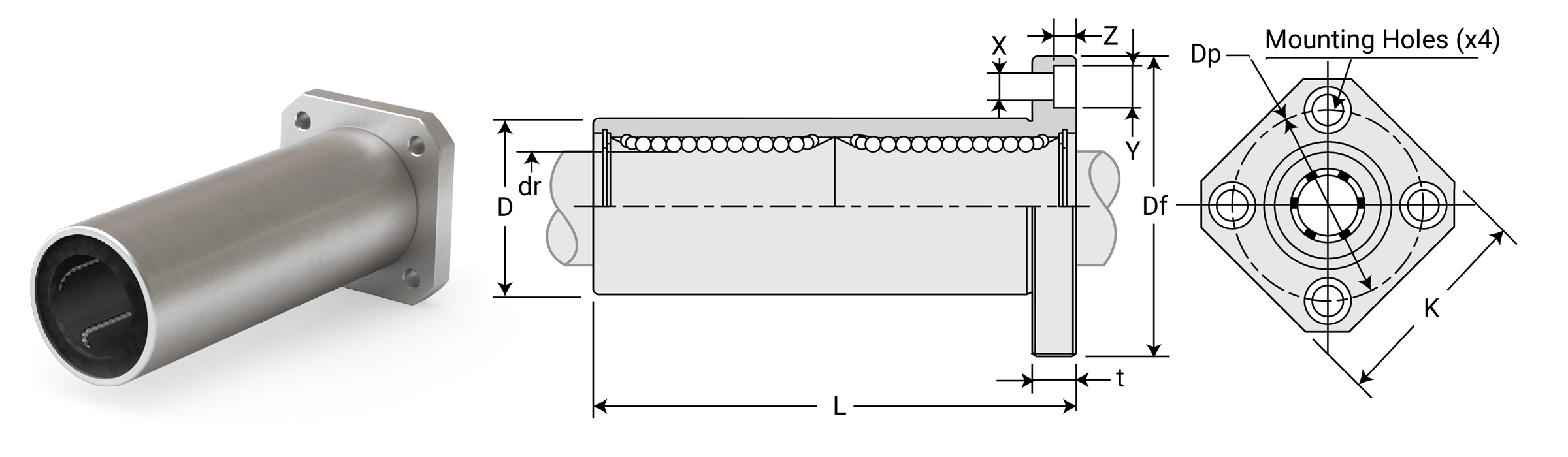
Dimensional Information
| Part No. Standard Polymer Cage |
Nominal Diameter | Ball Circuit | Weight G |
Major Dimensions & Tolerances | |||||
|---|---|---|---|---|---|---|---|---|---|
| Size mm |
dr mm |
Tolerance mm |
D mm |
Tolerance mm |
L mm |
Tolerance mm |
|||
| EPK8GW | 8 | 8 | +0.009/-0.001 | 4 | 51 | 16 | 0/-0.013 | 45 | ±0.3 |
| EPK12GW | 12 | 12 | +0.009/-0.001 | 4 | 90 | 22 | 0/-0.016 | 61 | ±0.3 |
| EPK16GW | 16 | 16 | +0.011/-0.001 | 5 | 135 | 26 | 0/-0.016 | 70 | ±0.3 |
| EPK20GW | 20 | 20 | +0.011/-0.001 | 5 | 225 | 32 | 0/-0.019 | 80 | ±0.3 |
| EPK25GW | 25 | 25 | +0.013/-0.002 | 6 | 500 | 40 | 0/-0.019 | 112 | ±0.3 |
| EPK30GW | 30 | 30 | +0.013/-0.002 | 6 | 720 | 47 | 0/-0.019 | 123 | ±0.3 |
| EPK40GW | 40 | 40 | +0.016/-0.004 | 6 | 1600 | 62 | 0/-0.022 | 154 | ±0.3 |
| EPK50GW | 50 | 50 | +0.016/-0.004 | 6 | 2620 | 75 | 0/-0.022 | 192 | ±0.3 |
| Part No. Standard Polymer Cage |
Nominal Diameter | Major Dimensions & Tolerances – Flange | Load Ratings | |||||||||||
|---|---|---|---|---|---|---|---|---|---|---|---|---|---|---|
| Size mm |
dr mm |
Tolerance mm |
Df mm |
K mm |
T mm |
DP mm |
X mm |
Y mm |
Z mm |
Eccentricity µm |
Squareness µm |
Dynamic C N |
Static Co N |
|
| EPK8GW | 8 | 8 | +0.009/-0.001 | 32 | 25 | 5 | 24 | 3.5 | 6.5 | 3.1 | 15 | 15 | 421 | 804 |
| EPK12GW | 12 | 12 | +0.009/-0.001 | 42 | 32 | 6 | 32 | 4.5 | 8 | 4.1 | 15 | 15 | 813 | 1570 |
| EPK16GW | 16 | 16 | +0.011/-0.001 | 46 | 35 | 6 | 36 | 4.5 | 8 | 4.1 | 15 | 15 | 921 | 1780 |
| EPK20GW | 20 | 20 | +0.011/-0.001 | 54 | 42 | 8 | 43 | 5.5 | 9.3 | 5.1 | 17 | 17 | 1370 | 2740 |
| EPK25GW | 25 | 25 | +0.013/-0.002 | 62 | 50 | 8 | 51 | 5.5 | 9.3 | 5.1 | 17 | 17 | 1570 | 3140 |
| EPK30GW | 30 | 30 | +0.013/-0.002 | 76 | 60 | 10 | 62 | 6.6 | 11 | 6.1 | 17 | 17 | 2500 | 5490 |
| EPK40GW | 40 | 40 | +0.016/-0.004 | 98 | 75 | 13 | 80 | 9 | 14 | 8.1 | 20 | 20 | 3430 | 8040 |
| EPK50GW | 50 | 50 | +0.016/-0.004 | 112 | 88 | 13 | 94 | 9 | 14 | 8.1 | 20 | 20 | 6080 | 15900 |
Double Wide Ball Bearings – Round Flange Mount EPF-W
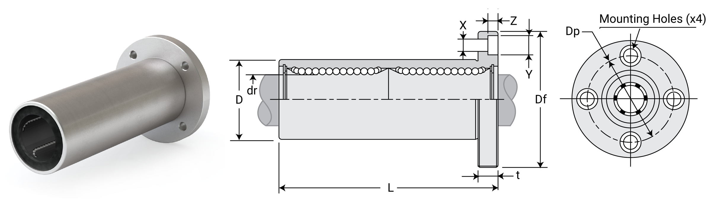
Dimensional Information
| Part No. Standard Polymer Cage |
Nominal Diameter | Ball Circuit | Weight G |
Major Dimensions & Tolerances | |||||
|---|---|---|---|---|---|---|---|---|---|
| Size mm |
dr mm |
Tolerance mm |
D mm |
Tolerance mm |
L mm |
Tolerance mm |
|||
| EPF8GW | 8 | 8 | +0.009/-0.001 | 4 | 59 | 16 | 0/-0.013 | 46 | ±0.3 |
| EPF12GW | 12 | 12 | +0.009/-0.001 | 4 | 110 | 22 | 0/-0.016 | 61 | ±0.3 |
| EPF16GW | 16 | 16 | +0.011/-0.001 | 5 | 160 | 26 | 0/-0.016 | 68 | ±0.3 |
| EPF20GW | 20 | 20 | +0.011/-0.001 | 5 | 260 | 32 | 0/-0.019 | 80 | ±0.3 |
| EPF25GW | 25 | 25 | +0.013/-0.002 | 6 | 540 | 40 | 0/-0.019 | 112 | ±0.3 |
| EPF30GW | 30 | 30 | +0.013/-0.002 | 6 | 815 | 47 | 0/-0.019 | 123 | ±0.3 |
| EPF40GW | 40 | 40 | +0.016/-0.004 | 6 | 1805 | 62 | 0/-0.022 | 154 | ±0.3 |
| EPF50GW | 50 | 50 | +0.016/-0.004 | 6 | 2820 | 75 | 0/-0.022 | 192 | ±0.3 |
| Part No. Standard Polymer Cage |
Nominal Diameter | Major Dimensions & Tolerances – Flange | Load Ratings | ||||||||||
|---|---|---|---|---|---|---|---|---|---|---|---|---|---|
| Size mm |
dr mm |
Tolerance mm |
Df mm |
T mm |
DP mm |
X mm |
Y mm |
Z mm |
Eccentricity µm |
Squareness µm |
Dynamic C N |
Static Co N |
|
| EPF8GW | 8 | 8 | +0.009/-0.001 | 32 | 5 | 24 | 3.5 | 6.5 | 3.1 | 15 | 15 | 421 | 804 |
| EPF12GW | 12 | 12 | +0.009/-0.001 | 42 | 6 | 32 | 4.5 | 8 | 4.1 | 15 | 15 | 813 | 1570 |
| EPF16GW | 16 | 16 | +0.011/-0.001 | 46 | 6 | 36 | 4.5 | 8 | 4.1 | 15 | 15 | 921 | 1780 |
| EPF20GW | 20 | 20 | +0.011/-0.001 | 54 | 8 | 43 | 5.5 | 9.3 | 5.1 | 17 | 17 | 1370 | 2740 |
| EPF25GW | 25 | 25 | +0.013/-0.002 | 62 | 8 | 51 | 5.5 | 9.3 | 5.1 | 17 | 17 | 1570 | 3140 |
| EPF30GW | 30 | 30 | +0.013/-0.002 | 76 | 10 | 62 | 6.6 | 11 | 6.1 | 17 | 17 | 2500 | 5490 |
| EPF40GW | 40 | 40 | +0.016/-0.004 | 98 | 13 | 80 | 9 | 14 | 8.1 | 20 | 20 | 3430 | 8040 |
| EPF50GW | 50 | 50 | +0.016/-0.004 | 112 | 13 | 94 | 9 | 14 | 8.1 | 20 | 20 | 6080 | 15900 |
⚠ Only certified Simplicity 60 Plus Shafting provides maximum bearing performance.
Linear Metric Ball Bearings
Flange Center Mount
Ball Bearings – Square Flange Center Mount EPKC
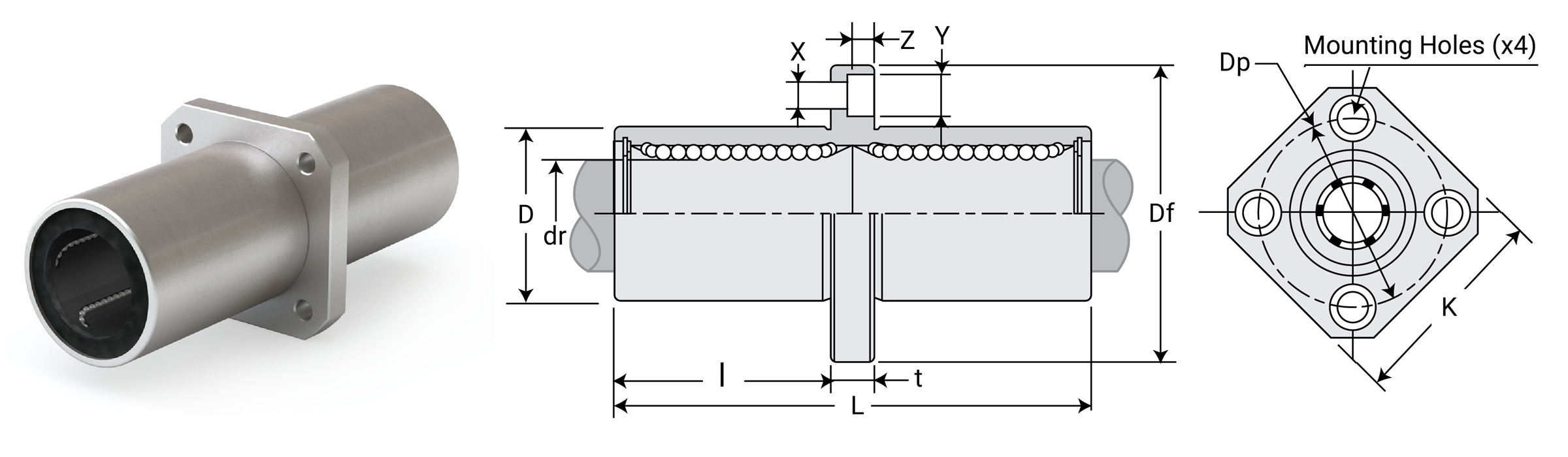
Dimensional Information
| Part No. Standard Polymer Cage |
Nominal Diameter | Ball Circuit | Weight G |
Major Dimensions & Tolerances | |||||
|---|---|---|---|---|---|---|---|---|---|
| Size mm |
dr mm |
Tolerance μm |
D mm |
Tolerance μm |
L mm |
Tolerance μm |
|||
| EPKC8G | 8 | 8 | +9/-1 | 4 | 51 | 16 | 0/-13 | 45 | ±300 |
| EPKC12G | 12 | 12 | +9/-1 | 4 | 90 | 22 | 0/-16 | 57 | ±300 |
| EPKC16G | 16 | 16 | +11/-1 | 5 | 135 | 26 | 0/-16 | 70 | ±300 |
| EPKC20G | 20 | 20 | +11/-1 | 5 | 225 | 32 | 0/-19 | 80 | ±300 |
| EPKC25G | 25 | 25 | +13/-2 | 6 | 500 | 40 | 0/-19 | 112 | ±300 |
| EPKC30G | 30 | 30 | +13/-2 | 6 | 720 | 47 | 0/-19 | 123 | ±300 |
| EPKC40G | 40 | 40 | +16/-4 | 6 | 1600 | 62 | 0/-22 | 154 | ±300 |
| EPKC50G | 50 | 50 | +16/-4 | 6 | 2620 | 75 | 0/-22 | 192 | ±300 |
| Part No. Standard Polymer Cage |
Nominal Diameter | Major Dimensions & Tolerances – Flange | Load Ratings | ||||||||||||
|---|---|---|---|---|---|---|---|---|---|---|---|---|---|---|---|
| Size mm |
dr mm |
Tolerance μm |
I mm |
Df mm |
K mm |
T mm |
DP mm |
X mm |
Y mm |
Z mm |
Eccentricity µm |
Squareness µm |
Dynamic C N |
Static Co N |
|
| EPKC8G | 8 | 8 | +9/-1 | 20.5 | 32 | 25 | 5 | 24 | 3.5 | 6.5 | 3.1 | 15 | 15 | 421 | 804 |
| EPKC12G | 12 | 12 | +9/-1 | 27.5 | 42 | 32 | 6 | 32 | 4.5 | 8 | 4.1 | 15 | 15 | 813 | 1570 |
| EPKC16G | 16 | 16 | +11/-1 | 31 | 46 | 35 | 6 | 36 | 4.5 | 8 | 4.1 | 15 | 15 | 921 | 1780 |
| EPKC20G | 20 | 20 | +11/-1 | 36 | 54 | 42 | 8 | 43 | 5.5 | 9.3 | 5.1 | 17 | 17 | 1370 | 2740 |
| EPKC25G | 25 | 25 | +13/-2 | 52 | 62 | 50 | 8 | 51 | 5.5 | 9.3 | 5.1 | 17 | 17 | 1570 | 3140 |
| EPKC30G | 30 | 30 | +13/-2 | 56.5 | 76 | 60 | 10 | 62 | 6.6 | 11 | 6.1 | 17 | 17 | 2500 | 5490 |
| EPKC40G | 40 | 40 | +16/-4 | 69 | 98 | 75 | 13 | 80 | 9 | 14 | 8.1 | 20 | 20 | 3430 | 8040 |
| EPKC50G | 50 | 50 | +16/-4 | 89.5 | 112 | 88 | 13 | 94 | 9 | 14 | 8.1 | 20 | 20 | 6080 | 15900 |
Ball Bearings – Round Flange Center Mount EPFC
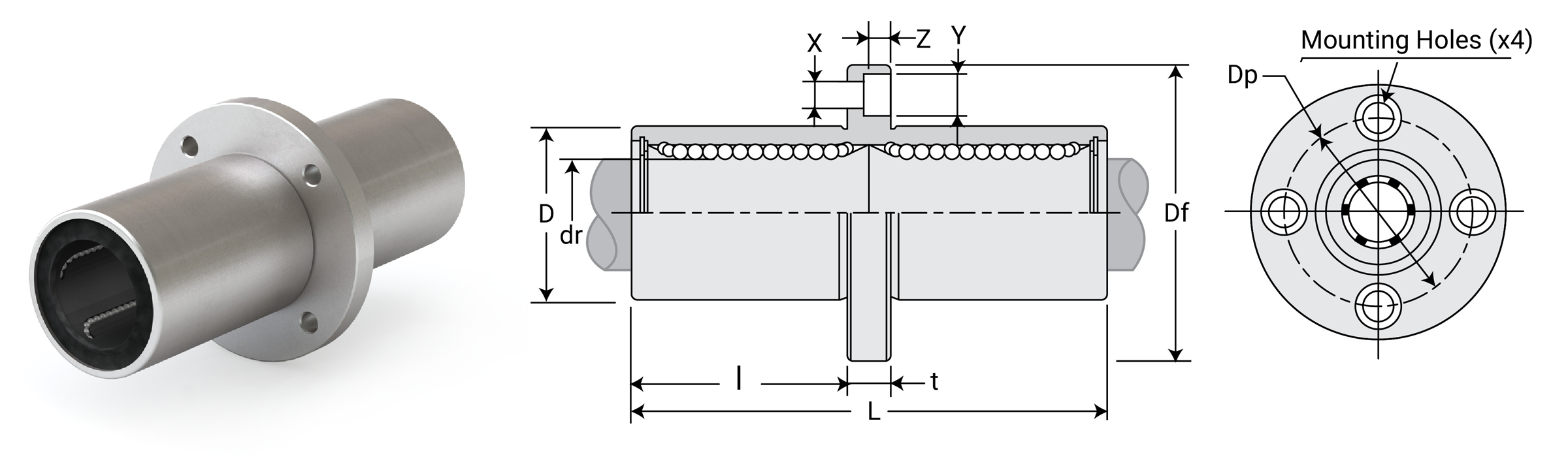
Dimensional Information
| Part No. Standard Polymer Cage |
Nominal Diameter | Ball Circuit | Weight G |
Major Dimensions & Tolerances | |||||
|---|---|---|---|---|---|---|---|---|---|
| Size mm |
dr mm |
Tolerance μm |
D mm |
Tolerance μm |
L mm |
Tolerance μm |
|||
| EPFC8G | 8 | 8 | +9/-1 | 4 | 59 | 16 | 0/-13 | 45 | ±300 |
| EPFC12G | 12 | 12 | +9/-1 | 4 | 110 | 22 | 0/-16 | 61 | ±300 |
| EPFC16G | 16 | 16 | +11/-1 | 5 | 160 | 26 | 0/-16 | 68 | ±300 |
| EPFC20G | 20 | 20 | +11/-1 | 5 | 260 | 32 | 0/-19 | 80 | ±300 |
| EPFC25G | 25 | 25 | +13/-2 | 6 | 540 | 40 | 0/-19 | 112 | ±300 |
| EPFC30G | 30 | 30 | +13/-2 | 6 | 815 | 47 | 0/-19 | 123 | ±300 |
| EPFC40G | 40 | 40 | +16/-4 | 6 | 1805 | 62 | 0/-22 | 154 | ±300 |
| EPFC50G | 50 | 50 | +16/-4 | 6 | 2820 | 75 | 0/-22 | 192 | ±300 |
| Part No. Standard Polymer Cage |
Nominal Diameter | Major Dimensions & Tolerances – Flange | Load Ratings | |||||||||||
|---|---|---|---|---|---|---|---|---|---|---|---|---|---|---|
| Size mm |
dr mm |
Tolerance μm |
I mm |
Df mm |
T mm |
DP mm |
X mm |
Y mm |
Z mm |
Eccentricity µm |
Squareness µm |
Dynamic C N |
Static Co N |
|
| EPFC8G | 8 | 8 | +9/-1 | 20.5 | 32 | 5 | 24 | 3.5 | 6.5 | 3.1 | 15 | 15 | 421 | 804 |
| EPFC12G | 12 | 12 | +9/-1 | 27.5 | 42 | 6 | 32 | 4.5 | 8 | 4.1 | 15 | 15 | 813 | 1570 |
| EPFC16G | 16 | 16 | +11/-1 | 31 | 46 | 6 | 36 | 4.5 | 8 | 4.1 | 15 | 15 | 921 | 1780 |
| EPFC20G | 20 | 20 | +11/-1 | 36 | 54 | 8 | 43 | 5.5 | 9.3 | 5.1 | 17 | 17 | 1370 | 2740 |
| EPFC25G | 25 | 25 | +13/-2 | 52 | 62 | 8 | 51 | 5.5 | 9.3 | 5.1 | 17 | 17 | 1570 | 3140 |
| EPFC30G | 30 | 30 | +13/-2 | 56.5 | 76 | 10 | 62 | 6.6 | 11 | 6.1 | 17 | 17 | 2500 | 5490 |
| EPFC40G | 40 | 40 | +16/-4 | 69 | 98 | 13 | 80 | 9 | 14 | 8.1 | 20 | 20 | 3430 | 8040 |
| EPFC50G | 50 | 50 | +16/-4 | 89.5 | 112 | 13 | 94 | 9 | 14 | 8.1 | 20 | 20 | 6080 | 15900 |
⚠ Only certified Simplicity 60 Plus Shafting provides maximum bearing performance.
Linear Metric Ball Bearings
Compact Thin Wall
Ball Bearings – Compact Thin Wall KHP
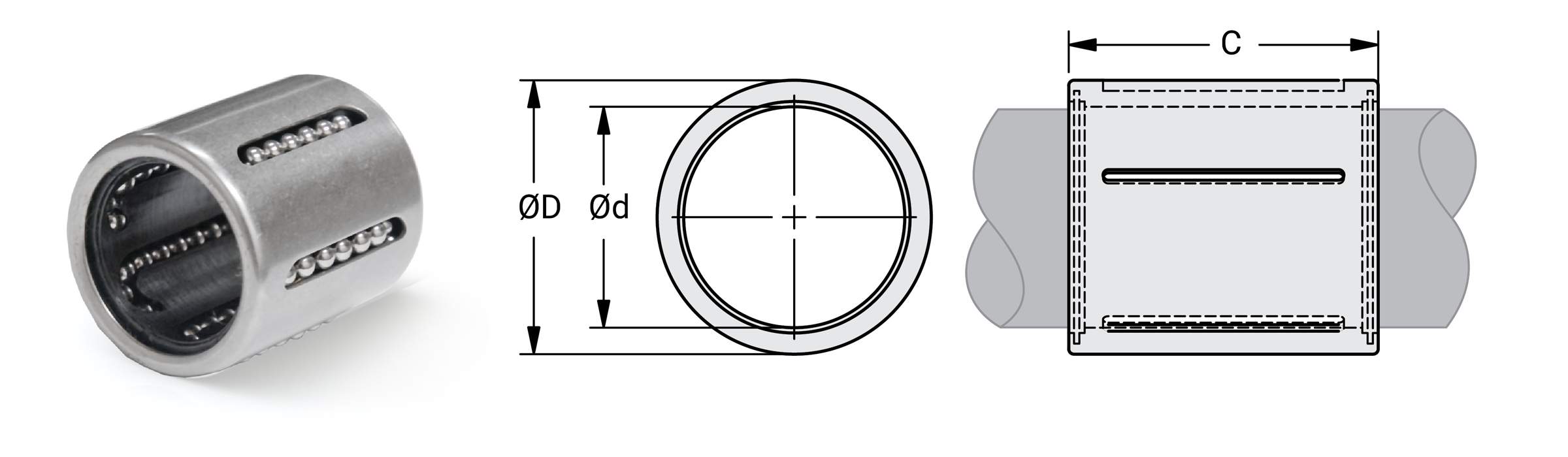
Dimensional Information
| Part No. | Dimensions | Load Rating | |||||||
|---|---|---|---|---|---|---|---|---|---|
| ØD mm |
Tolerance µm |
ØD mm |
Tolerance µm |
C mm |
Tolerance µm |
Weight G |
Dynamic C N |
Static Co N |
|
| KHP6 | 6 | 0/+12 | 12 | -11/0 | 22 | -520/0 | 7 | 400 | 239 |
| KHP8 | 8 | 0/+15 | 15 | -11/0 | 24 | -520/0 | 12 | 435 | 280 |
| KHP10 | 10 | 0/+15 | 17 | -11/0 | 26 | -520/0 | 14.5 | 500 | 370 |
| KHP12 | 12 | 0/+18 | 19 | -13/0 | 28 | -520/0 | 18.5 | 620 | 510 |
| KHP14 | 14 | 0/+18 | 21 | -13/0 | 28 | -520/0 | 20.5 | 620 | 520 |
| KHP16 | 16 | 0/+18 | 24 | -13/0 | 30 | -520/0 | 27.5 | 800 | 620 |
| KHP20 | 20 | 0/+21 | 28 | -13/0 | 30 | -520/0 | 32.5 | 950 | 790 |
| KHP25 | 25 | 0/+21 | 35 | -16/0 | 40 | -620/0 | 66 | 1990 | 1670 |
| KHP30 | 30 | 0/+21 | 40 | -16/0 | 50 | -620/0 | 95 | 2880 | 2700 |
| KHP40 | 40 | 0/+25 | 52 | -19/0 | 60 | -740/0 | 182 | 4400 | 4450 |
| KHP50 | 50 | 0/+25 | 62 | -19/0 | 70 | -740/0 | 252 | 5500 | 6300 |
⚠ Only certified Simplicity 60 Plus Shafting provides maximum bearing performance.
Metric Roller Pillow Blocks Bearings
Single Roller Pillow Block MSPB-OPN
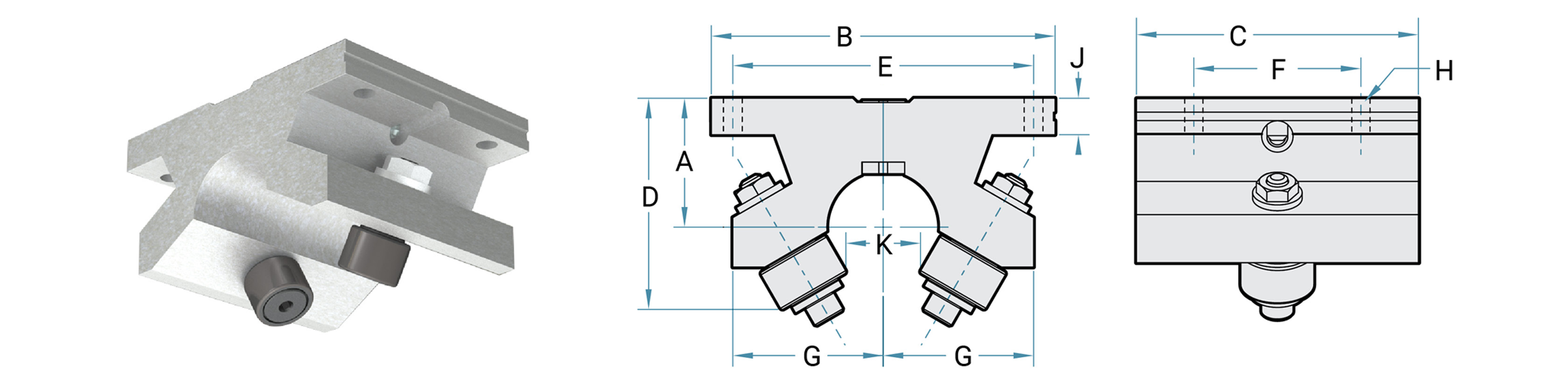
Dimensions and Load Ratings Metric Shafting
| Part No. | Shaft Diameter mm |
DYN. Load Rating N |
Weight N |
A ±0.08 mm |
B mm |
C mm |
D mm |
E ±0.13 mm |
F ±0.13 mm |
G mm |
H | J mm |
K mm |
|
|---|---|---|---|---|---|---|---|---|---|---|---|---|---|---|
| Bolt | Hole mm | |||||||||||||
| MSPB-16-OPN | 16 | 2224 | 226 | 22.2758 | 63.50 | 44.450 | 35.719 | 53.975 | 28.575 | 26.988 | #8 | 4.763 | 6.858 | 9.525 |
| MSPB-20-OPN | 20 | 2669 | 275 | 24.2824 | 69.85 | 47.625 | 39.688 | 60.325 | 31.750 | 26.988 | #8 | 4.763 | 7.620 | 11.113 |
| MSPB-25-OPN | 25 | 4248 | 453 | 29.9466 | 82.55 | 66.675 | 50.800 | 73.025 | 44.450 | 34.925 | #10 | 5.558 | 9.144 | 17.463 |
| MSPB-30-OPN | 30 | 6228 | 907 | 37.2110 | 101.60 | 85.725 | 65.088 | 88.900 | 50.800 | 44.450 | #10 | 5.558 | 10.770 | 20.638 |
Double Roller Pillow Block MDPB-OPN
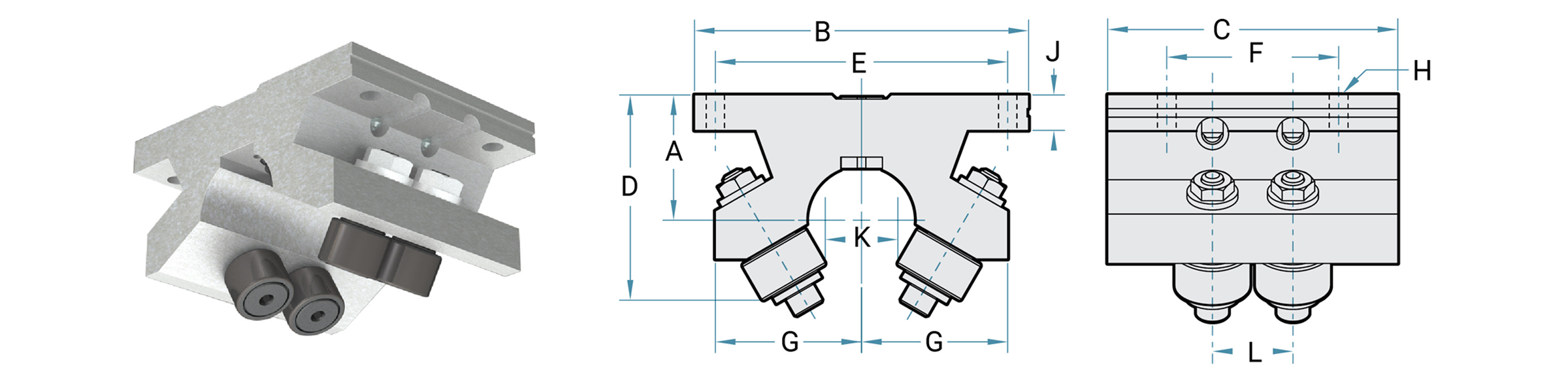
Dimensions and Load Ratings Metric Shafting
| Part No. | Shaft Diameter mm |
DYN. Load Rating N |
Weight N |
A ±0.08 mm |
B mm |
C mm |
D mm |
E ±0.13 mm |
F ±0.13 mm |
G mm |
H | J mm |
K mm |
L mm |
|
|---|---|---|---|---|---|---|---|---|---|---|---|---|---|---|---|
| Bolt | Hole mm | ||||||||||||||
| MDPB-16-OPN | 16 | 4448 | 317 | 22.2758 | 63.50 | 63.500 | 35.719 | 53.975 | 50.80 | 26.988 | #8 | 4.763 | 6.858 | 9.525 | 14.2748 |
| MDPB-20-OPN | 20 | 5338 | 362 | 24.2824 | 69.85 | 66.675 | 39.688 | 60.325 | 31.75 | 26.988 | #8 | 4.763 | 7.620 | 11.113 | 14.2748 |
| MDPB-25-OPN | 25 | 8496 | 544 | 29.9466 | 82.55 | 66.675 | 50.800 | 73.025 | 44.45 | 34.925 | #10 | 5.558 | 9.144 | 17.463 | 18.2880 |
| MDPB-30-OPN | 30 | 12455 | 360 | 37.2110 | 101.60 | 85.725 | 65.088 | 88.900 | 50.80 | 44.450 | #10 | 5.558 | 10.770 | 20.638 | 23.7998 |
Twin Roller Pillow Block MTWN-OPN
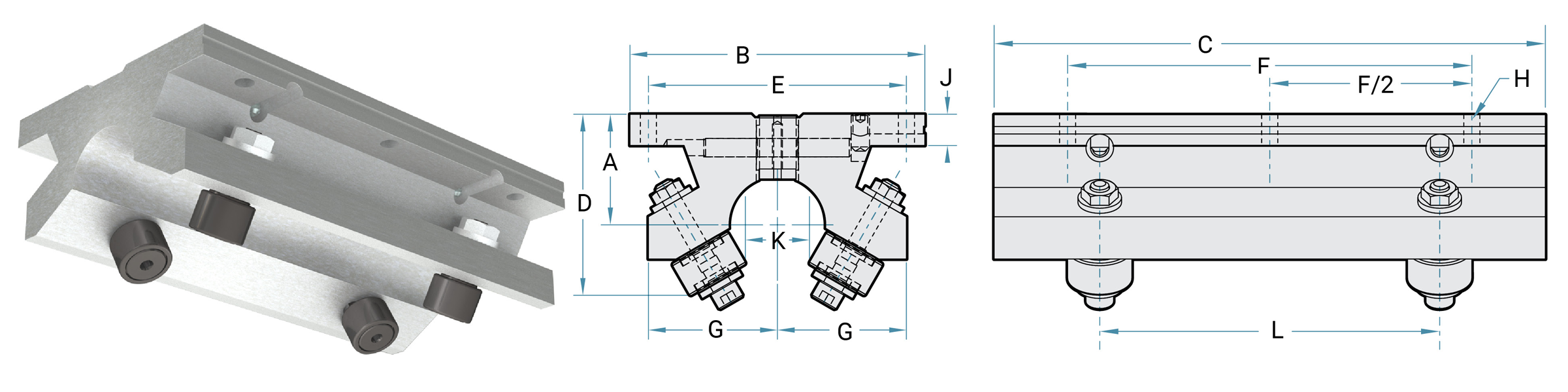
Dimensions and Load Ratings Metric Shafting
| Part No. | Shaft Diameter mm |
DYN. Load Rating N |
Weight N |
A ±0.08 mm |
B mm |
C mm |
D mm |
E ±0.13 mm |
F ±0.13 mm |
G mm |
H | J mm |
K mm |
L mm |
|
|---|---|---|---|---|---|---|---|---|---|---|---|---|---|---|---|
| Bolt | Hole mm | ||||||||||||||
| MTWN-16-OPN | 16 | 4448 | 454 | 22.2758 | 63.50 | 101.6 | 35.719 | 53.975 | 76.2 | 26.988 | #8 | 4.763 | 6.858 | 9.53 | 53.975 |
| MTWN-20-OPN | 20 | 5338 | 544 | 24.2824 | 69.85 | 114.3 | 39.688 | 60.325 | 88.9 | 26.988 | #8 | 4.763 | 7.620 | 11.11 | 63.500 |
| MTWN-25-OPN | 25 | 8496 | 1043 | 29.9466 | 82.55 | 152.4 | 50.800 | 73.025 | 114.3 | 34.925 | #10 | 5.558 | 9.144 | 17.46 | 95.250 |
| MTWN-30-OPN | 30 | 12455 | 1995 | 37.2110 | 101.60 | 190.5 | 65.088 | 88.900 | 139.7 | 44.450 | #10 | 5.558 | 10.770 | 20.64 | 117.475 |
Metric Round Shafting Steel
& Stainless Steel
Simplicity 60 Plus® Shafting
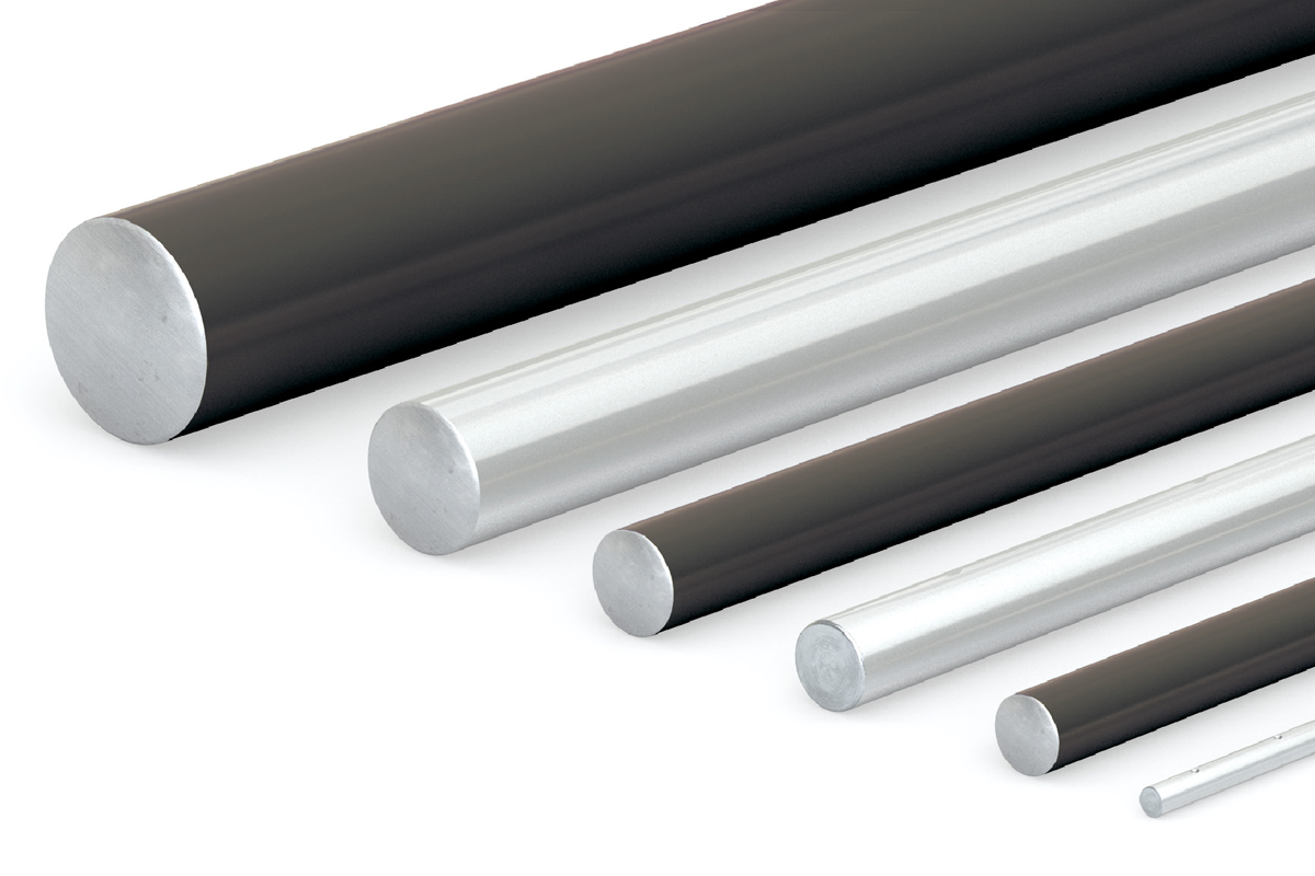
PBC Linear® formulated a linear shaft designed specifically for optimal bearing performance – 60 Plus Shafting. Advanced process capabilities maintain the ideal surface finish for linear bearings resulting in the longest life and highest performing shaft-to-bearing combination available:
- Optimized surface finish
- Faster break-in and better Frelon® transfer for plain bearings
- Longest life possible, less down time, and maintenance
- Straight to within 0.001" to 0.002" per foot cumulative, except on 3/8" diameter and smaller
Metric Shaft Part • Numbering Chart
| Class | Diameter | Material | Length | Type | ||
| NIL | 03 | SS | - | 010.000 | - | CM |
ClassNIM = Metric Shaft (Steel) NIPDM = Metric Predrill (Steel) CCM = Feather Metric (Aluminum) CCMDL = Feather Metric Predrill (Aluminum) SRM = Metric Support Rail (Aluminum) SRAM = Metric Support Rail Assembly (Aluminum) LSRM = Metric Low Support Rail (Steel) LSGM = Metric Low Support Rail Assembly (Steel) Diameter04 = 4 mm 05 = 5 mm 06 = 6 mm 08 = 8 mm 10 = 10 mm 12 = 12 mm 16 = 16 mm 20 = 20 mm 25 = 25 mm 30 = 30 mm 40 = 40 mm 50 = 50 mm 60 = 60 mm 80 = 80 mm Shaft MaterialBLANK = 1060 CS SS = 440 SS SS420 = 420 SS SS316 = 316 SS* ** CP = Chrome plate** AR = Armoloy** * 300 Series available in most diameters ** Available as special quotes Shaft LengthMillimeter - 0000 SpecialCM = Custom Machine SL = Specified Length |
Note: Chrome will have a guaranteed thickness of 0.0001" to 0.0005". Chrome thickness will be in addition to the catalog diameter of the shaft.
Sample Part Numbers
NIM20SS-0300-SL
Stainless Steel (SS) 20 mm diameter and 300 mm long
CCM12-0150-SL
Feather metric 12 mm diameter and 150 mm long
Online Configurator
Metric Round Shafting RC60 Steel
& Stainless Steel
RC60 Steel Solid Shafting NIM
- RC 60 Plus case hardened steel shafting
- Optimized for Simplicity® bearings and linear ball bearings
- Available cut-to-length or full lengths
- Length tolerance:
- 4 mm – 30 mm shaft = +/- 0.8 mm
- 40 mm – 50 mm shaft = +/- 1.6 mm
- 60 mm – 80 mm shaft = +/- 3.2 mm
- Joinable for longer lengths
- Available as solid shafting or pre-drilled

| Part No. | Nominal Dia. mm |
Dia. Tolerance mm |
MAX Length mm |
MIN Hardness Depth mm |
Weight Kg/M |
|
|---|---|---|---|---|---|---|
| MIN | MAX | |||||
| NIM04-xxxx | 4 | 3.987 | 4 | 6400 | 0.69 | 0.10 |
| NIM05-xxxx | 5 | 4.987 | 5 | 6400 | 0.69 | 0.15 |
| NIM06-xxxx | 6 | 5.987 | 6 | 6400 | 0.69 | 0.23 |
| NIM08-xxxx | 8 | 7.987 | 8 | 6400 | 0.69 | 0.39 |
| NIM10-xxxx | 10 | 9.987 | 10 | 6400 | 0.69 | 0.62 |
| NIM12-xxxx | 12 | 11.987 | 12 | 3900 | 1.02 | 0.89 |
| NIM16-xxxx | 16 | 15.987 | 16 | 3900 | 1.02 | 1.57 |
| NIM20-xxxx | 20 | 19.987 | 20 | 3900 | 1.52 | 2.45 |
| NIM25-xxxx | 25 | 24.987 | 25 | 4300 | 2.03 | 3.80 |
| NIM30-xxxx | 30 | 29.987 | 30 | 3900 | 2.03 | 5.50 |
| NIM40-xxxx | 40 | 39.984 | 40 | 3900 | 2.03 | 9.80 |
| NIM50-xxxx | 50 | 49.984 | 50 | 3900 | 2.54 | 15.30 |
| NIM60-xxxx | 60 | 59.981 | 60 | 3900 | 2.54 | 22.20 |
| NIM80-xxxx | 80 | 79.981 | 80 | 3550 | 2.54 | 39.50 |
Notes:
(1) Specify length in part number using millimeters. Example: for 25 mm shafting total length 900 mm = NIM25-0900.
(2) Surface finish bearing recommended 8 Ra.
440 & 420 Stainless Steel Solid Shafting NIMxxSS & NIMxxSS420
- 440 & 420 stainless steel RC 50 Plus™ hardness
- Optimized for Simplicity bearings and linear ball bearings
- Available cut-to-length or random lengths
- Length tolerance:
- 4 mm – 30 mm shaft = +/- 0.8 mm
- 40 mm – 50 mm shaft = +/- 1.6 mm
- 60 mm – 80 mm shaft = +/- 3.2 mm
- Joinable for longer lengths
- Available as solid shafting or pre-drilled
| >Part No. | Nominal Size mm |
Dia. Tolerance mm |
MAX Length mm |
MIN Hardness Depth mm |
Weight Kg/M |
||
|---|---|---|---|---|---|---|---|
| 440 SS | 420 SS | MIN | MAX | ||||
| NIM04SS-xxxx | NIM04SS420-xxxx | 4 | 3.987 | 4 | 6400 | 0.69 | 0.10 |
| NIM05SS-xxxx* | NIM05SS420-xxxx* | 5 | 4.987 | 5 | 6400 | 0.69 | 0.15 |
| NIM06SS-xxxx | NIM06SS420-xxxx | 6 | 5.987 | 6 | 6400 | 0.69 | 0.23 |
| NIM08SS-xxxx | NIM08SS420-xxxx | 8 | 7.987 | 8 | 6400 | 0.69 | 0.39 |
| NIM10SS-xxxx | NIM10SS420-xxxx | 10 | 9.987 | 10 | 6400 | 0.69 | 0.62 |
| NIM12SS-xxxx | NIM12SS420-xxxx | 12 | 11.987 | 12 | 3900 | 1.02 | 0.89 |
| NIM16SS-xxxx | NIM16SS420-xxxx | 16 | 15.987 | 16 | 3900 | 1.02 | 1.57 |
| NIM20SS-xxxx | NIM20SS420-xxxx | 20 | 19.987 | 20 | 3900 | 1.52 | 2.45 |
| NIM25SS-xxxx | NIM25SS420-xxxx | 25 | 24.987 | 25 | 4300 | 2.03 | 3.80 |
| NIM30SS-xxxx | NIM30SS420-xxxx | 30 | 29.987 | 30 | 3900 | 2.03 | 5.50 |
| NIM40SS-xxxx | NIM40SS420-xxxx | 40 | 39.984 | 40 | 3900 | 2.03 | 22.20 |
| NIM50SS-xxxx | NIM50SS420-xxxx | 50 | 49.984 | 50 | 3900 | 2.54 | 39.50 |
*Limited availability on NIM05SS, please contact factory.
Metric Round Shafting Stainless Steel
& Ceramic Coated
Pre-Drilled & Tapped
Steel NIPDM • 440 Stainless Steel NIPDMxxSS • 420 Stainless Steel
Steel NIPDM • 440 Stainless Steel NIPDMxxSS • 420 Stainless Steel
NIPDMxxSS420
| Part No. | Nominal Dia. mm |
Dia. Tolerance mm |
Standard Hole Spacing | Thread | MAX Length mm |
Weight Kg/M |
||||
|---|---|---|---|---|---|---|---|---|---|---|
| Steel | 440 SS | 420 SS | MIN | MAX | X | Y | ||||
| NIPDM12-xxxx | NIPDM12SS-xxxx | NIPDM12SS420-xxxx | 12 | 11.9888 | 12 | 120 | 60 | M4 x .7 | 4597 | 0.89 |
| NIPDM16-xxxx | NIPDM16SS-xxxx | NIPDM16SS420-xxxx | 16 | 15.9893 | 16 | 150 | 75 | M5 x .8 | 4597 | 1.57 |
| NIPDM20-xxxx | NIPDM20SS-xxxx | NIPDM20SS420-xxxx | 20 | 19.9873 | 20 | 150 | 75 | M6 x 1.0 | 4597 | 2.45 |
| NIPDM25-xxxx | NIPDM25SS-xxxx | NIPDM25SS420-xxxx | 25 | 24.9885 | 25 | 200 | 100 | M8 x 1.25 | 4902 | 3.80 |
| NIPDM30-xxxx | NIPDM30SS-xxxx | NIPDM30SS420-xxxx | 30 | 29.9872 | 30 | 200 | 100 | M10 x 1.5 | 4597 | 5.50 |
| NIPDM40-xxxx | NIPDM40SS-xxxx | NIPDM40SS420-xxxx | 40 | 39.9872 | 40 | 200 | 100 | M10 x 1.5 | 4496 | 9.80 |
| NIPDM50-xxxx | NIPDM50SS-xxxx | NIPDM50SS420-xxxx | 50 | 49.9846 | 50 | 200 | 100 | M12 x 1.75 | 4496 | 15.30 |
Notes:
(1) Specify length in part number using mm. Example: for 12 mm shafting total length 97 mm = NIPDM12-0097.
(2) Customer specifies 'y' dimension, if different than standard. Hole-to-hole tolerance = +/-.015".
(3) Consult factory for chrome plated, 303, or 316 stainless steel shafting.

Ceramic Coated
- Aluminum alloy base material
- RC 70 ceramic coated finish
- Designed to run with Simplicity® FrelonGOLD® lined bearings
- Interchanges with solid and pre-drilled shafting
- Non-magnetic and vibration resistant
- Weld splatter, paints, and contaminants will not stick
- NOT compatible with linear ball bearings
- Length tolerance
- 4 mm – 30 mm shaft = +/- 0.8 mm
- 40 mm – 50 mm shaft = +/- 1.6 mm
- 60 mm – 80 mm shaft = +/- 3.2 mm
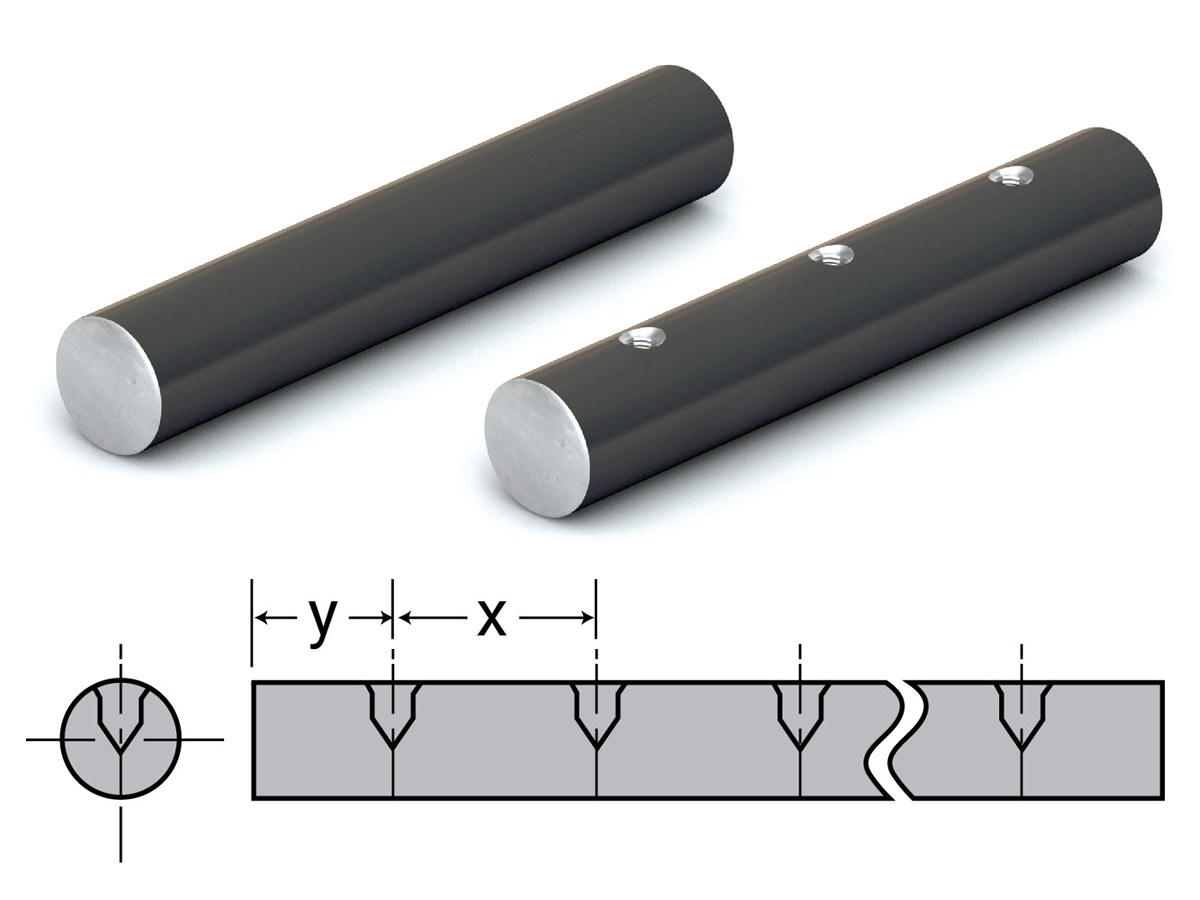
Solid Shafting CCM
| Part No. | Nominal Dia. mm |
Dia. Tolerance mm |
MAX Length mm |
Weight Kg/M |
|
|---|---|---|---|---|---|
| MIN | MAX | ||||
| CCM06-xxxx | 6 | 5.992 | 6 | 3500 | 0.04 |
| CCM08-xxxx | 8 | 7.991 | 8 | 3500 | 0.07 |
| CCM10-xxxx | 10 | 9.991 | 10 | 3500 | 0.10 |
| CCM12-xxxx | 12 | 11.989 | 12 | 3500 | 0.15 |
| CCM16-xxxx | 16 | 15.989 | 16 | 3500 | 0.26 |
| CCM20-xxxx | 20 | 19.987 | 20 | 3500 | 0.41 |
| CCM25-xxxx | 25 | 24.987 | 25 | 3500 | 0.63 |
| CCM30-xxxx | 30 | 29.987 | 30 | 3500 | 0.92 |
| CCM40-xxxx | 40 | 39.984 | 40 | 3500 | 1.63 |
| CCM50-xxxx | 50 | 49.984 | 50 | 3500 | 2.55 |
Notes:
(1) Specify length in part number using inches.
Example: for 1/2" shafting total length 36" long = CC08-036.000.
(2) Ends of cut-to-length shafting are not coated.
(3) Fully coated shafting is available on special request.
Pre-Drilled & Tapped CCMDL
| Part No. | Nominal Dia. mm |
Dia. Tolerance mm |
Standard Hole Spacing | Thread | MAX Length mm |
Weight Kg/M |
||
|---|---|---|---|---|---|---|---|---|
| MIN | MAX | X | Y | |||||
| CCMDL08-xxxx | 8 | 7.991 | 8 | 101.6 | 50.8 | M2 x .4 | 3500 | 0.07 |
| CCMDL10-xxxx | 10 | 9.991 | 10 | 101.6 | 50.8 | M3 x .5 | 3500 | 0.10 |
| CCMDL12-xxxx | 12 | 11.989 | 12 | 120 | 60 | M4 x .7 | 3500 | 0.15 |
| CCMDL16-xxxx | 16 | 15.989 | 16 | 150 | 75 | M5 x .8 | 3500 | 0.26 |
| CCMDL20-xxxx | 20 | 19.987 | 20 | 150 | 75 | M6 x 1.0 | 3500 | 0.41 |
| CCMDL25-xxxx | 25 | 24.987 | 25 | 200 | 100 | M8 x 1.25 | 3500 | 0.63 |
| CCMDL30-xxxx | 30 | 29.987 | 30 | 200 | 100 | M10 x 1.5 | 3500 | 0.92 |
Notes:
(1) Specify length in part number using mm. Example: for 10 mm shafting total length 97 mm = CCMDL08-0097.
(2) Ends of cut-to-length shafting are not coated.
(3) Fully coated shafting is available on special request.
(4) Customer specifies 'y' dimension, if different than standard.
Metric Shafting Rail Assemblies
Rail Assembly – Aluminum Support Rail SRA
- Two piece assembly RC60 steel shaft and aluminum support rail standard
- Other shaft materials – 440 stainless steel, 420 stainless steel, and ceramic coated aluminum
- No coating
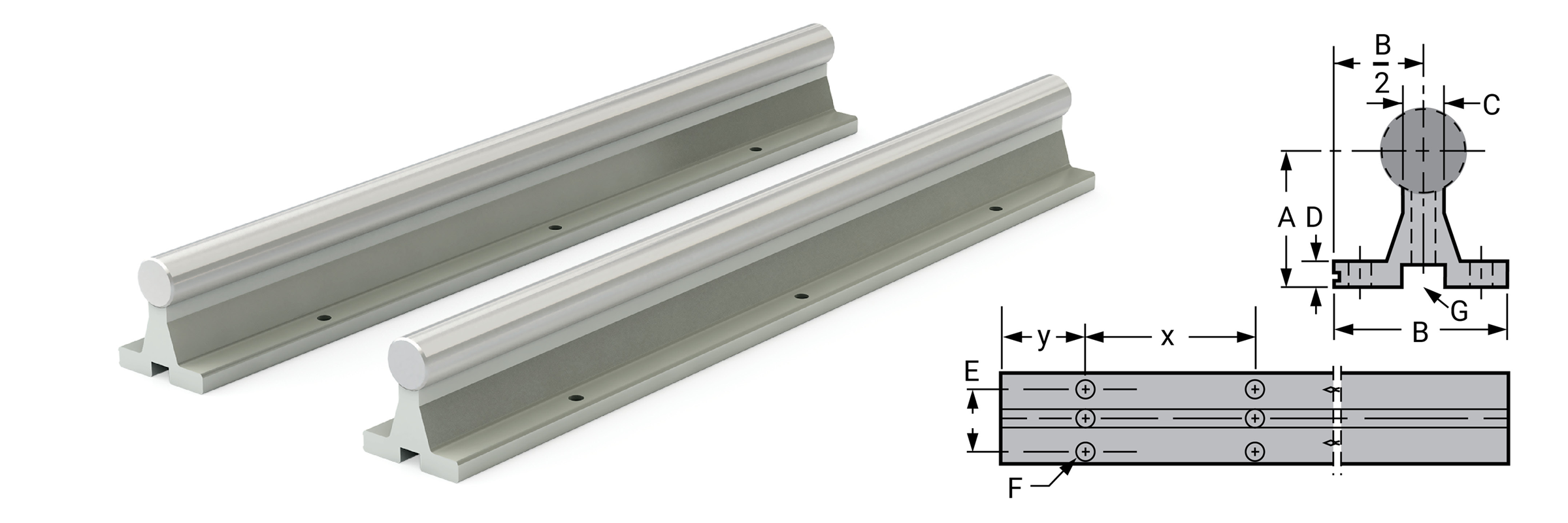
| Part No.* | Nominal Dia. MM |
Diameter Tolerance | A ±0.05 |
B | C | D | E | F Hole Size |
Standard Hole Spacing |
Weight Kg/M |
||||
|---|---|---|---|---|---|---|---|---|---|---|---|---|---|---|
| Shaft Size | Material** | Length | MIN | MAX | X | Y | ||||||||
| SRAM12 | ______ | -_ _ _ _-SL | 12 | 11.9888 | 12 | 28.00 | 43.00 | 6.60 | 4.76 | 29 | M4 | 120 | 60 | 1.80 |
| SRAM16 | ______ | -_ _ _ _-SL | 16 | 15.9893 | 16 | 28.50 | 48.00 | 7.94 | 6.35 | 33 | M5 | 150 | 75 | 2.59 |
| SRAM20 | ______ | -_ _ _ _-SL | 20 | 19.9873 | 20 | 38.00 | 56.00 | 9.53 | 6.35 | 37 | M6 | 150 | 75 | 3.61 |
| SRAM25 | ______ | -_ _ _ _-SL | 25 | 24.9885 | 25 | 42.00 | 60.00 | 12.70 | 6.35 | 42 | M8 | 200 | 100 | 5.86 |
| SRAM30 | ______ | -_ _ _ _-SL | 30 | 29.9872 | 30 | 53.00 | 74.00 | 14.29 | 7.94 | 51 | M10 | 200 | 100 | 8.80 |
| SRAM40 | ______ | -_ _ _ _-SL | 40 | 39.9872 | 40 | 64.00 | 78.00 | 17.46 | 9.53 | 55 | M10 | 200 | 100 | 12.70 |
| SRAM50 | ______ | -_ _ _ _-SL | 50 | 49.9846 | 50 | 70.00 | 82.00 | 20.30 | 10.50 | 62 | M12 | 200 | 100 | 21.98 |
*Part Numbers are complete when Material and Length are added.
Default material is 1060 steel when no Material is specified.
**For other steel options add below code into Material location:
CC Ceramic Coated Shafting
SS 440 Stainless Steel
SS420 420 Stainless Steel
Example 1: The Complete Part Number for a 1 inch diameter
440 Stainless Steel shaft of 240 mm is SRAM16SS-0240-SL
Notes: Specify length in part number using inches. Example: for 20 mm shafting total length 914 mm long = SRAM20-0914-SL. Customer specifies 'y' dimension, if different than standard.
Contact PBC Linear for other available hole patterns.
Support Rail – Aluminum SR & SR_PD
Non-Drilled (SRM)
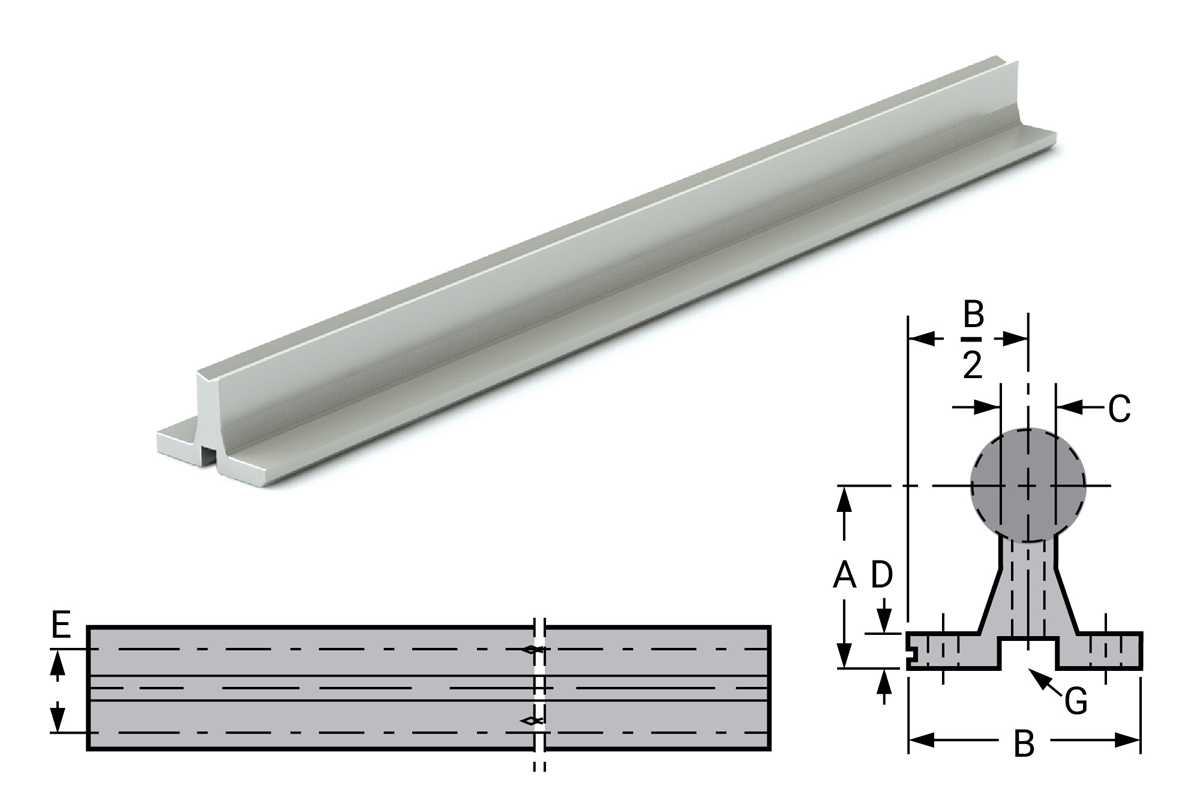
Pre-Drilled (SRMxxPD)

| Part No. | Nominal Dia. MM |
A ±0.05 |
B | C | D | E | H Hole Size |
G Mounting Bolt Size |
MAX Length +0/-3.2 mm |
Standard Hole Spacing |
Weight Kg/M |
|||
|---|---|---|---|---|---|---|---|---|---|---|---|---|---|---|
| Non-Drilled | Pre-Drilled | Screw | Fastener Length mm | X | Y | |||||||||
| SRM12 | SRM12PD | 12 | 28.00 | 43.00 | 6.60 | 4.76 | 29 | M4 | M4 x 0.70 | 20 | 1200 | 120 | 60 | 0.803 |
| SRM16 | SRM16PD | 16 | 28.50 | 48.00 | 7.94 | 6.35 | 33 | M5 | M5 x 0.80 | 20 | 1200 | 150 | 75 | 1.040 |
| SRM20 | SRM20PD | 20 | 38.00 | 56.00 | 9.53 | 6.35 | 37 | M6 | M6 x 1.00 | 30 | 1200 | 150 | 75 | 1.380 |
| SRM25 | SRM25PD | 25 | 42.00 | 60.00 | 12.70 | 6.35 | 42 | M8 | M8 x 1.25 | 40 | 1200 | 200 | 100 | 1.860 |
| SRM30 | SRM30PD | 30 | 53.00 | 74.00 | 14.29 | 7.94 | 51 | M10 | M10 x 1.5 | 40 | 1200 | 200 | 100 | 2.590 |
| SRM40 | SRM40PD | 40 | 64.00 | 78.00 | 17.46 | 9.53 | 55 | M10 | M10 x 1.5 | 50 | 1200 | 200 | 100 | 3.750 |
| SRM50 | SRM50PD | 50 | 70.00 | 82.00 | 20.30 | 10.50 | 62 | M12 | M12 x 1.75 | 70 | 1200 | 200 | 100 | 6.110 |
Notes:
(1) Specify length in part number. Example: for 12 mm shafting support rail to 609 mm length = SRM12-0609 (Aluminum alloy construction, no coating).
(2) Shafts and support rails sold separately. Customer specifies 'y' dimension. Shaft rails and assemblies are available in long lengths, consult factory
Metric Shafting Low Support Rails
Low Support Rail – Steel LSRM
The AISI C-1018 steel LSRM shaft support is a low support rail with a reduced footprint, and 40% lower profile than other support rails. This is an excellent choice for applications requiring compact low shaft support. The standard length for LSRM type supports is 1200 mm.
- No coating
- Length tolerance +0 mm/3 mm.

| Part No. | Assembly Part No. |
Shaft Dia. mm |
A ±0.05 |
B ±0.05 |
C ±0.05 |
D Hole Size |
Standard Hole Spacing |
Weight per 1219mm (approximate) Kg |
Assembly Weight per 1200mm (approximate) Kg |
|
|---|---|---|---|---|---|---|---|---|---|---|
| X | Y | |||||||||
| LSRM12 LSRM12PD |
LSRAM-12 | 12 | 13.91 | 9.40 | 8.66 | M4 | 120 | 60 | 0.599 | 1.79 |
| LSRM16 LSRM16PD |
LSRAM-16 | 16 | 17.54 | 11.43 | 10.46 | M5 | 150 | 75 | 0.884 | 2.76 |
| LSRM20 LSRM20PD |
LSRAM-20 | 20 | 19.58 | 12.95 | 10.46 | M6 | 150 | 75 | 1.020 | 3.61 |
| LSRM25 LSRM25PD |
LSRAM-25 | 25 | 25.22 | 17.53 | 14.22 | M8 | 200 | 100 | 1.980 | 5.86 |
| LSRM30 LSRM30PD |
LSRAM-30 | 30 | 29.26 | 19.81 | 15.9 | M10 | 200 | 100 | 2.480 | 8.80 |
| LSRM40 LSRM40PD |
LSRAM-40 | 40 | 35.96 | 23.62 | 17.86 | M10 | 200 | 100 | 3.340 | 12.70 |
| LSRM50 LSRM50PD |
LSRAM-50 | 50 | 44.02 | 29.97 | 21.46 | M12 | 200 | 100 | 5.030 | 21.98 |
How to order
- Available as cut to length options up to a max length of 3657 mm. Example: 1200 mm would be LSRM16-1200-SL.
- If standard mounting holes are required, specify low shaft rails with pre-drilled mounting holes by part number. For example, LSRM12PD. Hole sizes and spacings are shown in the table.
- If other than standard hole spacing is required, please provide drawings with all dimensions, tolerances, and quantity. With or without mounting holes, low shaft rails will be supplied in 1200 mm lengths when ordered by part number.
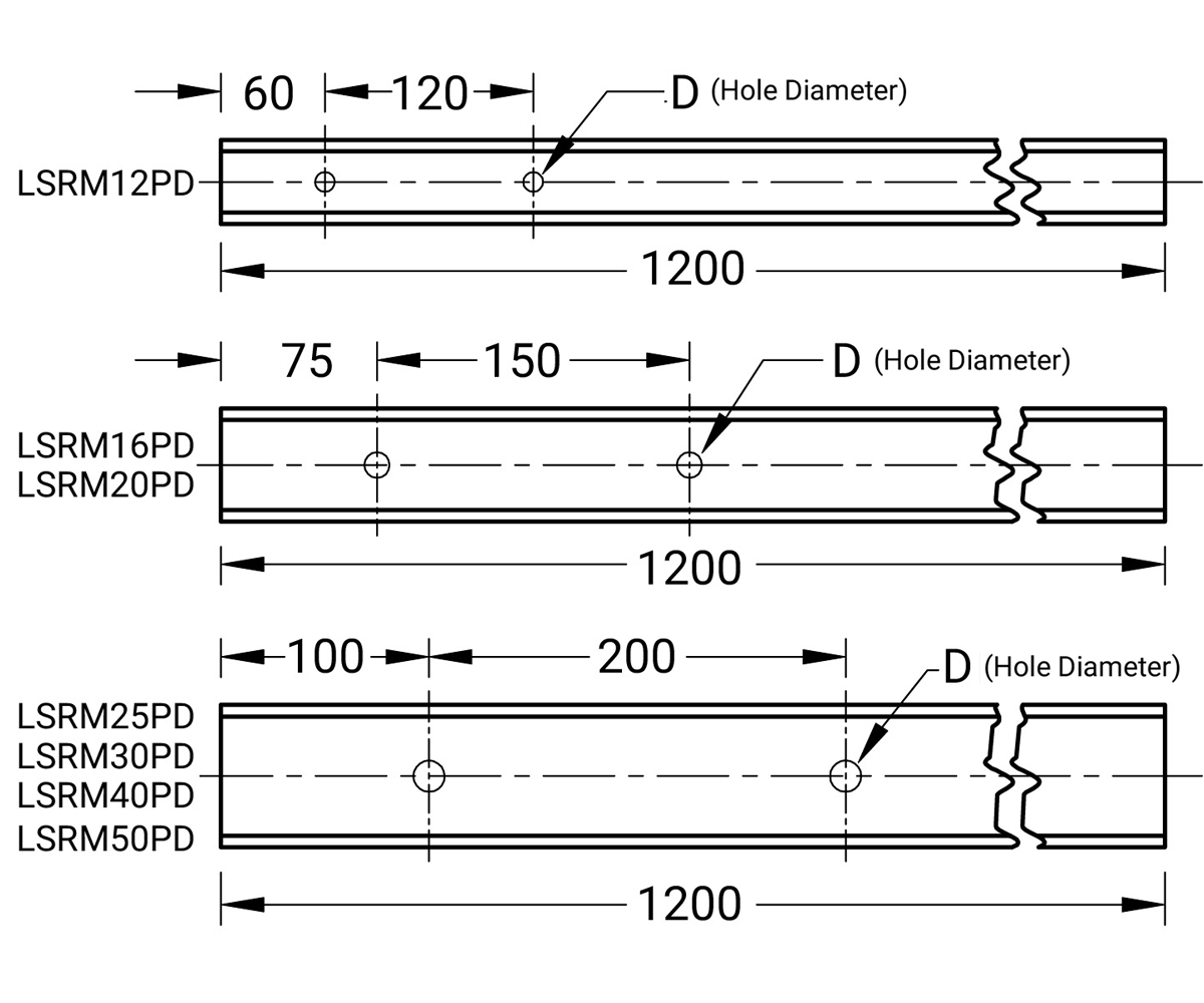
Low Support Rail & Shaft Set LSG
Precision case hardened and ground shaft, plus an LSR steel support rail, effectively doubles the life of the shaft by allowing it to be turned over for a fresh surface when wear becomes evident. Both sides of the shaft are counterbored so the shaft may be rotated 180°, and rebolted for use on the new side. This guide is sold as a two-piece set; the shaft and support are not assembled. The guide is then bolted down through the top of the shaft to reduce installation time. The shafts are also available in 400 series stainless steel. Drilled through and counterbored shafts may not be suitable for all linear bearings.
- No coating

| Part No. | Shaft Dia. mm |
H mm |
B mm |
Y mm |
X mm |
N mm |
Weight per in. Km |
|---|---|---|---|---|---|---|---|
| LSGM16 | 16 | 17.54 | 11.43 | 75 | 150 | #5 | 2.36 |
| LSGM20 | 20 | 19.58 | 12.95 | 75 | 150 | #6 | 3.05 |
| LSGM25 | 25 | 25.22 | 17.53 | 100 | 200 | #10 | 5.55 |
| LSGM30 | 30 | 29.26 | 19.81 | 100 | 200 | 5/16 | 8.11 |
| LSGM40 | 40 | 35.96 | 23.62 | 100 | 200 | 3/8 | 11.43 |
| LSGM50 | 50 | 44.02 | 29.97 | 100 | 200 | 1/2 | 19.98 |
Notes: Customer specifies 'y' dimension.
Simplicity JIS Metric Linear
Plain Bearings
Linear Plain Bearing FJ & FJN
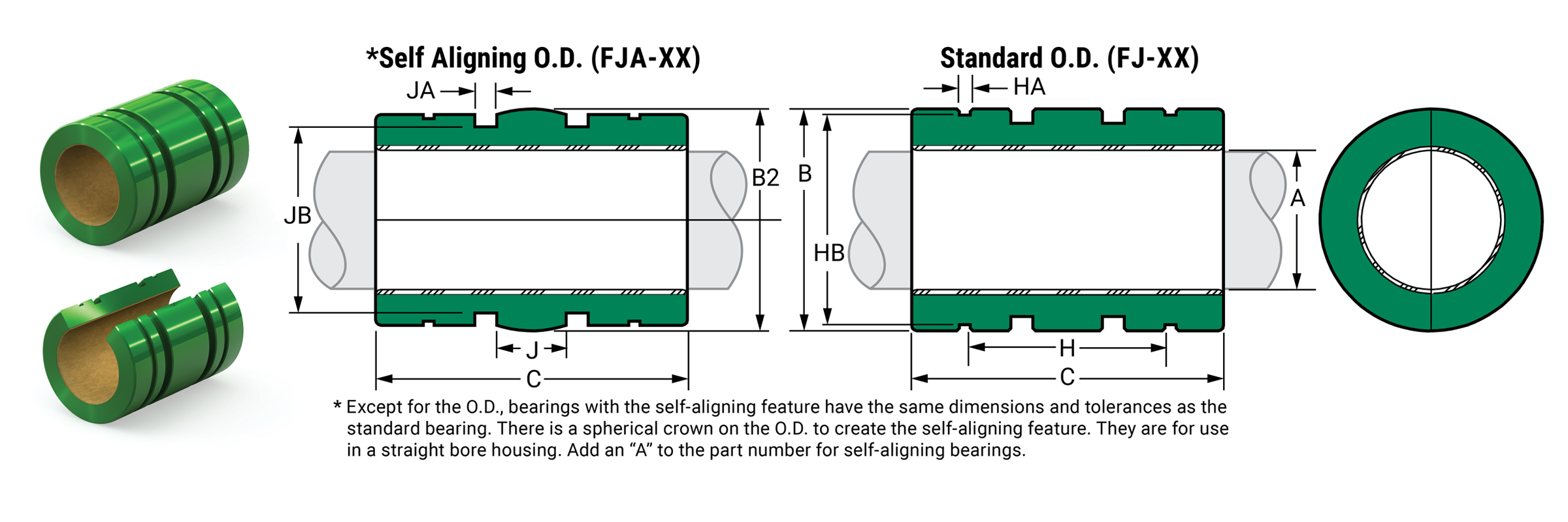
Dimensional Information
| Precision I.D. Series Similar to Preloaded Ball Bearing |
Compensated I.D. Series Allows Additional Running Clearance |
B Standard O.D. |
B2 Self-Aligning O.D. FJA |
C Length |
Concentric MAX |
Bearing Weight Kg. |
||||||||||
|---|---|---|---|---|---|---|---|---|---|---|---|---|---|---|---|---|
| Part No. | Nominal Size mm |
A Bearing I.D. |
Part No. | A Bearing I.D. |
||||||||||||
| Closed | Open | MIN | MAX | Closed | Open | MIN | MAX | MIN | MAX | MIN | MAX | MIN | MAX | |||
| FJ06 | N/A | 6 | 6.01 | 6.028 | FJC06 | FJCN06 | 6.06 | 6.078 | 11.989 | 12 | 11.943 | 11.968 | 18.619 | 19 | 0.0254 | 0.004 |
| FJH08 | FJHN08 | 8 | 8.013 | 8.035 | FJCH08 | FJCHN08 | 8.063 | 8.085 | 14.989 | 15 | 14.943 | 14.968 | 16.619 | 17 | 0.0254 | 0.005 |
| FJ08 | FJN08 | 8 | 8.013 | 8.035 | FJC08 | FJCN08 | 8.063 | 8.085 | 14.989 | 15 | 14.943 | 14.968 | 23.619 | 24 | 0.0254 | 0.008 |
| FJ10 | FJN10 | 10 | 10.013 | 10.035 | FJC10 | FJCN10 | 10.063 | 10.086 | 18.987 | 19 | 18.936 | 18.969 | 28.619 | 29 | 0.0254 | 0.015 |
| FJ12 | FJN12 | 12 | 12.016 | 12.043 | FJC12 | FJCN12 | 12.066 | 12.093 | 20.987 | 21 | 20.942 | 20.968 | 29.619 | 30 | 0.0254 | 0.018 |
| FJ13 | FJN13 | 13 | 13.016 | 13.043 | FJC13 | FJCN13 | 13.066 | 13.093 | 22.987 | 23 | 22.944 | 22.969 | 31.619 | 32 | 0.0254 | 0.024 |
| FJ16 | FJN16 | 16 | 16.016 | 16.043 | FJC16 | FJCN16 | 16.066 | 16.093 | 27.988 | 28 | 27.943 | 27.968 | 36.619 | 37 | 0.0254 | 0.039 |
| FJ20 | FJN20 | 20 | 20.02 | 20.053 | FJC20 | FJCN20 | 20.096 | 20.129 | 31.984 | 32 | 31.941 | 31.966 | 41.619 | 42 | 0.0254 | 0.052 |
| FJ25 | FJN25 | 25 | 25.02 | 25.053 | FJC25 | FJCN25 | 25.096 | 25.129 | 39.984 | 40 | 39.942 | 39.967 | 58.619 | 59 | 0.0254 | 0.119 |
| FJ30 | FJN30 | 30 | 30.02 | 30.053 | FJC30 | FJCN30 | 30.096 | 30.129 | 44.984 | 45 | 44.94 | 44.966 | 63.619 | 64 | 0.0254 | 0.149 |
| FJ35 | FJN35 | 35 | 35.02 | 35.053 | FJC35 | FJCN35 | 35.1 | 35.136 | 51.981 | 52 | 51.94 | 51.966 | 69.619 | 70 | 0.0254 | 0.212 |
| FJ38 | FJN38 | 38 | 38.025 | 38.064 | FJC38 | FJCN38 | 38.127 | 38.166 | 56.981 | 57 | 56.94 | 56.966 | 75.619 | 76 | 0.0254 | 0.284 |
| FJ40 | FJN40 | 40 | 40.025 | 40.064 | FJC40 | FJCN40 | 40.127 | 40.166 | 59.981 | 60 | 59.939 | 59.964 | 79.619 | 80 | 0.0254 | 0.333 |
| FJ50 | FJN50 | 50 | 50.025 | 50.064 | FJC50 | FJCN50 | 50.127 | 50.166 | 79.981 | 80 | 79.939 | 79.964 | 99.619 | 100 | 0.0254 | 0.823 |
| FJ60 | FJN60 | 60 | 60.03 | 60.076 | FJC60 | FJCN60 | 60.182 | 60.228 | 89.978 | 90 | 89.939 | 89.964 | 109.619 | 110 | 0.0254 | 1.024 |
| FJ80 | FJN80 | 80 | 80.03 | 80.076 | FJC80 | FJCN80 | 80.182 | 80.228 | 119.978 | 120 | 119.939 | 119.964 | 139.619 | 140 | 0.038 | 2.359 |
| FJ100 | FJN100 | 100 | 100.03 | 100.076 | FJC100 | FJCN100 | 100.182 | 100.228 | 149.975 | 150 | 149.936 | 149.962 | 174.619 | 175 | 0.051 | 4.651 |
| FJ120 | FJN120 | 120 | 120.035 | 120.089 | FJC120 | FJCN120 | 120.19 | 120.236 | 179.975 | 180 | 179.936 | 179.962 | 199.619 | 200 | 0.051 | 7.706 |
| FJ150 | FJN150 | 150 | 150.035 | 150.089 | FJC150 | FJCN150 | 150.19 | 150.236 | 209.971 | 210 | 209.934 | 209.959 | 239.619 | 240 | 0.051 | 11.104 |
Mounting Information
| Part No. | Nominal Size | H Between RET. Rings |
HA RET. Ring GRV. Width |
HB RET. Ring GRV. Dia. |
Ret. Ring Part No. JIS B 2904 |
J Between O'ring GRVS. |
JA O'ring GRV. Width |
JB O'ring GRV. Dia. |
Metric O'ring Size |
|
|---|---|---|---|---|---|---|---|---|---|---|
| Closed | Open | |||||||||
| FJ06 | N/A | 6 | 11.3 | 1.15 | 11.5 | STW-12 | 4.293 | 2.032 | 9.859 | 9.7 x 1.3 |
| FJH08 | FJHN08 | 8 | 9.2 | 1.15 | 14.3 | STW-15 | 2.540 | 2.362 | 12.243 | 12 x 1.7 |
| FJ08 | FJN08 | 8 | 15.2 | 1.15 | 14.3 | STW-15 | 7.493 | 2.362 | 12.243 | 12 x 1.7 |
| FJ10 | FJN10 | 10 | 19.3 | 1.35 | 18.0 | STW-19 | 9.500 | 2.362 | 15.700 | 15.5 x 2 |
| FJ12 | FJN12 | 12 | 20.3 | 1.35 | 20.0 | STW-20 | 10.490 | 2.362 | 18.546 | 18 x 1.5 |
| FJ13 | FJN13 | 13 | 20.3 | 1.35 | 22.0 | STW-23 | 11.481 | 2.362 | 20.544 | 20 x 1.5 |
| FJ16 | FJN16 | 16 | 23.2 | 1.65 | 26.6 | STW-28 | 11.100 | 3.556 | 23.978 | 23.5 x 2.5 |
| FJ20 | FJN20 | 20 | 27.2 | 1.65 | 30.3 | STW-32 | 15.977 | 3.556 | 27.864 | 27.5 x 2.5 |
| FJ25 | FJN25 | 25 | 37.2 | 1.85 | 38.0 | STW-40 | 19.990 | 3.556 | 35.865 | 35.5 x 2.5 |
| FJ30 | FJN30 | 30 | 40.7 | 1.85 | 42.5 | STW-45 | 22.479 | 3.556 | 40.843 | 40 x 2.5 |
| FJ35 | FJN35 | 35 | 44.8 | 2.20 | 49.0 | STW-52 | 25.984 | 4.115 | 46.200 | 46 x 3.5 |
| FJ38 | FJN38 | 38 | 54.3 | 2.20 | 54.5 | STW-58 | 28.499 | 4.115 | 51.200 | 51 x 3.5 |
| FJ40 | FJN40 | 40 | 56.1 | 2.20 | 57.0 | STW-60 | 29.997 | 4.115 | 54.225 | 53 x 3.5 |
| FJ50 | FJN50 | 50 | 68.6 | 2.70 | 76.5 | STW-80 | 39.980 | 4.750 | 74.193 | 73 x 3.5 |
| FJ60 | FJN60 | 60 | 78.7 | 3.15 | 86.5 | STW-90 | 44.983 | 7.036 | 81.738 | 81 x 5 |
| FJ80 | FJN80 | 80 | 97.2 | 4.15 | 116.0 | STW-120 | 59.995 | 7.137 | 111.727 | 111 x 5 |
| FJ100 | FJN100 | 100 | 117.2 | 4.15 | 145.0 | STW-150 | 74.981 | 7.137 | 141.199 | 140 x 5.3 |
| FJ120 | FJN120 | 120 | 150.3 | 4.15 | 175.0 | STW-180 | 89.992 | 7.137 | 171.740 | 170 x 5 |
| FJ150 | FJN150 | 150 | 160.3 | 5.15 | 204.0 | STW-210 | 104.978 | 7.137 | 201.193 | 200 x 5.3 |
Linear Plain Bearing FJ & FJN
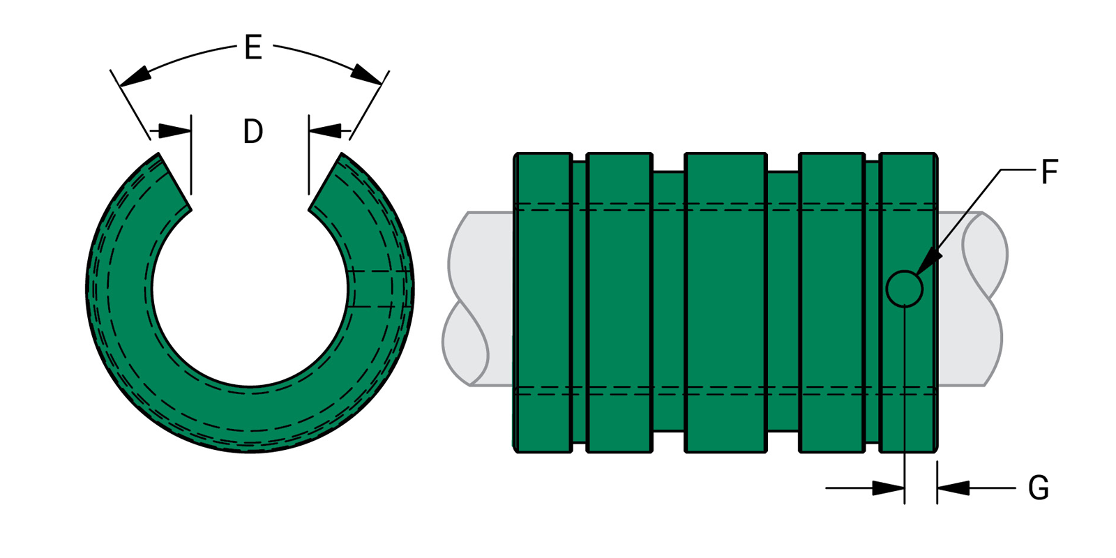
Open Dimensional Information
| Part No. | Nominal Size mm |
D Slot Width MIN. |
E Slot Angle |
F Ret. Hole Dia. |
G Ret. Hole Loc. |
Bearing Weight Kg. |
|
|---|---|---|---|---|---|---|---|
| Precision | Compensated | ||||||
| FJHN08 | FJHCN08 | 8 | 5.1 | 60 | 2.200 | 8.460 | 0.004 |
| FJN08 | FJCN08 | 8 | 5.1 | 60 | 2.200 | 11.940 | 0.006 |
| FJN10 | FJCN10 | 10 | 7.0 | 80 | 3.454 | 1.941 | 0.012 |
| FJN12 | FJCN12 | 12 | 8.0 | 80 | 3.454 | 1.941 | 0.014 |
| FJN13 | FJCN13 | 13 | 9.0 | 80 | 3.454 | 2.441 | 0.018 |
| FJN16 | FJCN16 | 16 | 11.0 | 80 | 3.454 | 3.019 | 0.030 |
| FJN20 | FJCN20 | 20 | 11.0 | 60 | 3.454 | 3.175 | 0.044 |
| FJN25 | FJCN25 | 25 | 12.0 | 50 | 3.454 | 3.175 | 0.102 |
| FJN30 | FJCN30 | 30 | 15.0 | 50 | 5.105 | 4.763 | 0.128 |
| FJN35 | FJCN35 | 35 | 17.0 | 50 | 5.105 | 4.763 | 0.182 |
| FJN38 | FJCN38 | 38 | 18.0 | 50 | 5.105 | 4.763 | 0.245 |
| FJN40 | FJCN40 | 40 | 20.0 | 50 | 5.105 | 4.763 | 0.286 |
| FJN50 | FJCN50 | 50 | 25.0 | 50 | 6.731 | 7.938 | 0.709 |
| FJN60 | FJCN60 | 60 | 30.0 | 50 | 6.731 | 7.938 | 0.882 |
| FJN80 | FJCN80 | 80 | 40.0 | 50 | 6.731 | 13.181 | 2.031 |
| FJN100 | FJCN100 | 100 | 50.0 | 50 | 6.731 | 14.500 | 4.005 |
| FJN120 | FJCN120 | 120 | 85.0 | 80 | 6.731 | 16.103 | 5.994 |
| FJN150 | FJCN150 | 150 | 105.0 | 80 | 6.731 | 17.350 | 8.637 |
Load & Speed Data
| Part No. | Effective Surface Area CM² |
MAX Static Load Kg Frelon® |
Effective Surface Area CM² |
MAX Static Load N Frelon |
||
|---|---|---|---|---|---|---|
| GOLD | J & W | GOLD | J & W | |||
| FJ06 | 1.1 | 528 | 264 | 1.14 | 2348 | 1174 |
| FJH08 | 1.4 | 630 | 315 | 1.40 | 2805 | 1402 |
| FJ08 | 1.9 | 890 | 445 | 1.90 | 3962 | 1981 |
| FJ10 | 2.9 | 1344 | 672 | 2.90 | 5982 | 2991 |
| FJ12 | 3.6 | 1666 | 833 | 3.60 | 7413 | 3707 |
| FJ13 | 4.0 | 1926 | 963 | 4.00 | 8570 | 4285 |
| FJ16 | 5.9 | 2741 | 1371 | 5.90 | 12199 | 6099 |
| FJ20 | 8.4 | 3887 | 1944 | 8.40 | 17298 | 8649 |
| FJ25 | 15.0 | 6827 | 3413 | 15.00 | 30379 | 15189 |
| FJ30 | 19.0 | 8885 | 4442 | 19.00 | 39538 | 19769 |
| FJ35 | 25.0 | 11340 | 5670 | 25.00 | 50462 | 25231 |
| FJ38 | 29.0 | 13363 | 6681 | 29.00 | 59464 | 29732 |
| FJ40 | 32.0 | 14808 | 7404 | 32.00 | 65896 | 32948 |
| FJ50 | 50.0 | 23138 | 11569 | 50.00 | 102963 | 51482 |
| FJ60 | 66.0 | 30542 | 15721 | 66.00 | 135911 | 67956 |
| FJ80 | 112.0 | 51829 | 25914 | 112.00 | 230637 | 115319 |
| FJ100 | 175.0 | 80982 | 40491 | 175.00 | 360371 | 180185 |
| FJ120 | 240.0 | 111061 | 55531 | 240.00 | 494222 | 247111 |
| FJ150 | 360.0 | 166592 | 83296 | 360.00 | 741334 | 370667 |
MAX PV (m/min. * kg/sq. cm)
FrelonGOLD® = 430 PV
Frelon J = 215 PV
MAX Speed Running Dry (m/min.)
FrelonGOLD = 91.4
Frelon J = 42.6
MAX Speed Running with Lubrication (m/min.)
FrelonGOLD = 251.5
Frelon J = 122
MAX PV (m/s * N/mm2)
FrelonGOLD = 0.70 PV
Frelon J = 0.35 PV
MAX Speed Running Dry (m/s)
FrelonGOLD = 1.52
Frelon J = 0.71
MAX Speed Running with Lubrication (m/s)
FrelonGOLD = 4.19
Frelon J = 2.03
⚠ Only certified Simplicity 60 Plus Shafting provides maximum bearing performance.
Simplicity JIS Metric Flange Bearings
Flange Bearings SFPJ
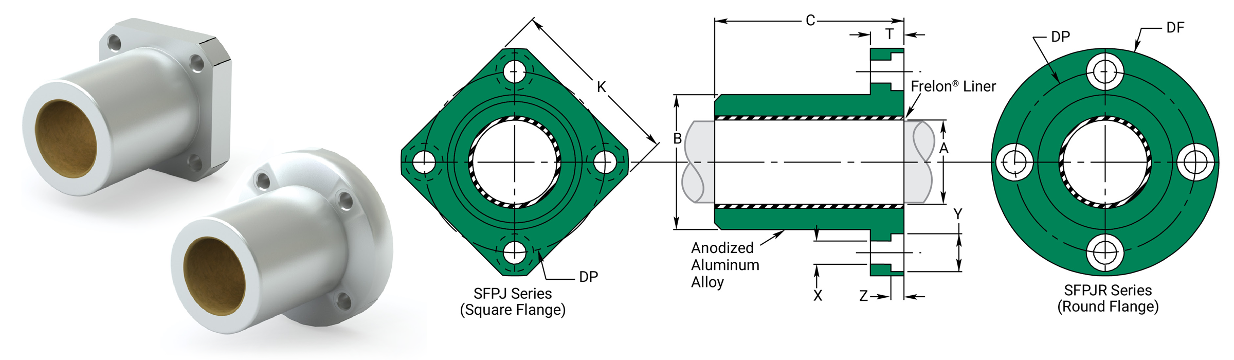
Dimensional Information
| Precision I.D. Series Similar to Preloaded Ball Bearing |
Compensated I.D. Series Similar to Standard Ball Bearing |
B Body O.D. H7 |
C Length H13 |
Effective Surface Area CM2 |
MAX Static Load N Frelon® |
||||||||||
|---|---|---|---|---|---|---|---|---|---|---|---|---|---|---|---|
| Part No. | Nominal Size mm |
A Bearing I.D. F8 |
Part No. | A Bearing I.D. |
|||||||||||
| Square | Round | MIN | MAX | Square | Round | MIN | MAX | MIN | MAX | MIN | MAX | GOLD | J & W | ||
| SFPJ06 | SFPJR06 | 6 | 6.010 | 6.028 | SFPJ06C | SFPJR06C | 6.060 | 6.078 | 11.982 | 12 | 18.8 | 19 | 1.194 | 2462 | 1236 |
| SFPJ08 | SFPJR08 | 8 | 8.013 | 8.035 | SFPJ08C | SFPJR08C | 8.063 | 8.085 | 14.982 | 15 | 23.8 | 24 | 2.011 | 4140 | 2080 |
| SFPJ10 | SFPJR10 | 10 | 10.013 | 10.035 | SFPJ10C | SFPJR10C | 10.063 | 10.085 | 18.979 | 19 | 28.8 | 29 | 3.037 | 6259 | 3139 |
| SFPJ12 | SFPJR12 | 12 | 12.016 | 12.043 | SFPJ12C | SFPJR12C | 12.066 | 12.093 | 20.979 | 21 | 29.8 | 30 | 3.770 | 7770 | 3904 |
| SFPJ13 | SFPJR13 | 13 | 13.016 | 13.043 | SFPJ13C | SFPJR13C | 13.066 | 13.093 | 22.979 | 23 | 31.8 | 32 | 4.356 | 8976 | 4503 |
| SFPJ16 | SFPJR16 | 16 | 16.016 | 16.043 | SFPJ16C | SFPJR16C | 16.066 | 16.093 | 27.979 | 28 | 36.8 | 37 | 6.199 | 12773 | 6416 |
| SFPJ20 | SFPJR20 | 20 | 20.020 | 20.053 | SFPJ20C | SFPJR20C | 20.096 | 20.129 | 31.975 | 32 | 41.8 | 42 | 8.796 | 18119 | 9104 |
| SFPJ25 | SFPJR25 | 25 | 25.020 | 25.053 | SFPJ25C | SFPJR25C | 25.096 | 25.129 | 39.975 | 40 | 58.7 | 59 | 15.446 | 31824 | 15980 |
| SFPJ30 | SFPJR30 | 30 | 30.020 | 30.053 | SFPJ30C | SFPJR30C | 30.096 | 30.129 | 44.975 | 45 | 63.7 | 64 | 20.106 | 41418 | 20797 |
| SFPJ35 | SFPJR35 | 35 | 35.020 | 35.053 | SFPJ35C | SFPJR35C | 35.096 | 35.129 | 51.970 | 52 | 69.7 | 70 | 25.656 | 52856 | 26536 |
| SFPJ40 | SFPJR40 | 40 | 40.025 | 40.064 | SFPJ40C | SFPJR40C | 40.127 | 40.166 | 59.970 | 60 | 79.7 | 80 | 33.510 | 69033 | 34669 |
| SFPJ50 | SFPJR50 | 50 | 50.025 | 50.064 | SFPJ50C | SFPJR50C | 50.127 | 50.166 | 79.965 | 80 | 99.7 | 100 | 52.360 | 107871 | 54161 |
| SFPJ60 | SFPJR60 | 60 | 60.030 | 60.076 | SFPJ60C | SFPJR60C | 60.182 | 60.228 | 89.965 | 90 | 109.6 | 110 | 69.115 | 142382 | 71495 |
| SFPJ80 | SFPJR80 | 80 | 80.030 | 80.076 | SFPJ80C | SFPJR80C | 80.182 | 80.228 | 119.965 | 120 | 139.6 | 140 | 117.286 | 241620 | 121330 |
Notes:
(1) Formula used for effective surface area is (pi * ID * L)/3.
(2) MAX static load is effective surface area times MAX load for FrelonGOLD®.
(3) - 210 kgf/cm2 is the rating for FrelonGOLD®; 105.45 kgf/cm2 is the rating for Frelon J
Mounting Dimensions
| Part No. | K Square Max. |
DF O.D. Max. |
T Length Max. |
DP Bolt Circle |
X Hole |
Y C'Bore Dia. |
Z C'Bore Depth |
Clamping Bolt | Concentricity | Squareness | SFPJ Weight kg |
SFPJR Weight kg |
|
|---|---|---|---|---|---|---|---|---|---|---|---|---|---|
| Square | Round | ||||||||||||
| SFPJ06 | SFPJR06 | 22 | 28 | 8 | 20 | 3.5 | 6 | 3.1 | M 3 | 0.012 | 0.012 | 0.011 | 0.014 |
| SFPJ08 | SFPJR08 | 25 | 32 | 8 | 24 | 3.5 | 6 | 3.1 | M 3 | 0.012 | 0.012 | 0.017 | 0.021 |
| SFPJ10 | SFPJR10 | 30 | 40 | 9 | 29 | 4.5 | 7.5 | 4.1 | M 4 | 0.012 | 0.012 | 0.029 | 0.038 |
| SFPJ12 | SFPJR12 | 32 | 42 | 9 | 32 | 4.5 | 7.5 | 4.1 | M 4 | 0.012 | 0.012 | 0.033 | 0.042 |
| SFPJ13 | SFPJR13 | 34 | 43 | 9 | 33 | 4.5 | 7.5 | 4.1 | M 4 | 0.012 | 0.012 | 0.041 | 0.048 |
| SFPJ16 | SFPJR16 | 37 | 48 | 9 | 38 | 4.5 | 7.5 | 4.1 | M 4 | 0.012 | 0.012 | 0.058 | 0.069 |
| SFPJ20 | SFPJR20 | 42 | 54 | 11 | 43 | 5.5 | 9 | 5.1 | M 5 | 0.015 | 0.015 | 0.081 | 0.097 |
| SFPJ25 | SFPJR25 | 50 | 62 | 11 | 51 | 5.5 | 9 | 5.1 | M 5 | 0.015 | 0.015 | 0.158 | 0.174 |
| SFPJ30 | SFPJR30 | 58 | 74 | 14 | 60 | 6.6 | 11 | 6.1 | M 6 | 0.015 | 0.015 | 0.216 | 0.252 |
| SFPJ35 | SFPJR35 | 64 | 82 | 14 | 67 | 6.6 | 11 | 6.1 | M 6 | 0.017 | 0.017 | 0.292 | 0.338 |
| SFPJ40 | SFPJR40 | 75 | 96 | 18 | 78 | 9.0 | 14 | 8.1 | M 8 | 0.017 | 0.017 | 0.467 | 0.547 |
| SFPJ50 | SFPJR50 | 92 | 116 | 18 | 98 | 9.0 | 14 | 8.1 | M 8 | 0.017 | 0.017 | 0.999 | 1.104 |
| SFPJ60 | SFPJR60 | 106 | 134 | 24 | 112 | 11.0 | 17 | 11.1 | M 10 | 0.020 | 0.020 | 1.359 | 1.550 |
| SFPJ80 | SFPJR80 | 136 | 164 | 24 | 142 | 11.0 | 17 | 11.1 | M 10 | 0.020 | 0.020 | 2.873 | 3.048 |
Double Flange Bearings DFPJ
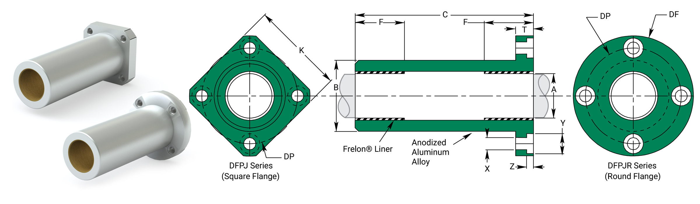
Dimensional Information
| Precision I.D. Series Similar to Preloaded Ball Bearing |
Compensated I.D. Series Similar to Standard Ball Bearing |
B Body O.D. H7 |
C Length |
F Length Each End |
Effective Surface Area CM2 |
MAX Static Load N Frelon® |
||||||||||
|---|---|---|---|---|---|---|---|---|---|---|---|---|---|---|---|---|
| Part No. | Nominal Size mm |
A Bearing I.D. F8 |
Part No. | A Bearing I.D. |
||||||||||||
| Square | Round | MIN | MAX | Square | Round | MIN | MAX | MIN | MAX | MIN | MAX | GOLD | J & W | |||
| DFPJ06 | DFPJR06 | 6 | 6.010 | 6.028 | DFPJ06C | DFPJR06C | 6.060 | 6.078 | 11.982 | 12 | 34.7 | 35 | 12 | 1.508 | 3110 | 1560 |
| DFPJ08 | DFPJR08 | 8 | 8.013 | 8.035 | DFPJ08C | DFPJR08C | 8.063 | 8.085 | 14.982 | 15 | 44.7 | 45 | 12 | 2.011 | 4140 | 2080 |
| DFPJ10 | DFPJR10 | 10 | 10.013 | 10.035 | DFPJ10C | DFPJR10C | 10.063 | 10.085 | 18.979 | 19 | 54.7 | 55 | 14 | 2.932 | 6043 | 3031 |
| DFPJ12 | DFPJR12 | 12 | 12.016 | 12.043 | DFPJ12C | DFPJR12C | 12.066 | 12.093 | 20.979 | 21 | 56.7 | 57 | 15 | 3.770 | 7770 | 3904 |
| DFPJ13 | DFPJR13 | 13 | 13.016 | 13.043 | DFPJ13C | DFPJR13C | 13.066 | 13.093 | 22.979 | 23 | 60.7 | 61 | 16 | 4.356 | 8976 | 4503 |
| DFPJ16 | DFPJR16 | 16 | 16.016 | 16.043 | DFPJ16C | DFPJR16C | 16.066 | 16.093 | 27.979 | 28 | 69.7 | 70 | 20 | 6.702 | 13803 | 6936 |
| DFPJ20 | DFPJR20 | 20 | 20.020 | 20.053 | DFPJ20C | DFPJR20C | 20.096 | 20.129 | 31.975 | 32 | 79.7 | 80 | 22 | 9.215 | 18982 | 9535 |
| DFPJ25 | DFPJR25 | 25 | 25.020 | 25.053 | DFPJ25C | DFPJR25C | 25.096 | 25.129 | 39.975 | 40 | 111.6 | 112 | 33 | 17.279 | 35600 | 17874 |
| DFPJ30 | DFPJR30 | 30 | 30.020 | 30.053 | DFPJ30C | DFPJR30C | 30.096 | 30.129 | 44.975 | 45 | 122.6 | 123 | 35 | 21.991 | 45303 | 22749 |
| DFPJ35 | DFPJR35 | 35 | 35.020 | 35.053 | DFPJ35C | DFPJR35C | 35.096 | 35.129 | 51.970 | 52 | 134.6 | 135 | 40 | 29.322 | 60410 | 30333 |
| DFPJ40 | DFPJR40 | 40 | 40.025 | 40.064 | DFPJ40C | DFPJR40C | 40.127 | 40.166 | 59.970 | 60 | 150.6 | 151 | 44 | 36.861 | 75939 | 38131 |
| DFPJ50 | DFPJR50 | 50 | 50.025 | 50.064 | DFPJ50C | DFPJR50C | 50.127 | 50.166 | 79.965 | 80 | 191.6 | 192 | 70 | 73.304 | 151015 | 75831 |
| DFPJ60 | DFPJR60 | 60 | 60.030 | 60.076 | DFPJ60C | DFPJR60C | 60.182 | 60.228 | 89.965 | 90 | 208.6 | 209 | 73 | 91.735 | 188980 | 94892 |
Notes:
(1) Formula used for effective surface area is (pi * ID * L)/3.
(2) MAX static load is effective surface area times MAX load for FrelonGOLD®.
(3) - 210 kgf/cm2 is the rating for FrelonGOLD®; 105.45 kgf/cm2 is the rating for Frelon J.
(4) Frelon pads in each end (F dimension).
Mounting Dimensions
| Part No. | K Square Max. |
DF O.D. Max. |
T Length Max. |
DP Bolt Circle |
X Hole |
Y C'Bore Dia. |
Z C'Bore Depth |
Clamping Bolt | Concentricity | Squareness | DFPJ Weight kg |
DFPJR Weight kg |
|
|---|---|---|---|---|---|---|---|---|---|---|---|---|---|
| Square | Round | ||||||||||||
| DFPJ06 | DFPJR06 | 22 | 28 | 8 | 20 | 3.5 | 6 | 3.1 | M 3 | 0.015 | 0.015 | 0.015 | 0.018 |
| DFPJ08 | DFPJR08 | 25 | 32 | 8 | 24 | 3.5 | 6 | 3.1 | M 3 | 0.015 | 0.015 | 0.024 | 0.028 |
| DFPJ10 | DFPJR10 | 30 | 40 | 9 | 29 | 4.5 | 7.5 | 4.1 | M 4 | 0.015 | 0.015 | 0.044 | 0.053 |
| DFPJ12 | DFPJR12 | 32 | 42 | 9 | 32 | 4.5 | 7.5 | 4.1 | M 4 | 0.015 | 0.015 | 0.051 | 0.060 |
| DFPJ13 | DFPJR13 | 34 | 43 | 9 | 33 | 4.5 | 7.5 | 4.1 | M 4 | 0.015 | 0.015 | 0.063 | 0.071 |
| DFPJ16 | DFPJR16 | 37 | 48 | 9 | 38 | 4.5 | 7.5 | 4.1 | M 4 | 0.015 | 0.015 | 0.096 | 0.107 |
| DFPJ20 | DFPJR20 | 42 | 54 | 11 | 43 | 5.5 | 9 | 5.1 | M 5 | 0.017 | 0.017 | 0.133 | 0.149 |
| DFPJ25 | DFPJR25 | 50 | 62 | 11 | 51 | 5.5 | 9 | 5.1 | M 5 | 0.017 | 0.017 | 0.270 | 0.286 |
| DFPJ30 | DFPJR30 | 58 | 74 | 14 | 60 | 6.6 | 11 | 6.1 | M 6 | 0.017 | 0.017 | 0.360 | 0.397 |
| DFPJ35 | DFPJR35 | 64 | 82 | 14 | 67 | 6.6 | 11 | 6.1 | M 6 | 0.020 | 0.020 | 0.501 | 0.547 |
| DFPJ40 | DFPJR40 | 75 | 96 | 18 | 78 | 9.0 | 14 | 8.1 | M 8 | 0.020 | 0.020 | 0.776 | 0.856 |
| DFPJ50 | DFPJR50 | 92 | 116 | 18 | 98 | 9.0 | 14 | 8.1 | M 8 | 0.020 | 0.020 | 1.780 | 1.885 |
| DFPJ60 | DFPJR60 | 106 | 134 | 24 | 112 | 11.0 | 17 | 11.1 | M 10 | 0.025 | 0.025 | 2.329 | 2.519 |
Center Flange Bearings CFPJ
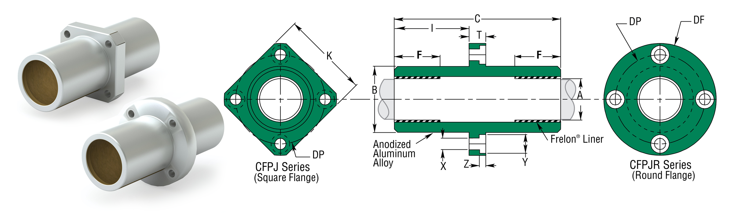
Dimensional Information
| Precision I.D. Series Similar to Preloaded Ball Bearing |
Compensated I.D. Series Similar to Standard Ball Bearing |
B Body O.D. H7 |
C Length |
I Length To FLNG. |
F Length Each End |
Effective Surface Area CM2 |
MAX Static Load N Frelon® |
||||||||||
|---|---|---|---|---|---|---|---|---|---|---|---|---|---|---|---|---|---|
| Part No. | Nominal Size mm |
A Bearing I.D. F8 |
Part No. | A Bearing I.D. |
|||||||||||||
| Square | Round | MIN | MAX | Square | Round | MIN | MAX | MIN | MAX | MIN | MAX | GOLD | J & W | ||||
| CFPJ06 | CFPJR06 | 6 | 6.010 | 6.028 | CFPJ06C | CFPJR06C | 6.060 | 6.078 | 11.982 | 12 | 34.7 | 35.3 | 13.5 | 12 | 1.508 | 3110 | 1560 |
| CFPJ08 | CFPJR08 | 8 | 8.013 | 8.035 | CFPJ08C | CFPJR08C | 8.063 | 8.085 | 14.982 | 15 | 44.7 | 45.3 | 18.5 | 12 | 2.011 | 4140 | 2080 |
| CFPJ10 | CFPJR10 | 10 | 10.013 | 10.035 | CFPJ10C | CFPJR10C | 10.063 | 10.085 | 18.979 | 19 | 54.7 | 55.3 | 23.0 | 14 | 2.932 | 6043 | 3031 |
| CFPJ12 | CFPJR12 | 12 | 12.016 | 12.043 | CFPJ12C | CFPJR12C | 12.066 | 12.093 | 20.979 | 21 | 56.7 | 57.3 | 24.0 | 15 | 3.770 | 7770 | 3904 |
| CFPJ13 | CFPJR13 | 13 | 13.016 | 13.043 | CFPJ13C | CFPJR13C | 13.066 | 13.093 | 22.979 | 23 | 60.7 | 61.3 | 26.0 | 16 | 4.356 | 8976 | 4503 |
| CFPJ16 | CFPJR16 | 16 | 16.016 | 16.043 | CFPJ16C | CFPJR16C | 16.066 | 16.093 | 27.979 | 28 | 69.7 | 70.3 | 30.5 | 20 | 6.702 | 13803 | 6936 |
| CFPJ20 | CFPJR20 | 20 | 20.020 | 20.053 | CFPJ20C | CFPJR20C | 20.096 | 20.129 | 31.975 | 32 | 79.7 | 80.3 | 34.5 | 22 | 9.215 | 18982 | 9535 |
| CFPJ25 | CFPJR25 | 25 | 25.020 | 25.053 | CFPJ25C | CFPJR25C | 25.096 | 25.129 | 39.975 | 40 | 111.7 | 112.3 | 50.5 | 33 | 17.279 | 35600 | 17874 |
| CFPJ30 | CFPJR30 | 30 | 30.020 | 30.053 | CFPJ30C | CFPJR30C | 30.096 | 30.129 | 44.975 | 45 | 122.7 | 123.3 | 54.5 | 35 | 21.991 | 45303 | 22749 |
| CFPJ35 | CFPJR35 | 35 | 35.020 | 35.053 | CFPJ35C | CFPJR35C | 35.096 | 35.129 | 51.970 | 52 | 134.7 | 135.3 | 60.5 | 40 | 29.322 | 60410 | 30333 |
| CFPJ40 | CFPJR40 | 40 | 40.025 | 40.064 | CFPJ40C | CFPJR40C | 40.127 | 40.166 | 59.970 | 60 | 150.7 | 151.3 | 66.5 | 44 | 36.861 | 75939 | 38131 |
| CFPJ50 | CFPJR50 | 50 | 50.025 | 50.064 | CFPJ50C | CFPJR50C | 50.127 | 50.166 | 79.965 | 80 | 191.7 | 192.3 | 87.0 | 70 | 73.304 | 151015 | 75831 |
| CFPJ60 | CFPJR60 | 60 | 60.030 | 60.076 | CFPJ60C | CFPJR60C | 60.182 | 60.228 | 89.965 | 90 | 208.7 | 209.3 | 92.5 | 73 | 91.735 | 188980 | 94892 |
Notes:
(1) Formula used for effective surface area is (pi * ID * L)/3.
(2) MAX static load is effective surface area times MAX load for FrelonGOLD®.
(3) - 210 kgf/cm2 is the rating for FrelonGOLD®; 105.45 kgf/cm2 is the rating for Frelon J.
(4) Frelon pads in each end (F dimension).
Mounting Dimensions
| Part No. | K Square Max. |
DF O.D. Max. |
T Length Max. |
DP Bolt Circle |
X Hole |
Y C'Bore Dia. |
Z C'Bore Depth |
Clamping Bolt | Concentricity | Squareness | CFPJ Weight kg |
CFPJR Weight kg |
|
|---|---|---|---|---|---|---|---|---|---|---|---|---|---|
| Square | Round | ||||||||||||
| CFPJ06 | CFPJR06 | 22 | 28 | 8 | 20 | 3.5 | 6 | 3.1 | M3 | 0.015 | 0.015 | 0.015 | 0.018 |
| CFPJ08 | CFPJR08 | 25 | 32 | 8 | 24 | 3.5 | 6 | 3.1 | M3 | 0.015 | 0.015 | 0.024 | 0.028 |
| CFPJ10 | CFPJR10 | 30 | 40 | 9 | 29 | 4.5 | 7.5 | 4.1 | M4 | 0.015 | 0.015 | 0.044 | 0.053 |
| CFPJ12 | CFPJR12 | 32 | 42 | 9 | 32 | 4.5 | 7.5 | 4.1 | M4 | 0.015 | 0.015 | 0.051 | 0.060 |
| CFPJ13 | CFPJR13 | 34 | 43 | 9 | 33 | 4.5 | 7.5 | 4.1 | M4 | 0.015 | 0.015 | 0.063 | 0.071 |
| CFPJ16 | CFPJR16 | 37 | 48 | 9 | 38 | 4.5 | 7.5 | 4.1 | M4 | 0.015 | 0.015 | 0.096 | 0.107 |
| CFPJ20 | CFPJR20 | 42 | 54 | 11 | 43 | 5.5 | 9 | 5.1 | M5 | 0.017 | 0.017 | 0.133 | 0.149 |
| CFPJ25 | CFPJR25 | 50 | 62 | 11 | 51 | 5.5 | 9 | 5.1 | M5 | 0.017 | 0.017 | 0.270 | 0.286 |
| CFPJ30 | CFPJR30 | 58 | 74 | 14 | 60 | 6.6 | 11 | 6.1 | M6 | 0.017 | 0.017 | 0.360 | 0.397 |
| CFPJ35 | CFPJR35 | 64 | 82 | 14 | 67 | 6.6 | 11 | 6.1 | M6 | 0.020 | 0.020 | 0.501 | 0.547 |
| CFPJ40 | CFPJR40 | 75 | 96 | 18 | 78 | 9.0 | 14 | 8.1 | M8 | 0.020 | 0.020 | 0.776 | 0.856 |
| CFPJ50 | CFPJR50 | 92 | 116 | 18 | 98 | 9.0 | 14 | 8.1 | M8 | 0.020 | 0.020 | 1.780 | 1.885 |
| CFPJ60 | CFPJR60 | 106 | 134 | 24 | 112 | 11.0 | 17 | 11.1 | M10 | 0.025 | 0.025 | 2.329 | 2.519 |
⚠ Only certified Simplicity 60 Plus Shafting provides maximum bearing performance.
Linear JIS Metric Ball Bearings Precision
Ball Bearings JP
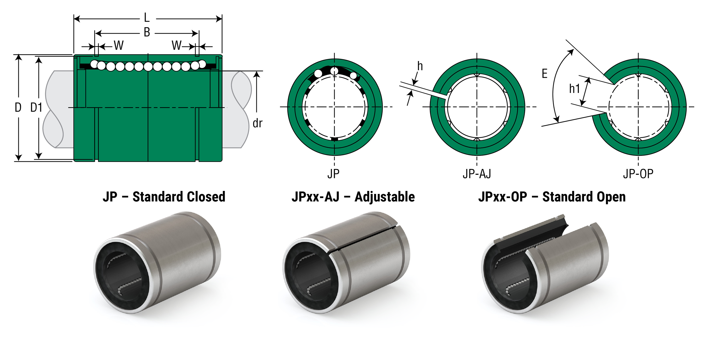
Dimensional Information
| Part No. | Nominal Diameter | Ball Circuit |
Weight G |
Major Dimensions & Tolerances | |||||||||
|---|---|---|---|---|---|---|---|---|---|---|---|---|---|
| Standard Closed |
Adjustable | Standard Open |
Size mm |
dr mm |
Tolerance mm |
D mm |
Tolerance mm |
L mm |
Tolerance mm |
B mm |
Tolerance mm |
||
| JP8G | - | - | 8 | 8 | 0/-0.009 | 4 | 16 | 15 | 0/-0.011 | 24 | 0/-0.2 | 17.5 | 0/-0.2 |
| JP10G | - | - | 10 | 10 | 0/-0.009 | 4 | 30 | 19 | 0/-0.013 | 29 | 0/-0.2 | 22 | 0/-0.2 |
| JP12G | JP12G-AJ | JP12G-OP | 12 | 12 | 0/-0.009 | 4 | 31.5 | 21 | 0/-0.013 | 30 | 0/-0.2 | 23 | 0/-0.2 |
| JP13G | JP13G-AJ | JP13G-OP | 13 | 13 | 0/-0.009 | 4 | 43 | 23 | 0/-0.013 | 32 | 0/-0.2 | 23 | 0/-0.2 |
| JP16G | JP16G-AJ | JP16G-OP | 16 | 16 | 0/-0.009 | 5 | 69 | 28 | 0/-0.013 | 37 | 0/-0.2 | 26.5 | 0/-0.2 |
| JP20G | JP20G-AJ | JP20G-OP | 20 | 20 | 0/-0.010 | 5 | 87 | 32 | 0/-0.016 | 42 | 0/-0.2 | 30.5 | 0/-0.2 |
| JP25G | JP25G-AJ | JP25G-OP | 25 | 25 | 0/-0.010 | 6 | 220 | 40 | 0/-0.016 | 59 | 0/-0.3 | 41 | 0/-0.3 |
| JP30G | JP30G-AJ | JP30G-OP | 30 | 30 | 0/-0.010 | 6 | 250 | 45 | 0/-0.016 | 64 | 0/-0.3 | 44.5 | 0/-0.3 |
| JP35G | JP35G-AJ | JP35G-OP | 35 | 35 | 0/-0.012 | 6 | 390 | 52 | 0/-0.019 | 70 | 0/-0.3 | 49.5 | 0/-0.3 |
| JP40G | JP40G-AJ | JP40G-OP | 40 | 40 | +0/-0.012 | 6 | 585 | 60 | 0/-0.019 | 80 | 0/-0.3 | 60.5 | 0/-0.3 |
| JP50G | JP50G-AJ | JP50G-OP | 50 | 50 | +0/-0.015 | 6 | 1580 | 80 | 0/-0.022 | 100 | 0/-0.3 | 74 | 0/-0.3 |
| Part No. | Nominal Diameter | Major Dimensions & Tolerances | Load Ratings | |||||||||||
|---|---|---|---|---|---|---|---|---|---|---|---|---|---|---|
| Standard Closed |
Adjustable | Standard Open |
Size mm |
dr mm |
Tolerance mm |
W mm |
D1 mm |
H mm |
H1 mm |
E Slot Angle |
MAX Eccentricity µm |
MAX Radial Clearance µm |
Dynamic C N |
Static Co N |
| JP8G | - | - | 8 | 8 | 0/-0.009 | 1.1 | 14.3 | 1 | - | - | 12 | -5 | 260 | 400 |
| JP10G | - | - | 10 | 10 | 0/-0.009 | 1.3 | 18 | 1 | - | - | 12 | -5 | 370 | 540 |
| JP12G | JP12G-AJ | JP12G-OP | 12 | 12 | 0/-0.009 | 1.3 | 20 | 1.5 | 8 | 80° | 12 | -5 | 410 | 590 |
| JP13G | JP13G-AJ | JP13G-OP | 13 | 13 | 0/-0.009 | 1.3 | 22 | 1.5 | 9 | 80° | 12 | -5 | 500 | 770 |
| JP16G | JP16G-AJ | JP16G-OP | 16 | 16 | 0/-0.009 | 1.6 | 27 | 1.5 | 11 | 80° | 12 | -7 | 770 | 1170 |
| JP20G | JP20G-AJ | JP20G-OP | 20 | 20 | 0/-0.010 | 1.6 | 30.5 | 1.5 | 11 | 60° | 15 | -7 | 860 | 1370 |
| JP25G | JP25G-AJ | JP25G-OP | 25 | 25 | 0/-0.010 | 1.85 | 38 | 2 | 12 | 50° | 15 | -9 | 980 | 1560 |
| JP30G | JP30G-AJ | JP30G-OP | 30 | 30 | 0/-0.010 | 1.85 | 43 | 2.5 | 15 | 50° | 15 | -9 | 1560 | 2740 |
| JP35G | JP35G-AJ | JP35G-OP | 35 | 35 | 0/-0.012 | 2.1 | 49 | 2.5 | 17 | 50° | 20 | -9 | 1660 | 3130 |
| JP40G | JP40G-AJ | JP40G-OP | 40 | 40 | +0/-0.012 | 2.1 | 57 | 3 | 20 | 50° | 20 | -13 | 2150 | 4010 |
| JP50G | JP50G-AJ | JP50G-OP | 50 | 50 | +0/-0.015 | 2.6 | 76.5 | 3 | 25 | 50° | 20 | -13 | 3820 | 7930 |
Linear JIS Metric Ball Bearings
Double Wide
Double Wide Ball Bearings JP-W
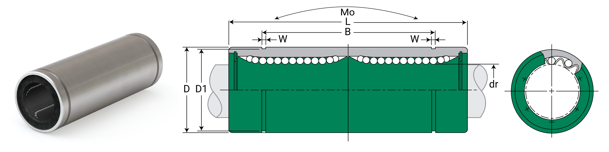
Dimensional Information
| Part No. Standard Polymer Cage |
Nominal Shaft Diameter | Ball Circuit | Weight G |
Major Dimensions & Tolerances | |||||||
|---|---|---|---|---|---|---|---|---|---|---|---|
| Size mm |
dr mm |
Tolerance mm |
D mm |
Tolerance mm |
L mm |
Tolerance mm |
B mm |
Tolerance mm |
|||
| JP8GW | 8 | 8 | 0/-0.010 | 4 | 31 | 15 | 0/-0.013 | 45 | 0/-0.3 | 35 | 0/-0.3 |
| JP12GW | 12 | 12 | 0/-0.010 | 4 | 80 | 21 | 0/-0.016 | 57 | 0/-0.3 | 46 | 0/-0.3 |
| JP16GW | 16 | 16 | 0/-0.010 | 5 | 145 | 28 | 0/-0.016 | 70 | 0/-0.3 | 53 | 0/-0.3 |
| JP20GW | 20 | 20 | 0/-0.012 | 5 | 180 | 32 | 0/-0.019 | 80 | 0/-0.3 | 61 | 0/-0.3 |
| JP25GW | 25 | 25 | 0/-0.012 | 6 | 440 | 40 | 0/-0.019 | 112 | 0/-0.4 | 82 | 0/-0.4 |
| JP30GW | 30 | 30 | 0/-0.012 | 6 | 580 | 45 | 0/-0.019 | 123 | 0/-0.4 | 89 | 0/-0.4 |
| JP40GW | 40 | 40 | 0/-0.015 | 6 | 1170 | 60 | 0/-0.022 | 151 | 0/-0.4 | 121 | 0/-0.4 |
| JP50GW | 50 | 50 | 0/-0.015 | 6 | 3100 | 80 | 0/-0.022 | 192 | 0/-0.4 | 148 | 0/-0.4 |
| Part No. Standard Polymer Cage |
Nominal Shaft Diameter | Major Dimensions & Tolerances | Loading Ratings | |||||
|---|---|---|---|---|---|---|---|---|
| Size mm |
dr mm |
Tolerance mm |
W mm |
D1 mm |
MAX Eccentricity µm |
Dynamic C N |
Static Co N |
|
| JP8GW | 8 | 8 | 0/-0.010 | 1.1 | 14.3 | 15 | 431 | 784 |
| JP12GW | 12 | 12 | 0/-0.010 | 1.3 | 20 | 15 | 657 | 1200 |
| JP16GW | 16 | 16 | 0/-0.010 | 1.6 | 27 | 15 | 1230 | 2350 |
| JP20GW | 20 | 20 | 0/-0.012 | 1.6 | 30.5 | 20 | 1400 | 2750 |
| JP25GW | 25 | 25 | 0/-0.012 | 1.85 | 38 | 20 | 1560 | 3140 |
| JP30GW | 30 | 30 | 0/-0.012 | 1.85 | 43 | 20 | 2490 | 5490 |
| JP40GW | 40 | 40 | 0/-0.015 | 2.1 | 57 | 25 | 3430 | 8040 |
| JP50GW | 50 | 50 | 0/-0.015 | 2.6 | 76.5 | 25 | 6080 | 15900 |
⚠ Only certified Simplicity 60 Plus Shafting provides maximum bearing performance.
Linear JIS Metric Ball Bearings
Square Flange Mount
Ball Bearings – Square Flange Mount JPK
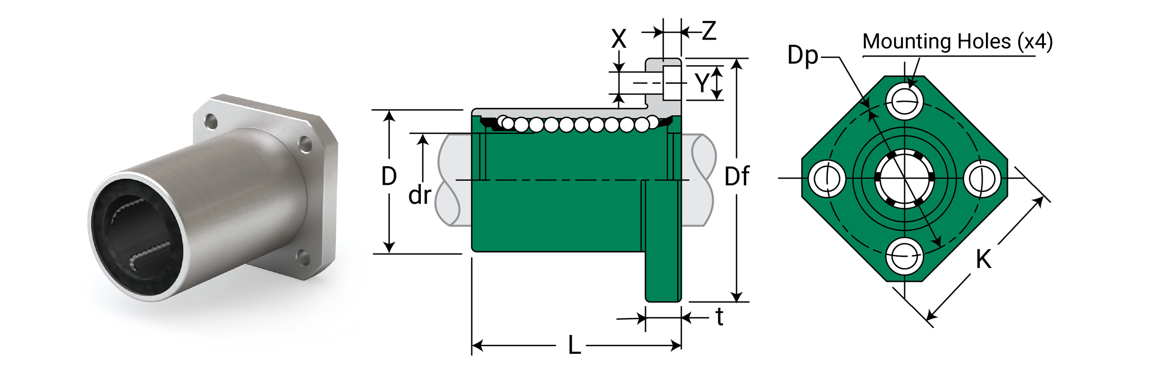
Dimensional Information
| Part No. Standard Polymer Cage |
Nominal Shaft Diameter | Ball Circuit | Weight G |
Major Dimensions & Tolerances | |||||
|---|---|---|---|---|---|---|---|---|---|
| Size mm |
dr mm |
Tolerance mm |
D mm |
Tolerance mm |
L mm |
Tolerance mm |
|||
| JPK8G | 8 | 8 | 0/-0.009 | 4 | 37 | 15 | 0/-0.013 | 24 | ±0.3 |
| JPK12G | 12 | 12 | 0/-0.009 | 4 | 76 | 21 | 0/-0.016 | 30 | ±0.3 |
| JPK16G | 16 | 16 | 0/-0.009 | 5 | 120 | 28 | 0/-0.016 | 37 | ±0.3 |
| JPK20G | 20 | 20 | 0/-0.010 | 5 | 180 | 32 | 0/-0.019 | 42 | ±0.3 |
| JPK25G | 25 | 25 | 0/-0.010 | 6 | 340 | 40 | 0/-0.019 | 59 | ±0.3 |
| JPK30G | 30 | 30 | 0/-0.010 | 6 | 470 | 45 | 0/-0.019 | 64 | ±0.3 |
| JPK40G | 40 | 40 | 0/-0.012 | 6 | 1060 | 60 | 0/-0.022 | 80 | ±0.3 |
| JPK50G | 50 | 50 | 0/-0.012 | 6 | 2200 | 80 | 0/-0.022 | 100 | ±0.3 |
| Part No. Standard Polymer Cage |
Nominal Shaft Diameter | Major Dimensions & Tolerances - Flange | Loading Ratings | |||||||||||
|---|---|---|---|---|---|---|---|---|---|---|---|---|---|---|
| Size mm |
dr mm |
Tolerance mm |
Df mm |
K mm |
T mm |
Dp mm |
X mm |
Y mm |
Z mm |
Eccentricity µm |
Squareness µm |
Dynamic C N |
Static Co N |
|
| JPK8G | 8 | 8 | 0/-0.009 | 32 | 25 | 5 | 24 | 3.5 | 6.5 | 3.1 | 12 | 12 | 274 | 392 |
| JPK12G | 12 | 12 | 0/-0.009 | 42 | 32 | 6 | 32 | 4.5 | 8 | 4.1 | 12 | 12 | 510 | 784 |
| JPK16G | 16 | 16 | 0/-0.009 | 48 | 37 | 6 | 38 | 4.5 | 8 | 4.1 | 12 | 12 | 774 | 1180 |
| JPK20G | 20 | 20 | 0/-0.010 | 54 | 42 | 8 | 43 | 5.5 | 9.3 | 5.1 | 15 | 15 | 882 | 1370 |
| JPK25G | 25 | 25 | 0/-0.010 | 62 | 50 | 8 | 51 | 5.5 | 9.3 | 5.1 | 15 | 15 | 980 | 1570 |
| JPK30G | 30 | 30 | 0/-0.010 | 74 | 58 | 10 | 60 | 6.6 | 11 | 6.1 | 15 | 15 | 1570 | 2740 |
| JPK40G | 40 | 40 | 0/-0.012 | 96 | 75 | 13 | 78 | 9 | 14 | 8.1 | 20 | 20 | 2160 | 4020 |
| JPK50G | 50 | 50 | 0/-0.012 | 116 | 92 | 13 | 98 | 9 | 14 | 8.1 | 20 | 20 | 3820 | 7940 |
⚠ Only certified Simplicity 60 Plus Shafting provides maximum bearing performance.
Linear JIS Metric Ball Bearings
Round Flange Mount
Ball Bearings – Round Flange Mount JPF
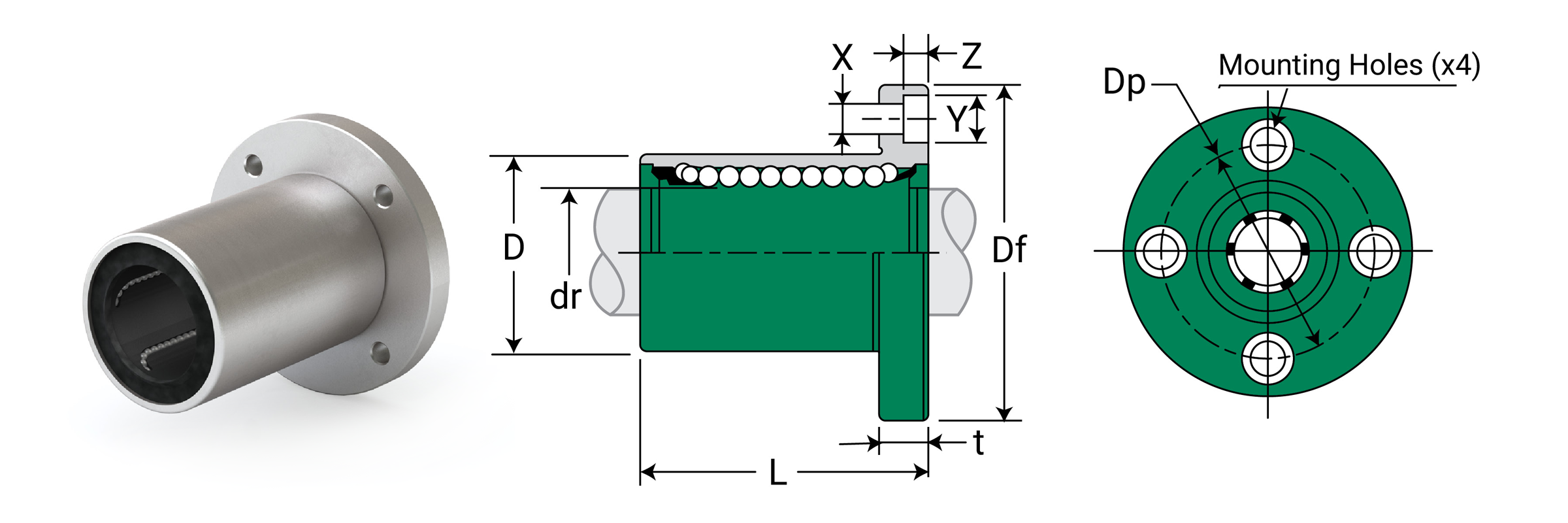
Dimensional Information
| Part No. Standard Polymer Cage |
Nominal Shaft Diameter | Ball Circuit | Weight G |
Major Dimensions & Tolerances | |||||
|---|---|---|---|---|---|---|---|---|---|
| Size mm |
dr mm |
Tolerance mm |
D mm |
Tolerance mm |
L mm |
Tolerance mm |
|||
| JPF8G | 8 | 8 | 0/-0.009 | 4 | 37 | 15 | 0/-0.013 | 24 | ±0.3 |
| JPF12G | 12 | 12 | 0/-0.009 | 4 | 76 | 21 | 0/-0.016 | 30 | ±0.3 |
| JPF16G | 16 | 16 | 0/-0.009 | 5 | 120 | 28 | 0/-0.016 | 37 | ±0.3 |
| JPF20G | 20 | 20 | 0/-0.010 | 5 | 180 | 32 | 0/-0.019 | 42 | ±0.3 |
| JPF25G | 25 | 25 | 0/-0.010 | 6 | 340 | 40 | 0/-0.019 | 59 | ±0.3 |
| JPF30G | 30 | 30 | 0/-0.010 | 6 | 470 | 45 | 0/-0.019 | 64 | ±0.3 |
| JPF40G | 40 | 40 | 0/-0.012 | 6 | 1060 | 60 | 0/-0.022 | 80 | ±0.3 |
| JPF50G | 50 | 50 | 0/-0.012 | 6 | 2200 | 80 | 0/-0.022 | 100 | ±0.3 |
| Part No. Standard Polymer Cage |
Nominal Shaft Diameter | Major Dimensions & Tolerances - Flange | Loading Ratings | ||||||||||
|---|---|---|---|---|---|---|---|---|---|---|---|---|---|
| Size mm |
dr mm |
Tolerance mm |
Df mm |
T mm |
Dp mm |
X mm |
Y mm |
Z mm |
Eccentricity µm |
Squareness µm |
Dynamic C N |
Static Co N |
|
| JPF8G | 8 | 8 | 0/-0.009 | 32 | 5 | 24 | 3.5 | 6.5 | 3.1 | 12 | 12 | 274 | 392 |
| JPF12G | 12 | 12 | 0/-0.009 | 42 | 6 | 32 | 4.5 | 8 | 4.1 | 12 | 12 | 510 | 784 |
| JPF16G | 16 | 16 | 0/-0.009 | 48 | 6 | 38 | 4.5 | 8 | 4.1 | 12 | 12 | 774 | 1180 |
| JPF20G | 20 | 20 | 0/-0.010 | 54 | 8 | 43 | 5.5 | 9.3 | 5.1 | 15 | 15 | 882 | 1370 |
| JPF25G | 25 | 25 | 0/-0.010 | 62 | 8 | 51 | 5.5 | 9.3 | 5.1 | 15 | 15 | 980 | 1570 |
| JPF30G | 30 | 30 | 0/-0.010 | 74 | 10 | 60 | 6.6 | 11 | 6.1 | 15 | 15 | 1570 | 2740 |
| JPF40G | 40 | 40 | 0/-0.012 | 96 | 13 | 78 | 9 | 14 | 8.1 | 20 | 20 | 2160 | 4020 |
| JPF50G | 50 | 50 | 0/-0.012 | 116 | 13 | 98 | 9 | 14 | 8.1 | 20 | 20 | 3820 | 7940 |
⚠ Only certified Simplicity 60 Plus Shafting provides maximum bearing performance.
Linear JIS Metric Ball Bearings
Double Wide Mount
Double Wide Ball Bearings – Square Flange Mount JPK-W
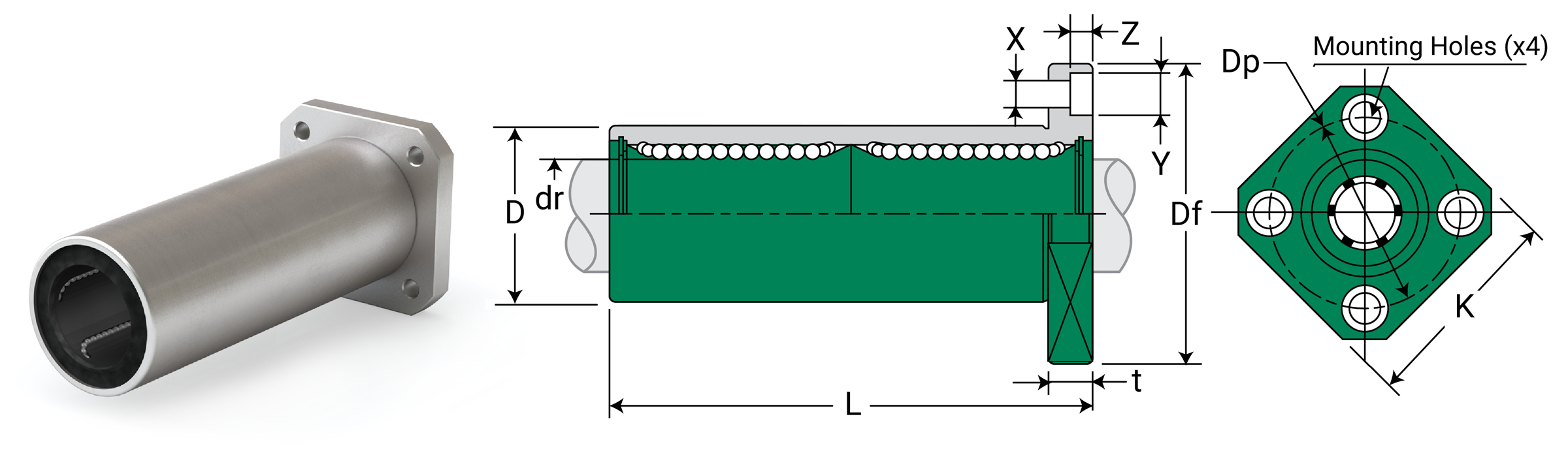
Dimensional Information
| Part No. Standard Polymer Cage |
Nominal Shaft Diameter | Ball Circuit | Weight G |
Major Dimensions & Tolerances | |||||
|---|---|---|---|---|---|---|---|---|---|
| Size mm |
dr mm |
Tolerance mm |
D mm |
Tolerance mm |
L mm |
Tolerance mm |
|||
| JPK8GW | 8 | 8 | 0/-0.010 | 4 | 43 | 15 | 0/-0.013 | 45 | ±0.3 |
| JPK12GW | 12 | 12 | 0/-0.010 | 4 | 90 | 21 | 0/-0.016 | 57 | ±0.3 |
| JPK16GW | 16 | 16 | 0/-0.010 | 5 | 165 | 28 | 0/-0.016 | 70 | ±0.3 |
| JPK20GW | 20 | 20 | 0/-0.010 | 5 | 225 | 32 | 0/-0.019 | 80 | ±0.3 |
| JPK25GW | 25 | 25 | 0/-0.012 | 6 | 500 | 40 | 0/-0.019 | 112 | ±0.3 |
| JPK30GW | 30 | 30 | 0/-0.012 | 6 | 590 | 45 | 0/-0.019 | 123 | ±0.3 |
| JPK40GW | 40 | 40 | 0/-0.015 | 6 | 1380 | 60 | 0/-0.022 | 154 | ±0.3 |
| JPK50GW | 50 | 50 | 0/-0.015 | 6 | 3400 | 80 | 0/-0.025 | 192 | ±0.3 |
| Part No. Standard Polymer Cage |
Nominal Shaft Diameter | Major Dimensions & Tolerances - Flange | Loading Ratings | |||||||||||
|---|---|---|---|---|---|---|---|---|---|---|---|---|---|---|
| Size mm |
dr mm |
Tolerance mm |
Df mm |
K mm |
T mm |
Dp mm |
X mm |
Y mm |
Z mm |
Eccentricity µm |
Squareness µm |
Dynamic C N |
Static Co N |
|
| JPK8GW | 8 | 8 | 0/-0.010 | 32 | 25 | 5 | 24 | 3.5 | 6.5 | 3.1 | 15 | 15 | 431 | 784 |
| JPK12GW | 12 | 12 | 0/-0.010 | 42 | 32 | 6 | 32 | 4.5 | 8 | 4.1 | 15 | 15 | 813 | 1570 |
| JPK16GW | 16 | 16 | 0/-0.010 | 48 | 37 | 6 | 38 | 4.5 | 8 | 4.1 | 15 | 15 | 1230 | 2350 |
| JPK20GW | 20 | 20 | 0/-0.010 | 54 | 42 | 8 | 43 | 5.5 | 9.3 | 5.1 | 20 | 20 | 1400 | 2740 |
| JPK25GW | 25 | 25 | 0/-0.012 | 62 | 50 | 8 | 51 | 5.5 | 9.3 | 5.1 | 20 | 20 | 1560 | 3140 |
| JPK30GW | 30 | 30 | 0/-0.012 | 74 | 58 | 10 | 60 | 6.6 | 11 | 6.1 | 20 | 20 | 2490 | 5490 |
| JPK40GW | 40 | 40 | 0/-0.015 | 96 | 75 | 13 | 78 | 9 | 14 | 8.1 | 25 | 25 | 3430 | 8040 |
| JPK50GW | 50 | 50 | 0/-0.015 | 116 | 92 | 13 | 98 | 9 | 14 | 8.1 | 25 | 25 | 6080 | 15900 |
Double Wide Ball Bearings – Round Flange Mount JPF-W
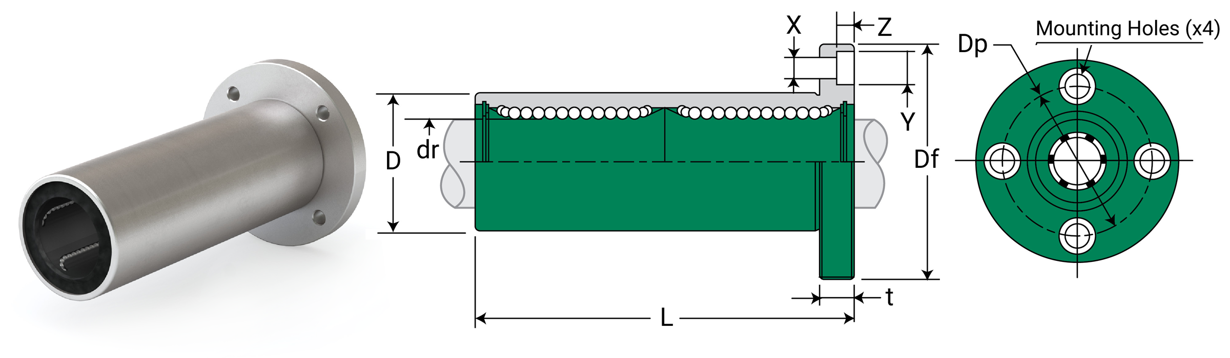
Dimensional Information
| Part No. Standard Polymer Cage |
Nominal Shaft Diameter | Ball Circuit | Weight G |
Major Dimensions & Tolerances | |||||
|---|---|---|---|---|---|---|---|---|---|
| Size mm |
dr mm |
Tolerance mm |
D mm |
Tolerance mm |
L mm |
Tolerance mm |
|||
| JPF8GW | 8 | 8 | 0/-0.010 | 4 | 51 | 15 | 0/-0.013 | 45 | ±0.3 |
| JPF12GW | 12 | 12 | 0/-0.010 | 4 | 110 | 21 | 0/-0.016 | 57 | ±0.3 |
| JPF16GW | 16 | 16 | 0/-0.010 | 5 | 190 | 28 | 0/-0.016 | 70 | ±0.3 |
| JPF20GW | 20 | 20 | 0/-0.010 | 5 | 260 | 32 | 0/-0.019 | 80 | ±0.3 |
| JPF25GW | 25 | 25 | 0/-0.012 | 6 | 540 | 40 | 0/-0.019 | 112 | ±0.3 |
| JPF30GW | 30 | 30 | 0/-0.012 | 6 | 680 | 45 | 0/-0.019 | 123 | ±0.3 |
| JPF40GW | 40 | 40 | 0/-0.015 | 6 | 1570 | 60 | 0/-0.022 | 154 | ±0.3 |
| JPF50GW | 50 | 50 | 0/-0.020 | 6 | 3600 | 80 | 0/-0.025 | 192 | ±0.3 |
| Part No. Standard Polymer Cage |
Nominal Shaft Diameter | Major Dimensions & Tolerances - Flange | Loading Ratings | ||||||||||
|---|---|---|---|---|---|---|---|---|---|---|---|---|---|
| Size mm |
dr mm |
Tolerance mm |
Df mm |
T mm |
Dp mm |
X mm |
Y mm |
Z mm |
Eccentricity µm |
Squareness µm |
Dynamic C N |
Static Co N |
|
| JPF8GW | 8 | 8 | 0/-0.010 | 32 | 5 | 24 | 3.5 | 6.5 | 3.1 | 15 | 15 | 431 | 784 |
| JPF12GW | 12 | 12 | 0/-0.010 | 42 | 6 | 32 | 4.5 | 8 | 4.1 | 15 | 15 | 813 | 1570 |
| JPF16GW | 16 | 16 | 0/-0.010 | 48 | 6 | 38 | 4.5 | 8 | 4.1 | 15 | 15 | 1230 | 2350 |
| JPF20GW | 20 | 20 | 0/-0.010 | 54 | 8 | 43 | 5.5 | 9.3 | 5.1 | 20 | 20 | 1400 | 2740 |
| JPF25GW | 25 | 25 | 0/-0.012 | 62 | 8 | 51 | 5.5 | 9.3 | 5.1 | 20 | 20 | 1560 | 3140 |
| JPF30GW | 30 | 30 | 0/-0.012 | 74 | 10 | 60 | 6.6 | 11 | 6.1 | 20 | 20 | 2490 | 5490 |
| JPF40GW | 40 | 40 | 0/-0.015 | 96 | 13 | 78 | 9 | 14 | 8.1 | 25 | 25 | 3430 | 8040 |
| JPF50GW | 50 | 50 | 0/-0.020 | 116 | 13 | 98 | 9 | 14 | 8.1 | 25 | 25 | 6080 | 15900 |
⚠ Only certified Simplicity 60 Plus Shafting provides maximum bearing performance.
Linear JIS Metric Ball Bearings
Square Flange Center Mount
Ball Bearings – Square Flange Center Mount JPKC
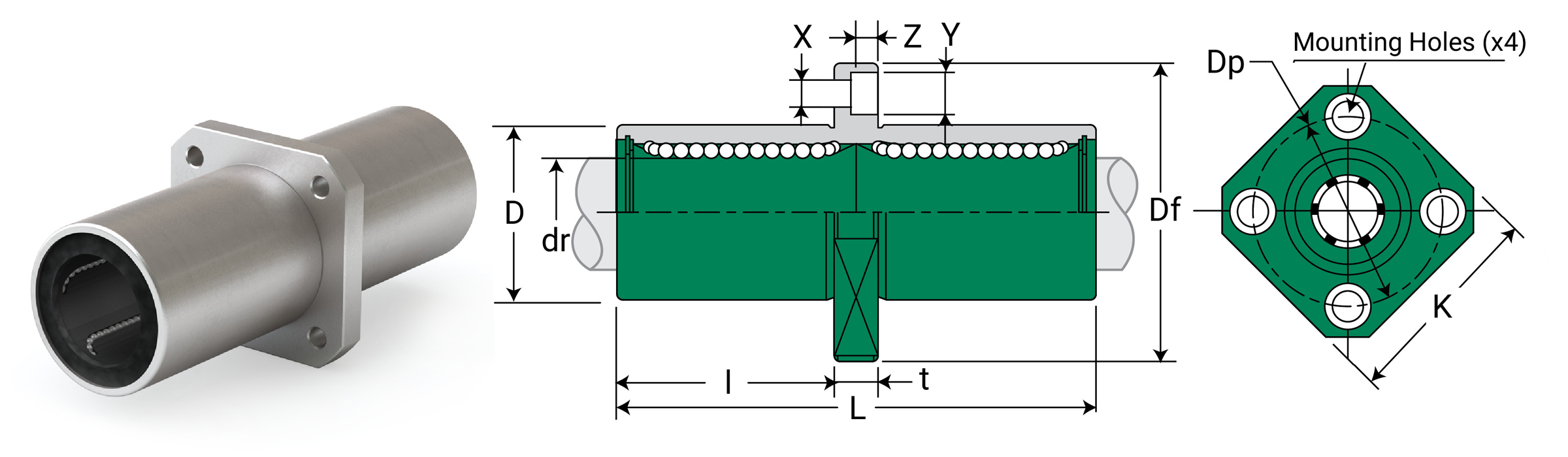
Dimensional Information
| Part No. Standard Polymer Cage |
Nominal Shaft Diameter | Ball Circuit | Weight G |
Major Dimensions & Tolerances | |||||
|---|---|---|---|---|---|---|---|---|---|
| Size mm |
dr mm |
Tolerance µm |
D mm |
Tolerance µm |
L mm |
Tolerance µm |
|||
| JPKC8G | 8 | 8 | 0/-10 | 4 | 43 | 15 | 0/-13 | 45 | ±300 |
| JPKC12G | 12 | 12 | 0/-10 | 4 | 90 | 21 | 0/-16 | 57 | ±300 |
| JPKC16G | 16 | 16 | 0/-10 | 5 | 165 | 28 | 0/-16 | 70 | ±300 |
| JPKC20G | 20 | 20 | 0/-12 | 5 | 225 | 32 | 0/-19 | 80 | ±300 |
| JPKC25G | 25 | 25 | 0/-12 | 6 | 500 | 40 | 0/-19 | 112 | ±300 |
| JPKC30G | 30 | 30 | 0/-12 | 6 | 590 | 45 | 0/-19 | 123 | ±300 |
| JPKC40G | 40 | 40 | 0/-15 | 6 | 1380 | 60 | 0/-22 | 154 | ±300 |
| JPKC50G | 50 | 50 | 0/-15 | 6 | 3400 | 80 | 0/-22 | 192 | ±300 |
| Part No. Standard Polymer Cage |
Nominal Shaft Diameter | Major Dimensions & Tolerances - Flange | Loading Ratings | ||||||||||||
|---|---|---|---|---|---|---|---|---|---|---|---|---|---|---|---|
| Size mm |
dr mm |
Tolerance µm |
I mm |
Df mm |
K mm |
T mm |
Dp mm |
X mm |
Y mm |
Z mm |
Eccentricity µm |
Squareness µm |
Dynamic C N |
Static Co N |
|
| JPKC8G | 8 | 8 | 0/-10 | 20 | 32 | 25 | 5 | 24 | 3.5 | 6.5 | 3.1 | 15 | 15 | 431 | 784 |
| JPKC12G | 12 | 12 | 0/-10 | 25.5 | 42 | 32 | 6 | 32 | 4.5 | 8 | 4.1 | 15 | 15 | 813 | 1570 |
| JPKC16G | 16 | 16 | 0/-10 | 32 | 48 | 37 | 6 | 38 | 4.5 | 8 | 4.1 | 15 | 15 | 1230 | 2350 |
| JPKC20G | 20 | 20 | 0/-12 | 36 | 54 | 42 | 8 | 43 | 5.5 | 9.3 | 5.1 | 20 | 20 | 1400 | 2740 |
| JPKC25G | 25 | 25 | 0/-12 | 52 | 62 | 50 | 8 | 51 | 5.5 | 9.3 | 5.1 | 20 | 20 | 1560 | 3140 |
| JPKC30G | 30 | 30 | 0/-12 | 56.5 | 74 | 58 | 10 | 60 | 6.6 | 11 | 6.1 | 20 | 20 | 2490 | 5490 |
| JPKC40G | 40 | 40 | 0/-15 | 69 | 96 | 75 | 13 | 78 | 9 | 14 | 8.1 | 25 | 25 | 3430 | 8040 |
| JPKC50G | 50 | 50 | 0/-15 | 89.5 | 116 | 92 | 13 | 98 | 9 | 14 | 8.1 | 25 | 25 | 6080 | 15900 |
⚠ Only certified Simplicity 60 Plus Shafting provides maximum bearing performance.
Linear JIS Metric Ball Bearings
Round Flange Center Mount
Ball Bearings – Round Flange Center Mount JPFC
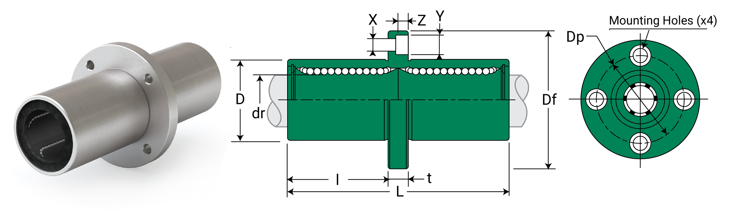
Dimensional Information
| Part No. Standard Polymer Cage |
Nominal Shaft Diameter | Ball Circuit | Weight G |
Major Dimensions & Tolerances | |||||
|---|---|---|---|---|---|---|---|---|---|
| Size mm |
dr mm |
Tolerance µm |
D mm |
Tolerance µm |
L mm |
Tolerance µm |
|||
| JPFC8G | 8 | 8 | 0/-10 | 4 | 51 | 15 | 0/-13 | 45 | ±300 |
| JPFC12G | 12 | 12 | 0/-10 | 4 | 110 | 21 | 0/-16 | 57 | ±300 |
| JPFC16G | 16 | 16 | 0/-10 | 5 | 190 | 28 | 0/-16 | 70 | ±300 |
| JPFC20G | 20 | 20 | 0/-12 | 5 | 260 | 32 | 0/-19 | 80 | ±300 |
| JPFC25G | 25 | 25 | 0/-12 | 6 | 540 | 40 | 0/-19 | 112 | ±300 |
| JPFC30G | 30 | 30 | 0/-12 | 6 | 680 | 45 | 0/-19 | 123 | ±300 |
| JPFC40G | 40 | 40 | 0/-15 | 6 | 1570 | 60 | 0/-22 | 154 | ±300 |
| JPFC50G | 50 | 50 | 0/-15 | 6 | 3600 | 80 | 0/-22 | 192 | ±300 |
| Part No. Standard Polymer Cage |
Nominal Shaft Diameter | Major Dimensions & Tolerances - Flange | Loading Ratings | |||||||||||
|---|---|---|---|---|---|---|---|---|---|---|---|---|---|---|
| Size mm |
dr mm |
Tolerance µm |
I mm |
Df mm |
T mm |
Dp mm |
X mm |
Y mm |
Z mm |
Eccentricity µm |
Squareness µm |
Dynamic C N |
Static Co N |
|
| JPFC8G | 8 | 8 | 0/-10 | 20.0 | 32 | 5 | 24 | 3.5 | 6.5 | 3.1 | 15 | 15 | 431 | 784 |
| JPFC12G | 12 | 12 | 0/-10 | 25.5 | 42 | 6 | 32 | 4.5 | 8 | 4.1 | 15 | 15 | 813 | 1570 |
| JPFC16G | 16 | 16 | 0/-10 | 32.0 | 48 | 6 | 38 | 4.5 | 8 | 4.1 | 15 | 15 | 1230 | 2350 |
| JPFC20G | 20 | 20 | 0/-12 | 36.0 | 54 | 8 | 43 | 5.5 | 9.3 | 5.1 | 20 | 20 | 1400 | 2740 |
| JPFC25G | 25 | 25 | 0/-12 | 52.0 | 62 | 8 | 51 | 5.5 | 9.3 | 5.1 | 20 | 20 | 1560 | 3140 |
| JPFC30G | 30 | 30 | 0/-12 | 56.5 | 74 | 10 | 60 | 6.6 | 11 | 6.1 | 20 | 20 | 2490 | 5490 |
| JPFC40G | 40 | 40 | 0/-15 | 69.0 | 96 | 13 | 78 | 9 | 14 | 8.1 | 25 | 25 | 3430 | 8040 |
| JPFC50G | 50 | 50 | 0/-15 | 89.5 | 116 | 13 | 98 | 9 | 14 | 8.1 | 25 | 25 | 6080 | 15900 |
⚠ Only certified Simplicity 60 Plus Shafting provides maximum bearing performance.
Simplicity Linear Slides Overview
Product Overview
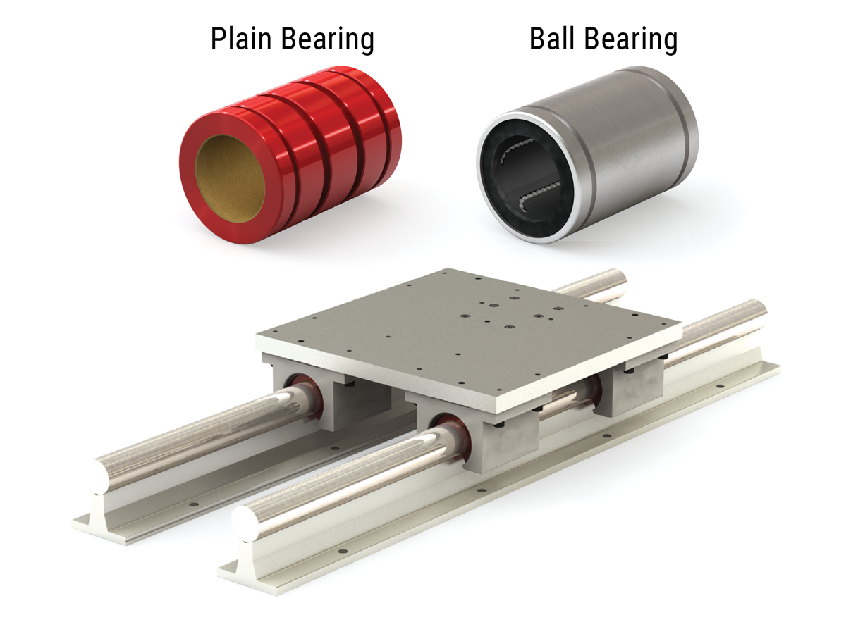
Available with plain or ball bearings, Simplicity slides provide solutions in the toughest environments:
Standard components include:
- Mounting plate
- Four pillow block assemblies
- Two steel shafts
- Two aluminum support rails
Common Applications include:
- Fiberglass manufacturing and processing plants
- Stone cutters and other quarry applications
- Auto manufacturing facilities
- Welding and assembly lines
- Foundries
- Machine tools
Modular Components
- SRB – pre-assembled shaft, rail and bearing
- SRB2 – support rail, guide bar, and two standard Simplicity pillow blocks
- SRBT – support rail, guide bar, and one standard Simplicity pillow block
High Profile
- RS – comes with standard components
- RPS – comes with standard components and includes bottom support plate with precision alignment
- 1RPS – same as RPS with ball screw and one end supported with end plate
- 2RPS – same as RPS with ball screw and both ends supported with end plates
Low Profile
- LRPS – low profile support rail version of a standard RPS
- 2LRPS – low profile support rail version of a standard 2RPS
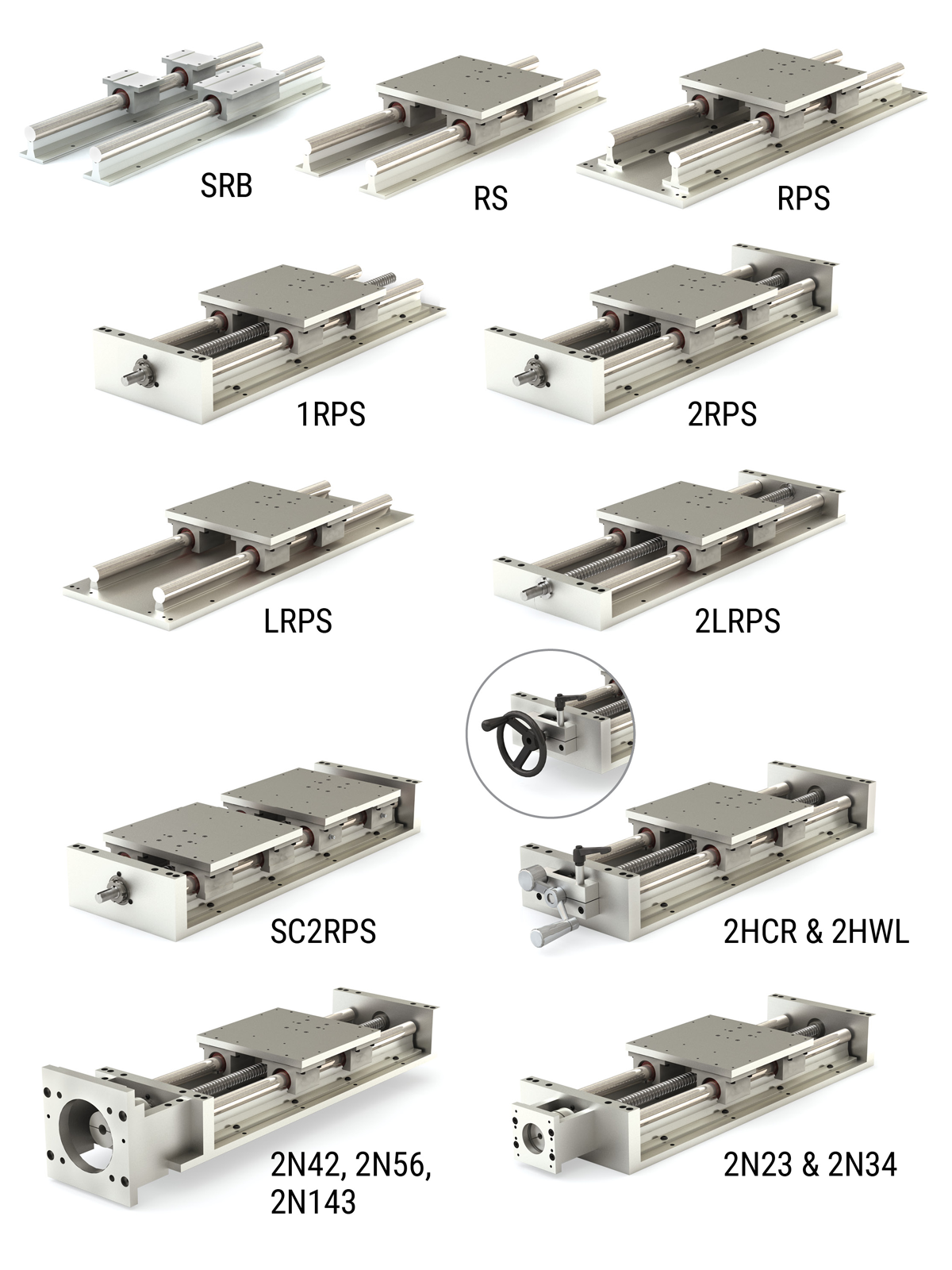
Accessories:
- Hand crank with ball screw lock rotational lock
- Handwheel (foldaway)
- Direct drive NEMA 23 & 34 motor bracket kit
- N42, 56, and 143 bracket options available
4 Lifting Points:
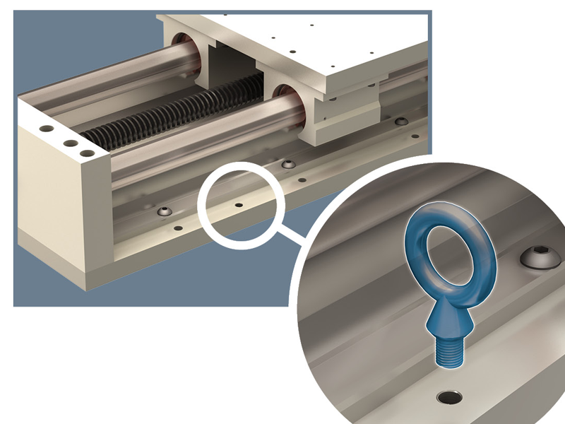
- On all bottom support plates for sizes 20, 24, and 32
- On bottom support plate for sizes 12 and 16 with lengths over 60 inches
- Requires 4 eyebolts of ½-13, not included
Simplicity Linear Slides Assembly
Preassembled Shaft, Rail & Bearing SRB
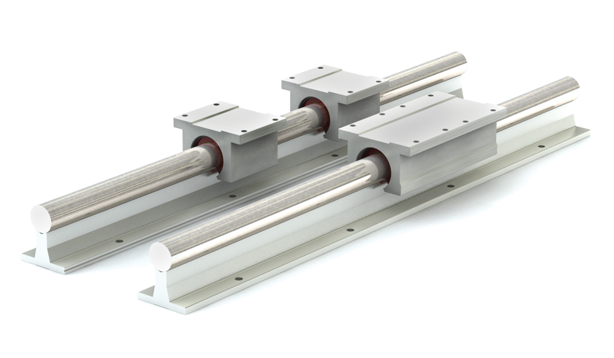
Ordering Example:
To order an assembly with a 0.750" diameter linear shaft, support rail, and one twin double sealed Simplicity bearing with FrelonGOLD®, with a rail length of 96.00", specify part number SRBTD-1200-096.000.
To order an assembly with a 0.625" diameter shaft, support rail, and two single Simplicity bearings without seals, with a rail length of 73.25", specify part number SRB2-1000-073.250.
Note: For lengths over 48", guide bars will be continuous, but rail supports will have a minimum of one break every 48"
Part Number
| Series | Bearing Type | Pillow Block Style | Seals | Internal Lubrication | Size | Shafting Material | Length | ||
| SRB | X | Y | X | XXX | - | 08 | XX | - | XXX.XXX |
Bearing TypeBLANK = Simplicity FrelonGOLD E = Simplicity Frelon® J B = Ball Bearing Pillow Block Style2 = Two single PN bearings 3 = Three single PN bearings C = Compensated T = One Twin PWN bearing T2 = Two Twin PWN bearings S1 = One SST PN bearing S2 = Two SST PN bearings SealsBLANK = None S = Single Seals D = Double Seals Note: “D” double seals are included with standard ball bearings. Internal LubricationBLANK = None (Standard) JKM = Thru hole and internal felt wick Size08 10 12 16 20 24 32 Shaft diameter dimension in 1/16" increments Shafting material00 = Alloy Steel (Standard) CC = Ceramic Coated S3 = 303 Stainless Steel SS = 440 Stainless Steel Note: Ball bearings not suitable with ceramic coated shafting. Rail LengthEnter rail length in inches XXX.XXX (EX: 96" = 096.000) |
Standard Length Table
| Size | Available Rail Lengths - L* (in inches) | ||||||||||||||||||||||||
|---|---|---|---|---|---|---|---|---|---|---|---|---|---|---|---|---|---|---|---|---|---|---|---|---|---|
| 08 | 008 | 012 | 016 | 020 | 024 | 028 | 032 | 036 | 040 | 044 | 048 | 052 | 056 | 060 | 064 | 068 | 072 | 076 | 080 | ||||||
| 10 | 008 | 012 | 016 | 020 | 024 | 028 | 032 | 036 | 040 | 044 | 048 | 052 | 056 | 060 | 064 | 068 | 072 | 076 | 080 | ||||||
| 12 | 012 | 018 | 024 | 030 | 036 | 042 | 048 | 054 | 060 | 066 | 072 | 078 | |||||||||||||
| 16 | 012 | 018 | 024 | 030 | 036 | 042 | 048 | 054 | 060 | 066 | 072 | 078 | |||||||||||||
| 20 | 012 | 018 | 024 | 030 | 036 | 042 | 048 | 054 | 060 | 066 | 072 | 078 | |||||||||||||
| 24 | 016 | 024 | 032 | 040 | 048 | 056 | 064 | 072 | 080 | ||||||||||||||||
| 32 | 024 | 032 | 040 | 048 | 056 | 064 | 072 | 080 | |||||||||||||||||
*Contact factory for longer or non-standard lengths – see non-standard lengths ordering example.
Dimensional Information
| Series | Size | Linear Shaft Dia. |
A | B | C | D | ET | FT | E2 | F2 | G | H | J | K | M | N | P | R | S |
|---|---|---|---|---|---|---|---|---|---|---|---|---|---|---|---|---|---|---|---|
| SRBXY | 08 | 0.500 | 1.125 | 2.00 | 1.688 | 1.50 | 2.50 | 3.50 | 1.000 | 1.687 | 0.250 | 1.812 | 4.00 | 2.00 | 1.125 | 0.156 | 0.169 | 1.000 | 0.188 |
| SRBXY | 10 | 0.625 | 1.125 | 2.50 | 2.125 | 1.62 | 3.00 | 4.00 | 1.125 | 1.937 | 0.281 | 2.000 | 4.00 | 2.00 | 1.437 | 0.188 | 0.193 | 1.125 | 0.250 |
| SRBXY | 12 | 0.750 | 1.500 | 2.75 | 2.375 | 1.75 | 3.50 | 4.50 | 1.250 | 2.062 | 0.312 | 2.438 | 6.00 | 3.00 | 1.562 | 0.188 | 0.221 | 1.250 | 0.250 |
| SRBXY | 16 | 1.000 | 1.750 | 3.25 | 2.875 | 2.12 | 4.50 | 6.00 | 1.750 | 2.812 | 0.375 | 2.938 | 6.00 | 3.00 | 1.937 | 0.219 | 0.281 | 1.500 | 0.250 |
| SRBXY | 20 | 1.250 | 2.125 | 4.00 | 3.500 | 2.50 | 5.50 | 7.50 | 2.000 | 3.625 | 0.437 | 3.625 | 6.00 | 3.00 | 2.500 | 0.219 | 0.343 | 1.875 | 0.312 |
| SRBXY | 24 | 1.500 | 2.500 | 4.75 | 4.125 | 3.00 | 6.50 | 9.00 | 2.500 | 4.000 | 0.500 | 4.250 | 8.00 | 4.00 | 2.875 | 0.281 | 0.343 | 2.250 | 0.375 |
| SRBXY | 32 | 2.000 | 3.250 | 6.00 | 5.250 | 3.75 | 8.25 | 10.00 | 3.250 | 5.000 | 0.625 | 5.375 | 8.00 | 4.00 | 3.625 | 0.406 | 0.406 | 2.750 | 0.500 |
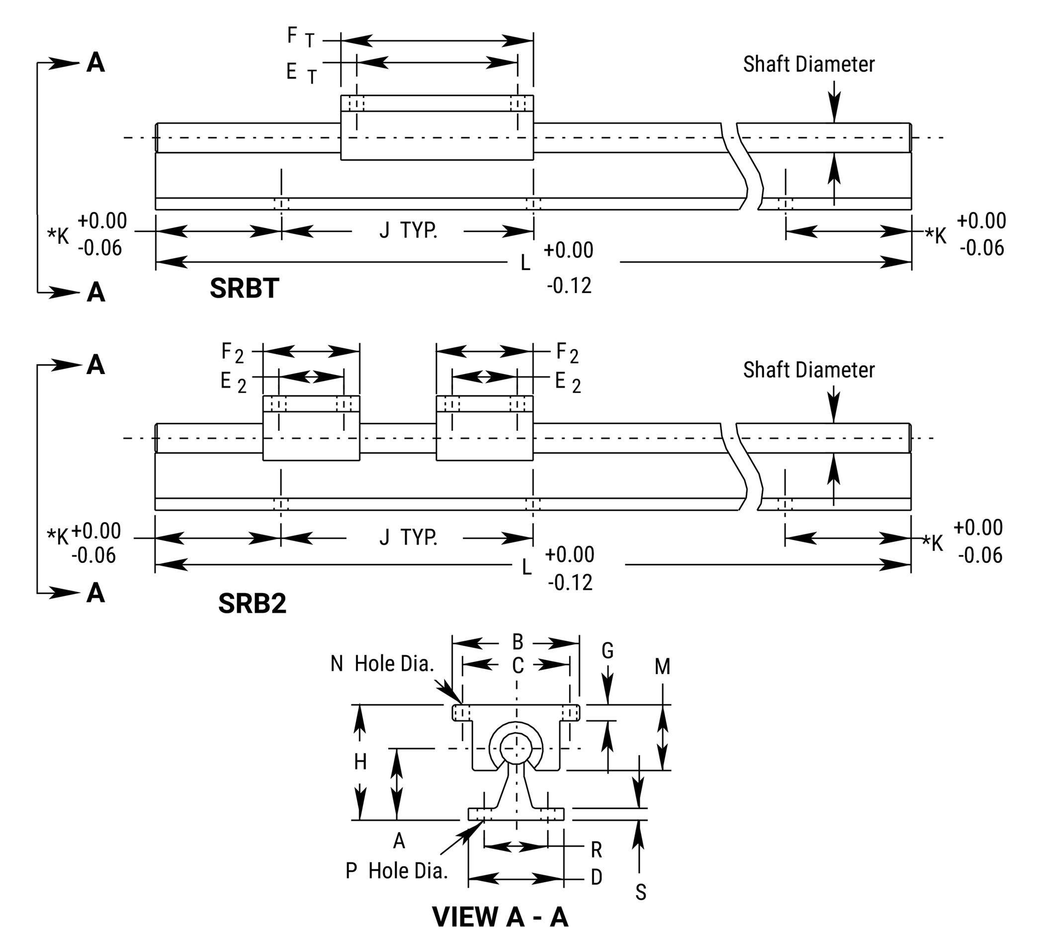
* For standard length dimensions consult chart for “K” dimension.
* For non-standard length dimensions “K” can be calculated with the following formula (in all cases equal on both ends). K (non-std) = (K (from chart) - (∆L/2)). Where ∆L = next longer standard length - desired length.
Simplicity Linear Slides Rail Mounted
Rail Mounted Slide Assembly RS
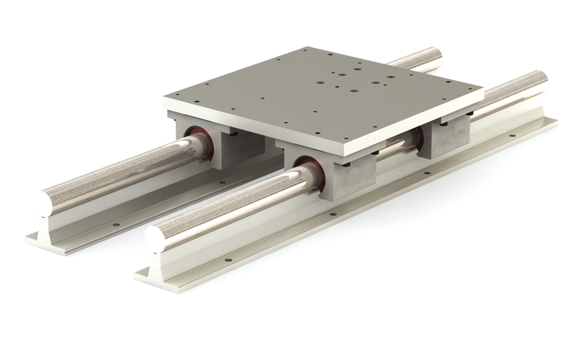
Ordering Example:
To order a slide with a 0.625" diameter alloy steel linear shaft, Simplicity bearings with FrelonGOLD® and 28" rail length, specify part number RS-1000-028.000.
Note: For lengths over 48", guide bars will be continuous, but rail supports will have a minimum of one break every 48". Lengths and mounting provisions to your specifications are available – consult factory.
Part Number
| Series | Bearing Type | Internal Lubrication | Size | Shafting Material | Length | ||
| RS | X | XXX | - | 08 | XX | - | XXX.XXX |
Bearing TypeBLANK = Simplicity FrelonGOLD E = Simplicity Frelon® J B = Ball Bearing Internal LubricationBLANK = None (Standard) JKM = Thru hole and internal felt wick Size08 10 12 16 20 24 32 Shaft diameter dimension in 1/16" increments Shafting material00 = Alloy Steel (Standard) CC = Ceramic Coated S3 = 303 Stainless Steel SS = 440 Stainless Steel Note: Ball bearings not suitable with ceramic coated shafting. Rail LengthEnter rail length in inches XXX.XXX (EX: 28" = 028.000) |
Standard Length Table
| Size | Available Rail Lengths - L* (in inches) | |||||||||||||||||||||||||||||
|---|---|---|---|---|---|---|---|---|---|---|---|---|---|---|---|---|---|---|---|---|---|---|---|---|---|---|---|---|---|---|
| 08 | 008 | 012 | 016 | 020 | 024 | 028 | 032 | 036 | 040 | 044 | 048 | 052 | 056 | 060 | 064 | 068 | 072 | 076 | 080 | 084 | 088 | 092 | 096 | |||||||
| 10 | 008 | 012 | 016 | 020 | 024 | 028 | 032 | 036 | 040 | 044 | 048 | 052 | 056 | 060 | 064 | 068 | 072 | 076 | 080 | 084 | 088 | 092 | 096 | |||||||
| 12 | 012 | 018 | 024 | 030 | 036 | 042 | 048 | 054 | 060 | 066 | 072 | 078 | 084 | 090 | 096 | |||||||||||||||
| 16 | 012 | 018 | 024 | 030 | 036 | 042 | 048 | 054 | 060 | 066 | 072 | 078 | 084 | 090 | 096 | |||||||||||||||
| 20 | 012 | 018 | 024 | 030 | 036 | 042 | 048 | 054 | 060 | 066 | 072 | 078 | 084 | 090 | 096 | |||||||||||||||
| 24 | 016 | 024 | 032 | 040 | 048 | 056 | 064 | 072 | 080 | 088 | 096 | |||||||||||||||||||
| 32 | 024 | 032 | 040 | 048 | 056 | 064 | 072 | 080 | 088 | 096 | ||||||||||||||||||||
*Contact factory for longer or non-standard lengths.
Dimensional Information
| Series | Size | Linear Shaft Dia. |
W | H | A | B | C | D | E | G | J | R | Tap | Hole Dia. |
|---|---|---|---|---|---|---|---|---|---|---|---|---|---|---|
| RS | 08 | 0.500 | 6.00 | 2.188 | 1.125 | 2.00 | 3.50 | 1.500 | 0.375 | 5.500 | 4.00 | 1.000 | 10-24 | 0.17 |
| RS | 10 | 0.625 | 7.00 | 2.375 | 1.125 | 2.50 | 4.00 | 1.625 | 0.375 | 6.312 | 4.00 | 1.125 | 1/4-20 | 0.19 |
| RS | 12 | 0.750 | 8.00 | 2.938 | 1.500 | 2.75 | 4.50 | 1.750 | 0.500 | 7.125 | 6.00 | 1.250 | 1/4-20 | 0.22 |
| RS | 16 | 1.000 | 9.00 | 3.438 | 1.750 | 3.25 | 5.50 | 2.125 | 0.500 | 8.312 | 6.00 | 1.500 | 1/4-20 | 0.28 |
| RS | 20 | 1.250 | 11.00 | 4.375 | 2.125 | 4.00 | 6.50 | 2.500 | 0.750 | 10.000 | 6.00 | 1.875 | 5/16-18 | 0.34 |
| RS | 24 | 1.500 | 13.00 | 5.000 | 2.500 | 4.75 | 8.00 | 3.000 | 0.750 | 12.000 | 8.00 | 2.250 | 5/16-18 | 0.34 |
| RS | 32 | 2.000 | 18.00 | 6.375 | 3.250 | 6.00 | 10.00 | 3.750 | 1.000 | 15.880 | 8.00 | 2.750 | 3/8-16 | 0.41 |
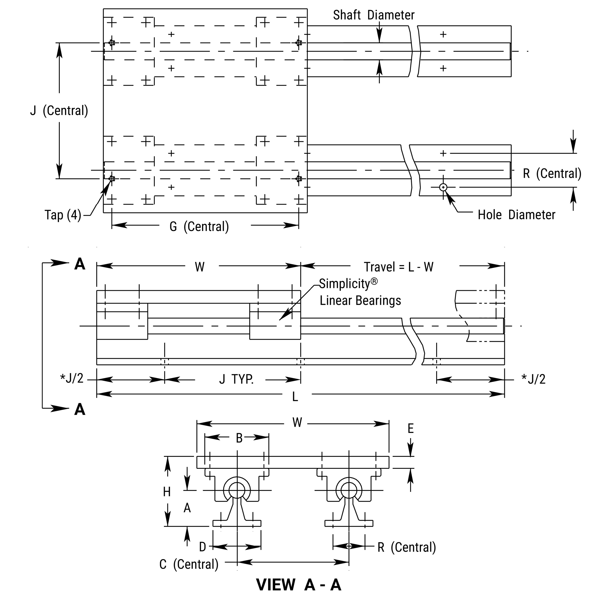
*Hole distance to each end is equal unless specified at time of order
Simplicity Linear Slides Assembly
Rail Mounted & Plate Supported Slide Assembly RPS
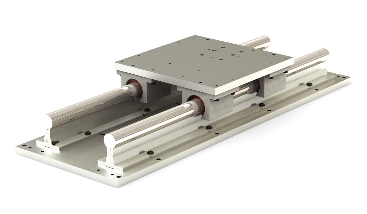
Ordering Example:
To order a slide with a 0.625" diameter alloy steel linear shaft and 28" rail length, specify part number RPS-1000-028.000
Note: For lengths over 48", guide bars will be continuous, but rail supports will have a minimum of one break every 48". Lengths and mounting provisions to your specifications are available – consult factory
Part Number
| Series | Bearing Type | Internal Lubrication | Size | Shafting Material | Length | ||
| RPS | X | XXX | - | 08 | XX | - | XXX.XXX |
Bearing TypeBLANK = Simplicity FrelonGOLD E = Simplicity Frelon® J B = Ball Bearing Internal LubricationBLANK = None (Standard) JKM = Thru hole and internal felt wick Size08 10 12 16 20 24 32 Shaft diameter dimension in 1/16" increments Shafting material00 = Alloy Steel (Standard) CC = Ceramic Coated S3 = 303 Stainless Steel SS = 440 Stainless Steel Note: Ball bearings not suitable with ceramic coated shafting. Rail LengthEnter rail length in inches XXX.XXX (EX: 28" = 028.000) |
Standard Length Table
| Size | Available Rail Lengths - L* (in inches) | |||||||||||||||||||||||||||||
|---|---|---|---|---|---|---|---|---|---|---|---|---|---|---|---|---|---|---|---|---|---|---|---|---|---|---|---|---|---|---|
| 08 | 008 | 012 | 016 | 020 | 024 | 028 | 032 | 036 | 040 | 044 | 048 | 052 | 056 | 060 | 064 | 068 | 072 | 076 | 080 | 084 | 088 | 092 | 096 | |||||||
| 10 | 008 | 012 | 016 | 020 | 024 | 028 | 032 | 036 | 040 | 044 | 048 | 052 | 056 | 060 | 064 | 068 | 072 | 076 | 080 | 084 | 088 | 092 | 096 | |||||||
| 12 | 012 | 018 | 024 | 030 | 036 | 042 | 048 | 054 | 060 | 066 | 072 | 078 | 084 | 090 | 096 | |||||||||||||||
| 16 | 012 | 018 | 024 | 030 | 036 | 042 | 048 | 054 | 060 | 066 | 072 | 078 | 084 | 090 | 096 | |||||||||||||||
| 20 | 012 | 018 | 024 | 030 | 036 | 042 | 048 | 054 | 060 | 066 | 072 | 078 | 084 | 090 | 096 | |||||||||||||||
| 24 | 016 | 024 | 032 | 040 | 048 | 056 | 064 | 072 | 080 | 088 | 096 | |||||||||||||||||||
| 32 | 024 | 032 | 040 | 048 | 056 | 064 | 072 | 080 | 088 | 096 | ||||||||||||||||||||
*Contact factory for longer or non-standard lengths.
Dimensional Information
| Series | Size | Linear Shaft Dia. |
W | H | A | B | C | D | E | G | J | R | Tap | Hole Dia. |
|---|---|---|---|---|---|---|---|---|---|---|---|---|---|---|
| RPS | 08 | 0.500 | 6.00 | 2.562 | 1.125 | 2.00 | 3.50 | 1.500 | 0.375 | 1.00 | 5.500 | 4.00 | 10-24 | 0.22 |
| RPS | 10 | 0.625 | 7.00 | 2.750 | 1.125 | 2.50 | 4.00 | 1.625 | 0.375 | 1.00 | 6.312 | 4.00 | 1/4-20 | 0.28 |
| RPS | 12 | 0.750 | 8.00 | 3.438 | 1.500 | 2.75 | 4.50 | 1.750 | 0.500 | 1.25 | 7.125 | 6.00 | 1/4-20 | 0.28 |
| RPS | 16 | 1.000 | 9.00 | 3.938 | 1.750 | 3.25 | 5.50 | 2.125 | 0.500 | 1.25 | 8.312 | 6.00 | 1/4-20 | 0.28 |
| RPS | 20 | 1.250 | 11.00 | 5.125 | 2.125 | 4.00 | 6.50 | 2.500 | 0.750 | 1.50 | 10.000 | 6.00 | 5/16-18 | 0.34 |
| RPS | 24 | 1.500 | 13.00 | 5.750 | 2.500 | 4.75 | 8.00 | 3.000 | 0.750 | 1.50 | 12.000 | 8.00 | 5/16-18 | 0.34 |
| RPS | 32 | 2.000 | 18.00 | 7.375 | 3.250 | 6.00 | 10.00 | 3.750 | 1.000 | 1.75 | 15.875 | 8.00 | 3/8-16 | 0.41 |
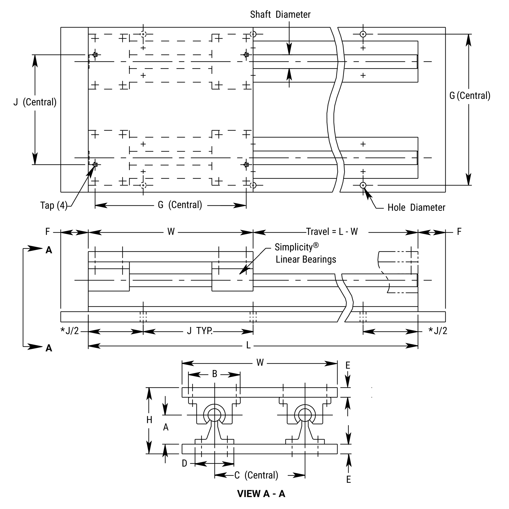
*Hole distance to each end is equal unless specified at time of order
Simplicity Linear Slides
One End Support
Rail Mounted & Plate Supported – Ball Screw Driven 1RPS
SUPPORTED ON ONE END
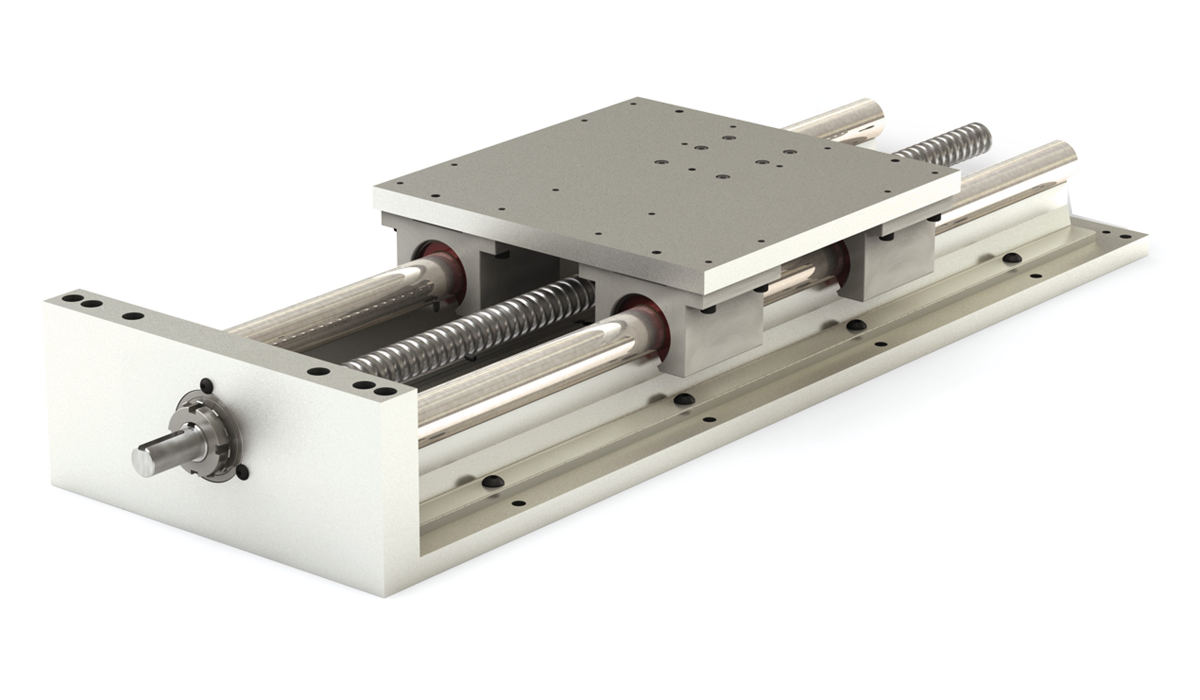
Ordering Example:
To order a slide with a 0.625" diameter 440 stainless steel linear shaft, 28" rail length, 0.200" right hand select ball screw, specify part number 1RPS-10SS-028.000-AA7R.
Part Number
| Series | Bearing Type | Internal Lubrication | Size | Shafting Material | Length | Lead | |||
| 1RPS | X | XXX | - | 08 | XX | - | XXX.XXX | - | YYYY |
Bearing TypeBLANK = Simplicity FrelonGOLD E = Simplicity Frelon® J B = Ball Bearing Internal LubricationBLANK = None (Standard) JKM = Thru hole and internal felt wick Size08 10 12 16 20 24 32 Shaft diameter dimension in 1/16" increments Shafting material00 = Alloy Steel (Standard) CC = Ceramic Coated S3 = 303 Stainless Steel SS = 440 Stainless Steel Note: Ball bearings not suitable with ceramic coated shafting. Rail LengthEnter rail length in inches XXX.XXX (EX: 28" = 028.000) LeadSubstitute standard or select lead code from table for “YYYY” |
Standard Lead Table
Accurate to less than 0.007" per foot accumulative
| Size | Available Lead Codes | ||||||
|---|---|---|---|---|---|---|---|
| 08 | AAXR | AAXL | |||||
| 10 | AAXR | AAXL | |||||
| 12 | AAXR | AAXL | |||||
| 16 | ABXR | ABXL | ACXR | ADXR | |||
| 20 | ABXR | ABXL | ACXR | ADXR | |||
| 24 | ABXR | ABXL | ACXR | ADXR | ADXL | ||
| 32 | ABXR | ABXL | ACXR | ADXR | ADXL | ||
AAXR = 0.20 Right Hand
AAXL = 0.20 Left Hand
ABXR = 0.25 Right Hand
ABXL = 0.25 Left Hand
ACXR = 0.50 Right Hand
ADXR = 1.00 Right Hand
ADXL = 1.00 Left Hand
Note: Additional leads available upon request.
Select Lead Table
Accurate to less than 0.003" per foot accumulative
| Size | Available Lead Codes | ||||||
|---|---|---|---|---|---|---|---|
| 08 | AA7R | AA7L | |||||
| 10 | AA7R | AA7L | |||||
| 12 | AA7R | AA7L | |||||
| 16 | AB7R | AB7L | AC7R | AD7R | |||
| 20 | AB7R | AB7L | AC7R | AD7R | |||
| 24 | AB7R | AB7L | AC7R | AD7R | AD7L | ||
| 32 | AB7R | AB7L | AC7R | AD7R | AD7L | ||
AA7R = 0.20 Right Hand
AA7L = 0.20 Left Hand
AB7R = 0.25 Right Hand
AB7L = 0.25 Left Hand
AC7R = 0.50 Right Hand
AD7R = 1.00 Right Hand
AD7L = 1.00 Left Hand
Note: Additional leads available upon request.
Standard Length Table
| Size | Available Rail Lengths - L* (in inches) | ||||||||||||
|---|---|---|---|---|---|---|---|---|---|---|---|---|---|
| 08 | 008 | 012 | 016 | 020 | 024 | 028 | 032 | ||||||
| 10 | 008 | 012 | 016 | 020 | 024 | 028 | 032 | ||||||
| 12 | 012 | 018 | 024 | 030 | 036 | 042 | |||||||
| 16 | 012 | 018 | 024 | 030 | 036 | 042 | |||||||
| 20 | 012 | 018 | 024 | 030 | 036 | 042 | 048 | ||||||
| 24 | 016 | 024 | 032 | 040 | 048 | ||||||||
| 32 | 024 | 032 | 040 | 048 | |||||||||
*Contact factory for longer or non-standard lengths.
Dimensional Information
| Series | Size | Linear Shaft Dia. |
W | H | A | B | C | D | E | F | G | J | K | M | N | O | Tap | Hole Dia. | Key |
|---|---|---|---|---|---|---|---|---|---|---|---|---|---|---|---|---|---|---|---|
| 1RPS | 08 | 0.500 | 6.00 | 2.562 | 1.125 | 2.00 | 3.50 | 1.500 | 0.375 | 1.00 | 5.500 | 4.00 | 1.375 | 0.375 | 1.45 | 0.63 | 10-24 | 0.22 | 3/32 sq x 5/8 lg |
| 1RPS | 10 | 0.625 | 7.00 | 2.750 | 1.125 | 2.50 | 4.00 | 1.625 | 0.375 | 1.00 | 6.312 | 4.00 | 1.375 | 0.375 | 1.45 | 0.63 | 1/4-20 | 0.28 | 3/32 sq x 5/8 lg |
| 1RPS | 12 | 0.750 | 8.00 | 3.438 | 1.500 | 2.75 | 4.50 | 1.750 | 0.500 | 1.25 | 7.125 | 6.00 | 1.500 | 0.375 | 1.45 | 0.63 | 1/4-20 | 0.28 | 3/32 sq x 5/8 lg |
| 1RPS | 16 | 1.000 | 9.00 | 3.938 | 1.750 | 3.25 | 5.50 | 2.125 | 0.500 | 1.25 | 8.312 | 6.00 | 2.125 | 0.625 | 1.76 | 1.00 | 1/4-20 | 0.28 | 3/16 sq x 1" lg |
| 1RPS | 20 | 1.250 | 11.00 | 5.125 | 2.125 | 4.00 | 6.50 | 2.500 | 0.750 | 1.50 | 10.000 | 6.00 | 2.375 | 0.625 | 1.76 | 1.00 | 5/16-18 | 0.34 | 3/16 sq x 1” lg |
| 1RPS | 24 | 1.500 | 13.00 | 5.750 | 2.500 | 4.75 | 8.00 | 3.000 | 0.750 | 1.50 | 12.000 | 8.00 | 2.875 | 0.875 | 2.31 | 1.50 | 5/16-18 | 0.34 | 1/4 sq x 1.62 lg |
| 1RPS | 32 | 2.000 | 18.00 | 7.375 | 3.250 | 6.00 | 10.00 | 3.750 | 1.000 | 1.75 | 15.875 | 8.00 | 3.875 | 0.875 | 2.31 | 1.50 | 3/8-16 | 0.41 | 1/4 sq x 1.62 lg |
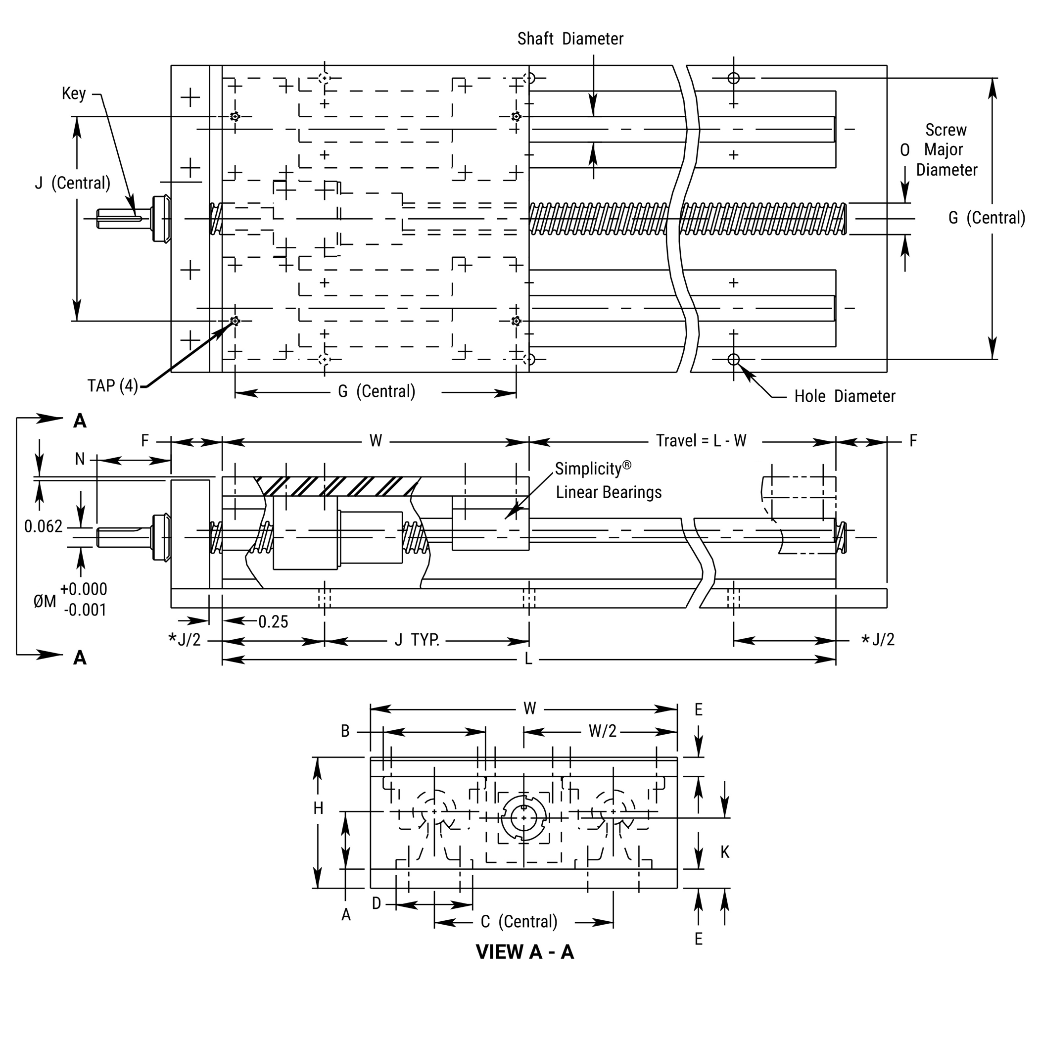
*Hole distance to each end is equal unless specified at time of order
Simplicity Linear Slides
Both Ends Supported
Rail Mounted & Plate Supported – Ball Screw Driven 2RPS
SUPPORTED ON BOTH ENDS
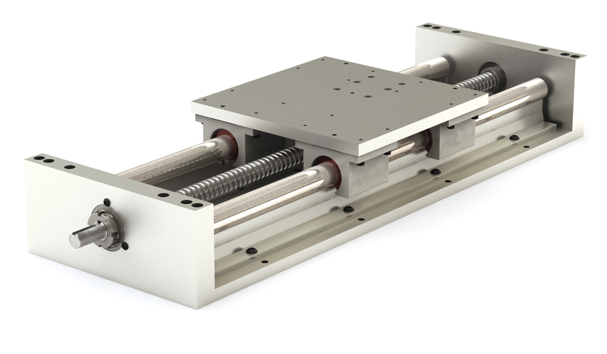
Ordering Example:
To order a slide with a 0.625" diameter alloy steel linear shaft, 28" rail length, 0.200" right hand select ball screw, specify part number 2RPS-1000-028.000-AA7R.
Part Number
| Series | Bearing Type | Internal Lubrication | Size | Shafting Material | Length | Lead | |||
| 2RPS | X | XXX | - | 08 | XX | - | XXX.XXX | - | YYYY |
Bearing TypeBLANK = Simplicity FrelonGOLD E = Simplicity Frelon® J B = Ball Bearing Internal LubricationBLANK = None (Standard) JKM = Thru hole and internal felt wick Size08 10 12 16 20 24 32 Shaft diameter dimension in 1/16" increments Shafting material00 = Alloy Steel (Standard) CC = Ceramic Coated S3 = 303 Stainless Steel SS = 440 Stainless Steel Note: Ball bearings not suitable with ceramic coated shafting. Rail LengthEnter rail length in inches XXX.XXX (EX: 28" = 028.000) LeadSubstitute standard or select lead code from table for “YYYY” |
Standard Lead Table
Accurate to less than 0.007" per foot accumulative
| Size | Available Lead Codes | ||||||
|---|---|---|---|---|---|---|---|
| 08 | AAXR | AAXL | |||||
| 10 | AAXR | AAXL | |||||
| 12 | AAXR | AAXL | |||||
| 16 | ABXR | ABXL | ACXR | ADXR | |||
| 20 | ABXR | ABXL | ACXR | ADXR | |||
| 24 | ABXR | ABXL | ACXR | ADXR | ADXL | ||
| 32 | ABXR | ABXL | ACXR | ADXR | ADXL | ||
AAXR = 0.20 Right Hand
AAXL = 0.20 Left Hand
ABXR = 0.25 Right Hand
ABXL = 0.25 Left Hand
ACXR = 0.50 Right Hand
ADXR = 1.00 Right Hand
ADXL = 1.00 Left Hand
Note: Additional leads available upon request.
Select Lead Table
Accurate to less than 0.003" per foot accumulative
| Size | Available Lead Codes | ||||||
|---|---|---|---|---|---|---|---|
| 08 | AA7R | AA7L | |||||
| 10 | AA7R | AA7L | |||||
| 12 | AA7R | AA7L | |||||
| 16 | AB7R | AB7L | AC7R | AD7R | |||
| 20 | AB7R | AB7L | AC7R | AD7R | |||
| 24 | AB7R | AB7L | AC7R | AD7R | AD7L | ||
| 32 | AB7R | AB7L | AC7R | AD7R | AD7L | ||
AA7R = 0.20 Right Hand
AA7L = 0.20 Left Hand
AB7R = 0.25 Right Hand
AB7L = 0.25 Left Hand
AC7R = 0.50 Right Hand
AD7R = 1.00 Right Hand
AD7L = 1.00 Left Hand
Note: Additional leads available upon request.
Standard Length Table
| Size | Available Rail Lengths - L* (in inches) | |||||||||||||||||||||||||||||
|---|---|---|---|---|---|---|---|---|---|---|---|---|---|---|---|---|---|---|---|---|---|---|---|---|---|---|---|---|---|---|
| 08 | 008 | 012 | 016 | 020 | 024 | 028 | 032 | 036 | 040 | 044 | 048 | 052 | 056 | 060 | 064 | 068 | 072 | 076 | 080 | 084 | 088 | 092 | 096 | |||||||
| 10 | 008 | 012 | 016 | 020 | 024 | 028 | 032 | 036 | 040 | 044 | 048 | 052 | 056 | 060 | 064 | 068 | 072 | 076 | 080 | 084 | 088 | 092 | 096 | |||||||
| 12 | 012 | 018 | 024 | 030 | 036 | 042 | 048 | 054 | 060 | 066 | 072 | 078 | 084 | 090 | 096 | |||||||||||||||
| 16 | 012 | 018 | 024 | 030 | 036 | 042 | 048 | 054 | 060 | 066 | 072 | 078 | 084 | 090 | 096 | |||||||||||||||
| 20 | 012 | 018 | 024 | 030 | 036 | 042 | 048 | 054 | 060 | 066 | 072 | 078 | 084 | 090 | 096 | |||||||||||||||
| 24 | 016 | 024 | 032 | 040 | 048 | 056 | 064 | 072 | 080 | 088 | 096 | |||||||||||||||||||
| 32 | 024 | 032 | 040 | 048 | 056 | 064 | 072 | 080 | 088 | 096 | ||||||||||||||||||||
*Contact factory for longer or non-standard lengths.
Dimensional Information
| Series | Size | Linear Shaft Dia. |
W | H | A | B | C | D | E | F | G | J | K | M | N | O | Tap | Hole Dia. | Key |
|---|---|---|---|---|---|---|---|---|---|---|---|---|---|---|---|---|---|---|---|
| 2RPS | 08 | 0.500 | 6.00 | 2.562 | 1.125 | 2.00 | 3.50 | 1.500 | 0.375 | 1.00 | 5.500 | 4.00 | 1.375 | 0.375 | 1.45 | 0.63 | 10-24 | 0.22 | 3/32 sq x 5/8 lg |
| 2RPS | 10 | 0.625 | 7.00 | 2.750 | 1.125 | 2.50 | 4.00 | 1.625 | 0.375 | 1.00 | 6.312 | 4.00 | 1.375 | 0.375 | 1.45 | 0.63 | 1/4-20 | 0.28 | 3/32 sq x 5/8 lg |
| 2RPS | 12 | 0.750 | 8.00 | 3.438 | 1.500 | 2.75 | 4.50 | 1.750 | 0.500 | 1.25 | 7.125 | 6.00 | 1.500 | 0.375 | 1.45 | 0.63 | 1/4-20 | 0.28 | 3/32 sq x 5/8 lg |
| 2RPS | 16 | 1.000 | 9.00 | 3.938 | 1.750 | 3.25 | 5.50 | 2.125 | 0.500 | 1.25 | 8.312 | 6.00 | 2.125 | 0.625 | 1.76 | 1.00 | 1/4-20 | 0.28 | 3/16 sq x 1" lg |
| 2RPS | 20 | 1.250 | 11.00 | 5.125 | 2.125 | 4.00 | 6.50 | 2.500 | 0.750 | 1.50 | 10.000 | 6.00 | 2.375 | 0.625 | 1.76 | 1.00 | 5/16-18 | 0.34 | 3/16 sq x 1” lg |
| 2RPS | 24 | 1.500 | 13.00 | 5.750 | 2.500 | 4.75 | 8.00 | 3.000 | 0.750 | 1.50 | 12.000 | 8.00 | 2.875 | 0.875 | 2.31 | 1.50 | 5/16-18 | 0.34 | 1/4 sq x 1.62 lg |
| 2RPS | 32 | 2.000 | 18.00 | 7.375 | 3.250 | 6.00 | 10.00 | 3.750 | 1.000 | 1.75 | 15.875 | 8.00 | 3.875 | 0.875 | 2.31 | 1.50 | 3/8-16 | 0.41 | 1/4 sq x 1.62 lg |
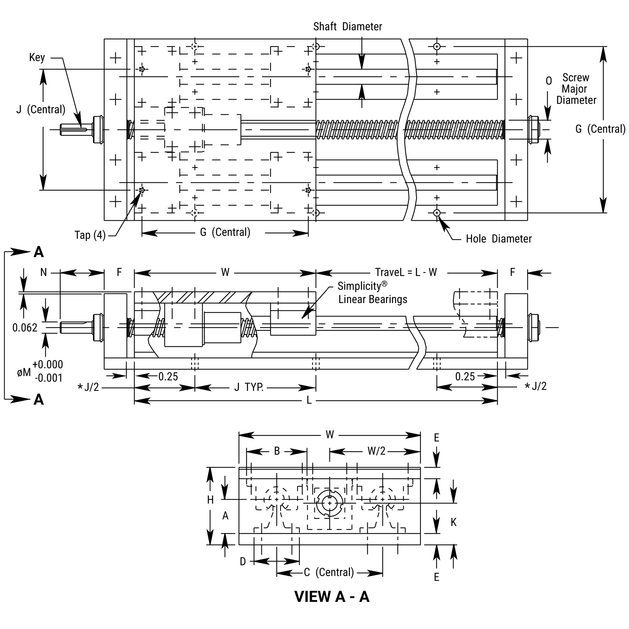
*Hole distance to each end is equal unless specified at time of order
Simplicity Linear Slides Low Profile
Rail Mounted & Plate Supported Slide Assembly LRPS
LOW PROFILE
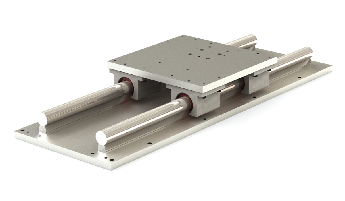
Ordering Example:
To order a slide with a 0.625" diameter alloy steel linear shaft and 28" rail length, specify part number LRPS-1000-028.000.
Part Number
| Series | Bearing Type | Internal Lubrication | Size | Shafting Material | Length | ||
| LRPS | X | XXX | - | 08 | XX | - | XXX.XXX |
Bearing TypeBLANK = Simplicity FrelonGOLD E = Simplicity Frelon® J B = Ball Bearing Internal LubricationBLANK = None (Standard) JKM = Thru hole and internal felt wick Size08 10 12 16 20 24 32 Shaft diameter dimension in 1/16" increments Shafting material00 = Alloy Steel (Standard) CC = Ceramic Coated S3 = 303 Stainless Steel SS = 440 Stainless Steel Note: Ball bearings not suitable with ceramic coated shafting. Rail LengthEnter rail length in inches XXX.XXX (EX: 28" = 028.000) |
Standard Length Table
| Size | Available Rail Lengths - L* (in inches) | |||||||||||||||||||||||||||||
|---|---|---|---|---|---|---|---|---|---|---|---|---|---|---|---|---|---|---|---|---|---|---|---|---|---|---|---|---|---|---|
| 08 | 008 | 012 | 016 | 020 | 024 | 028 | 032 | 036 | 040 | 044 | 048 | 052 | 056 | 060 | 064 | 068 | 072 | 076 | 080 | 084 | 088 | 092 | 096 | |||||||
| 10 | 008 | 012 | 016 | 020 | 024 | 028 | 032 | 036 | 040 | 044 | 048 | 052 | 056 | 060 | 064 | 068 | 072 | 076 | 080 | 084 | 088 | 092 | 096 | |||||||
| 12 | 012 | 018 | 024 | 030 | 036 | 042 | 048 | 054 | 060 | 066 | 072 | 078 | 084 | 090 | 096 | |||||||||||||||
| 16 | 012 | 018 | 024 | 030 | 036 | 042 | 048 | 054 | 060 | 066 | 072 | 078 | 084 | 090 | 096 | |||||||||||||||
| 20 | 012 | 018 | 024 | 030 | 036 | 042 | 048 | 054 | 060 | 066 | 072 | 078 | 084 | 090 | 096 | |||||||||||||||
| 24 | 016 | 024 | 032 | 040 | 048 | 056 | 064 | 072 | 080 | 088 | 096 | |||||||||||||||||||
| 32 | 024 | 032 | 040 | 048 | 056 | 064 | 072 | 080 | 088 | 096 | ||||||||||||||||||||
*Contact factory for longer or non-standard lengths.
Dimensional Information
| Series | Size | Linear Shaft Dia. |
W | H | A | B | C | D | E | F | G | J | Tap | Hole Dia. |
|---|---|---|---|---|---|---|---|---|---|---|---|---|---|---|
| LRPS | 08 | 0.500 | 6.00 | 2.000 | 0.563 | 2.00 | 3.50 | 0.37 | 0.375 | 1.00 | 5.500 | 4.00 | 10-24 | 0.22 |
| LRPS | 10 | 0.625 | 7.00 | 2.313 | 0.688 | 2.50 | 4.00 | 0.45 | 0.375 | 1.00 | 6.312 | 4.00 | 1/4-20 | 0.28 |
| LRPS | 12 | 0.750 | 8.00 | 2.688 | 0.750 | 2.75 | 4.50 | 0.51 | 0.500 | 1.25 | 7.125 | 6.00 | 1/4-20 | 0.28 |
| LRPS | 16 | 1.000 | 9.00 | 3.188 | 1.000 | 3.25 | 5.50 | 0.69 | 0.500 | 1.25 | 8.312 | 6.00 | 1/4-20 | 0.28 |
| LRPS | 20 | 1.250 | 11.00 | 4.188 | 1.188 | 4.00 | 6.50 | 0.78 | 0.750 | 1.50 | 10.000 | 6.00 | 5/16-18 | 0.34 |
| LRPS | 24 | 1.500 | 13.00 | 4.625 | 1.375 | 4.75 | 8.00 | 0.93 | 0.750 | 1.50 | 12.000 | 8.00 | 5/16-18 | 0.34 |
| LRPS | 32 | 2.000 | 18.00 | 5.875 | 1.750 | 6.00 | 10.00 | 1.18 | 1.000 | 1.75 | 15.875 | 8.00 | 3/8-16 | 0.41 |
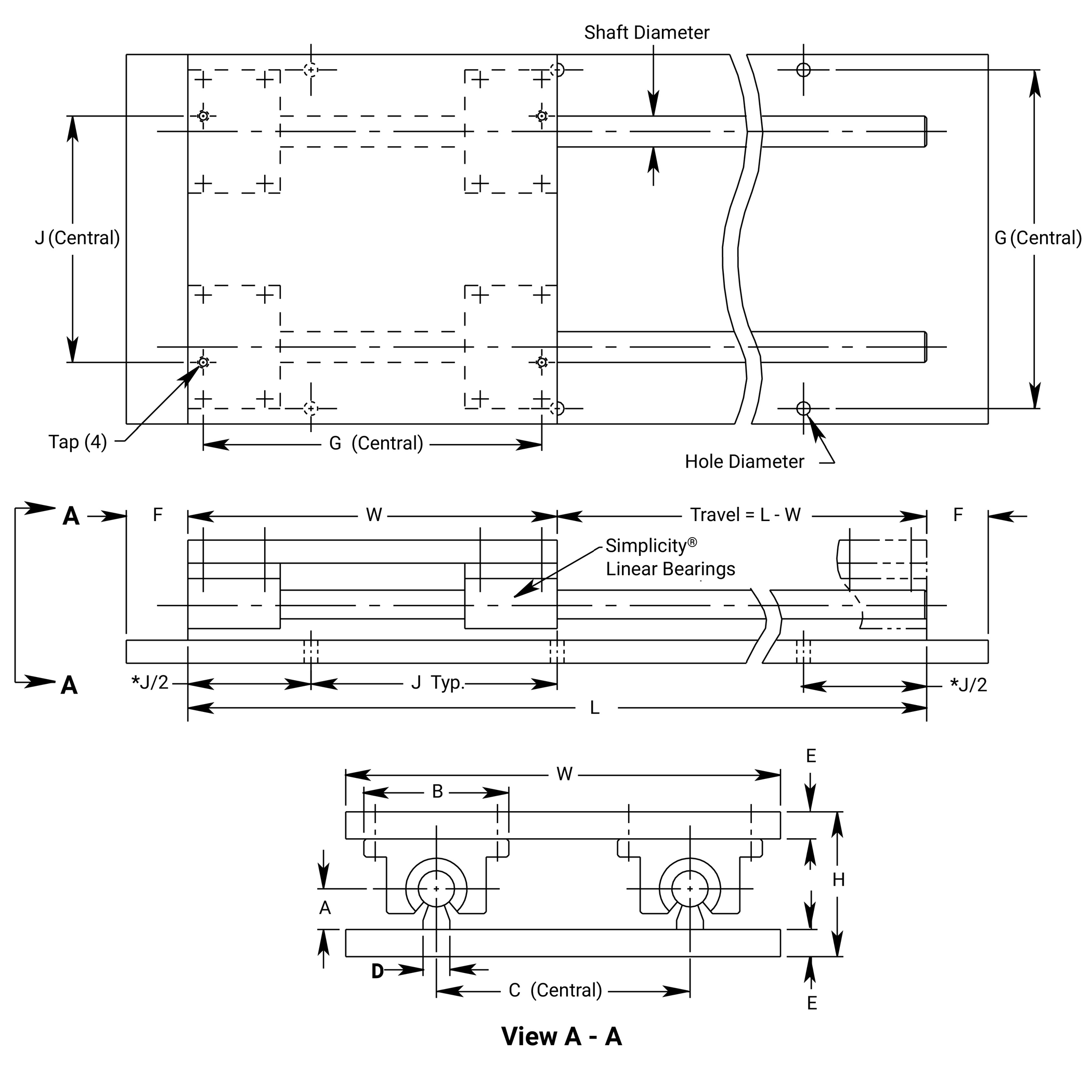
*Hole distance to each end is equal unless specified at time of order
Simplicity Linear Slides Low Profile
Ball Screw
Rail Mounted & Plate Ball Screw Driven 2LRPS
LOW PROFILE - SUPPORTED ON BOTH ENDS
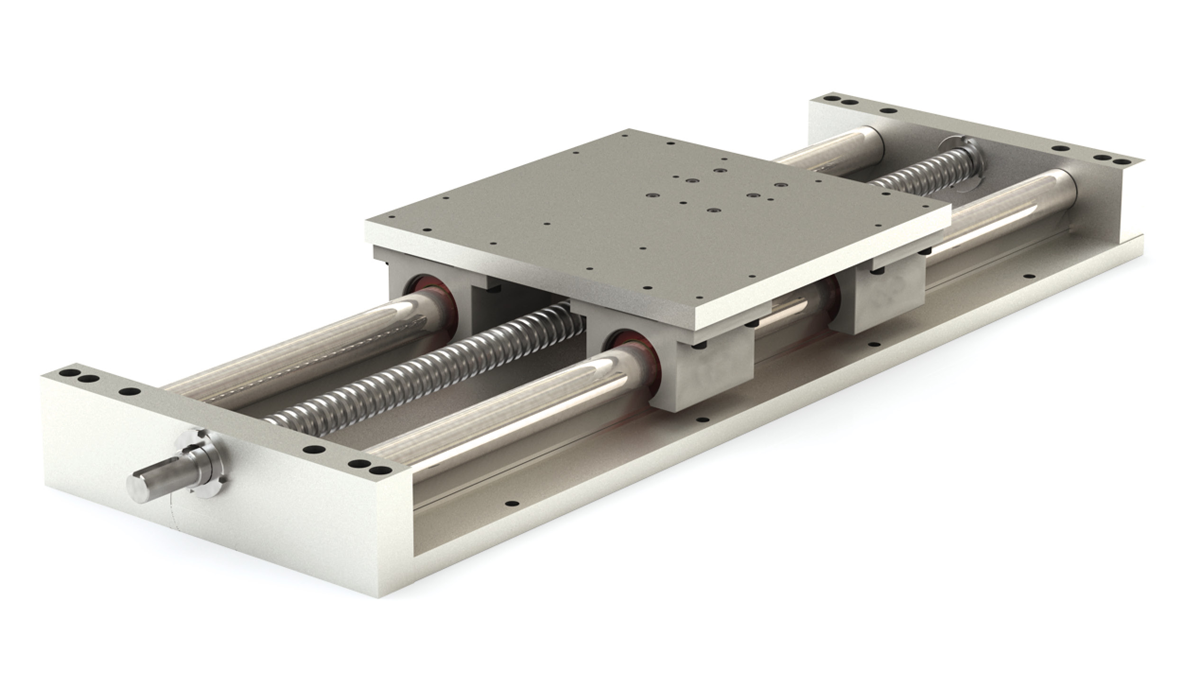
Ordering Example:
To order a slide with a 0.625" diameter alloy steel linear shaft, 28" rail length, 0.200" right hand select ball screw – specify part number, 2LRPS-1000-028.000-AA7R.
Part Number
| Series | Bearing Type | Internal Lubrication | Size | Shafting Material | Length | Lead | |||
| 2LRPS | X | XXX | - | 08 | XX | - | XXX.XXX | - | YYYY |
Bearing TypeBLANK = Simplicity FrelonGOLD E = Simplicity Frelon® J B = Ball Bearing Internal LubricationBLANK = None (Standard) JKM = Thru hole and internal felt wick Size08 10 12 16 20 24 32 Shaft diameter dimension in 1/16" increments Shafting material00 = Alloy Steel (Standard) CC = Ceramic Coated S3 = 303 Stainless Steel SS = 440 Stainless Steel Note: Ball bearings not suitable with ceramic coated shafting. Rail LengthEnter rail length in inches XXX.XXX (EX: 28" = 028.000) LeadSubstitute standard or select lead code from table for “YYYY” |
Standard Lead Table
Accurate to less than 0.007" per foot accumulative
| Size | Available Lead Codes | ||||||
|---|---|---|---|---|---|---|---|
| 08 | AAXR | AAXL | |||||
| 10 | AAXR | AAXL | |||||
| 12 | AAXR | AAXL | |||||
| 16 | ABXR | ABXL | ACXR | ADXR | |||
| 20 | ABXR | ABXL | ACXR | ADXR | |||
| 24 | ABXR | ABXL | ACXR | ADXR | ADXL | ||
| 32 | ABXR | ABXL | ACXR | ADXR | ADXL | ||
AAXR = 0.20 Right Hand
AAXL = 0.20 Left Hand
ABXR = 0.25 Right Hand
ABXL = 0.25 Left Hand
ACXR = 0.50 Right Hand
ADXR = 1.00 Right Hand
ADXL = 1.00 Left Hand
Note: Additional leads available upon request.
Select Lead Table
Accurate to less than 0.003" per foot accumulative
| Size | Available Lead Codes | ||||||
|---|---|---|---|---|---|---|---|
| 08 | AA7R | AA7L | |||||
| 10 | AA7R | AA7L | |||||
| 12 | AA7R | AA7L | |||||
| 16 | AB7R | AB7L | AC7R | AD7R | |||
| 20 | AB7R | AB7L | AC7R | AD7R | |||
| 24 | AB7R | AB7L | AC7R | AD7R | AD7L | ||
| 32 | AB7R | AB7L | AC7R | AD7R | AD7L | ||
AA7R = 0.20 Right Hand
AA7L = 0.20 Left Hand
AB7R = 0.25 Right Hand
AB7L = 0.25 Left Hand
AC7R = 0.50 Right Hand
AD7R = 1.00 Right Hand
AD7L = 1.00 Left Hand
Note: Additional leads available upon request.
Standard Length Table
| Size | Available Rail Lengths - L* (in inches) | |||||||||||||||||||||||||||||
|---|---|---|---|---|---|---|---|---|---|---|---|---|---|---|---|---|---|---|---|---|---|---|---|---|---|---|---|---|---|---|
| 08 | 008 | 012 | 016 | 020 | 024 | 028 | 032 | 036 | 040 | 044 | 048 | 052 | 056 | 060 | 064 | 068 | 072 | 076 | 080 | 084 | 088 | 092 | 096 | |||||||
| 10 | 008 | 012 | 016 | 020 | 024 | 028 | 032 | 036 | 040 | 044 | 048 | 052 | 056 | 060 | 064 | 068 | 072 | 076 | 080 | 084 | 088 | 092 | 096 | |||||||
| 12 | 012 | 018 | 024 | 030 | 036 | 042 | 048 | 054 | 060 | 066 | 072 | 078 | 084 | 090 | 096 | |||||||||||||||
| 16 | 012 | 018 | 024 | 030 | 036 | 042 | 048 | 054 | 060 | 066 | 072 | 078 | 084 | 090 | 096 | |||||||||||||||
| 20 | 012 | 018 | 024 | 030 | 036 | 042 | 048 | 054 | 060 | 066 | 072 | 078 | 084 | 090 | 096 | |||||||||||||||
| 24 | 016 | 024 | 032 | 040 | 048 | 056 | 064 | 072 | 080 | 088 | 096 | |||||||||||||||||||
| 32 | 024 | 032 | 040 | 048 | 056 | 064 | 072 | 080 | 088 | 096 | ||||||||||||||||||||
*Contact factory for longer or non-standard lengths.
Dimensional Information
| Series | Size | Linear Shaft. Dia | W | H | A | B | C | D | E | F | G | J | K | M | N | O | Tap | Hole Dia. | Key |
|---|---|---|---|---|---|---|---|---|---|---|---|---|---|---|---|---|---|---|---|
| 2LRPS | 08 | 0.500 | 6.00 | 2.000 | 0.563 | 2.00 | 3.50 | 0.37 | 0.375 | 1.00 | 5.500 | 4.00 | 1.000 | 0.375 | 1.45 | 0.63 | 10-24 | 0.22 | 3/32 sq x 5/8 lg |
| 2LRPS | 10 | 0.625 | 7.00 | 2.313 | 0.688 | 2.50 | 4.00 | 0.45 | 0.375 | 1.00 | 6.312 | 4.00 | 1.156 | 0.375 | 1.45 | 0.63 | 1/4-20 | 0.28 | 3/32 sq x 5/8 lg |
| 2LRPS | 12 | 0.750 | 8.00 | 2.688 | 0.750 | 2.75 | 4.50 | 0.51 | 0.500 | 1.25 | 7.125 | 6.00 | 1.344 | 0.375 | 1.45 | 0.63 | 1/4-20 | 0.28 | 3/32 sq x 5/8 lg |
| 2LRPS | 16 | 1.000 | 9.00 | 3.188 | 1.000 | 3.25 | 5.50 | 0.69 | 0.500 | 1.25 | 8.312 | 6.00 | 1.594 | 0.625 | 1.76 | 1.00 | 1/4-20 | 0.28 | 3/16 sq x 1" lg |
| 2LRPS | 20 | 1.250 | 11.00 | 4.188 | 1.188 | 4.00 | 6.50 | 0.78 | 0.750 | 1.50 | 10.000 | 6.00 | 2.094 | 0.625 | 1.76 | 1.00 | 5/16-18 | 0.34 | 3/16 sq x 1” lg |
| 2LRPS | 24 | 1.500 | 13.00 | 4.625 | 1.375 | 4.75 | 8.00 | 0.93 | 0.750 | 1.50 | 12.000 | 8.00 | 2.312 | 0.875 | 2.31 | 1.50 | 5/16-18 | 0.34 | 1/4 sq x 1.62 lg |
| 2LRPS | 32 | 2.000 | 18.00 | 5.875 | 1.750 | 6.00 | 10.00 | 1.18 | 1.000 | 1.75 | 15.875 | 8.00 | 2.937 | 0.875 | 2.31 | 1.50 | 3/8-16 | 0.41 | 1/4 sq x 1.62 lg |
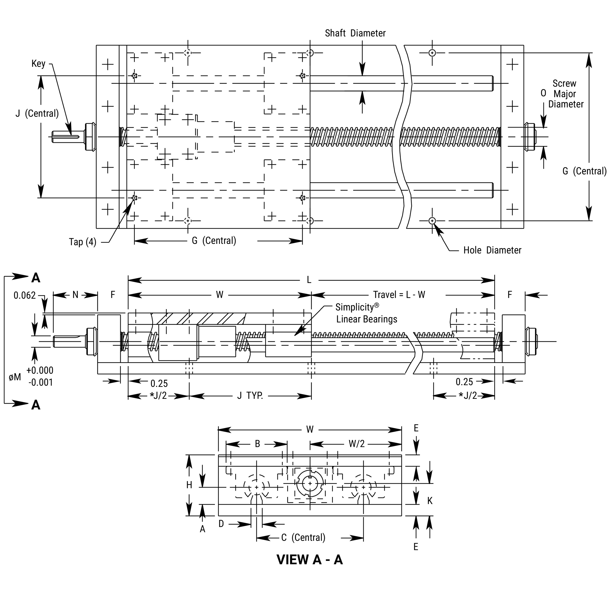
*Hole distance to each end is equal unless specified at time of order
Simplicity Linear Slides Self Centering
Self-Centering Slide Assembly SC2RPS
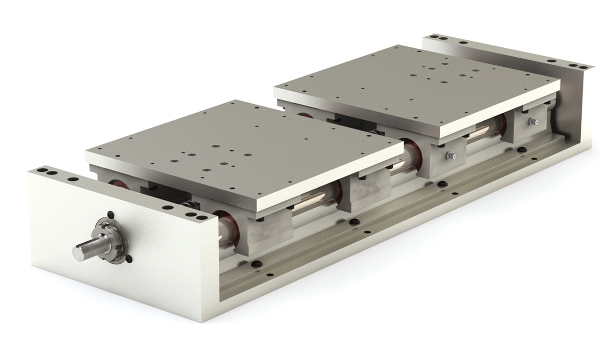
Ordering Example:
To order a slide with a 0.625" diameter alloy steel linear shaft, 56" rail length, 0.200" right hand select lead screw – specify part number, SC2RPS-1000-056.000-AA7LR.
Part Number
| Series | Bearing Type | Internal Lubrication | Size | Shafting Material | Length | Lead | |||
| SC2RPS | X | XXX | - | 08 | XX | - | XXX.XXX | - | YYYY |
Bearing TypeBLANK = Simplicity FrelonGOLD E = Simplicity Frelon® J B = Ball Bearing Internal LubricationBLANK = None (Standard) JKM = Thru hole and internal felt wick Size08 10 12 16 20 24 32 Shaft diameter dimension in 1/16" increments Shafting material00 = Alloy Steel (Standard) CC = Ceramic Coated S3 = 303 Stainless Steel SS = 440 Stainless Steel Note: Ball bearings not suitable with ceramic coated shafting. Rail LengthEnter rail length in inches XXX.XXX (EX: 28" = 028.000) LeadSubstitute standard or select lead code from table for “YYYY” |
Standard Lead Table
Accurate to less than 0.007" per foot accumulative
| Size | Available Lead Codes | ||
|---|---|---|---|
| 08 | AAXLR | ||
| 10 | AAXLR | ||
| 12 | AAXLR | ||
| 16 | ABXLR | ||
| 20 | ABXLR | ||
| 24 | ABXLR | ADXLR | |
| 32 | ABXLR | ADXLR | |
AAXLR = 0.20 Leads
ABXLR = 0.25 Leads
ADXLR = 1.00 Leads
One left and one right hand lead ballscrew on each self-centering slide assembly.
Note: Additional leads available upon request.
Select Lead Table
Accurate to less than 0.003" per foot accumulative
| Size | Available Lead Codes | ||
|---|---|---|---|
| 08 | AA7LR | ||
| 10 | AA7LR | ||
| 12 | AA7LR | ||
| 16 | AB7LR | ||
| 20 | AB7LR | ||
| 24 | AB7LR | AD7LR | |
| 32 | AB7LR | AD7LR | |
AA7LR = 0.20 Leads
AB7LR = 0.25 Leads
AD7LR = 1.00 Leads
One left and one right hand lead ballscrew on each self-centering slide assembly.
Note: Additional leads available upon request.
Standard Length Table
| Size | Available Rail Lengths - L* (in inches) | |||||||||||||||||||||||||||||
|---|---|---|---|---|---|---|---|---|---|---|---|---|---|---|---|---|---|---|---|---|---|---|---|---|---|---|---|---|---|---|
| 08 | 016 | 020 | 024 | 028 | 032 | 036 | 040 | 044 | 048 | 052 | 056 | 060 | 064 | 068 | 072 | 076 | 080 | 084 | 088 | 092 | 096 | |||||||||
| 10 | 016 | 020 | 024 | 028 | 032 | 036 | 040 | 044 | 048 | 052 | 056 | 060 | 064 | 068 | 072 | 076 | 080 | 084 | 088 | 092 | 096 | |||||||||
| 12 | 018 | 024 | 030 | 036 | 042 | 048 | 054 | 060 | 066 | 072 | 078 | 084 | 090 | 096 | ||||||||||||||||
| 16 | 024 | 030 | 036 | 042 | 048 | 054 | 060 | 066 | 072 | 078 | 084 | 090 | 096 | |||||||||||||||||
| 20 | 024 | 030 | 036 | 042 | 048 | 054 | 060 | 066 | 072 | 078 | 084 | 090 | 096 | |||||||||||||||||
| 24 | 032 | 040 | 048 | 056 | 064 | 072 | 080 | 088 | 096 | |||||||||||||||||||||
| 32 | 040 | 048 | 056 | 064 | 072 | 080 | 088 | 096 | ||||||||||||||||||||||
*Contact factory for longer or non-standard lengths.
Dimensional Information
| Series | Size | Linear Shaft. Dia | W | H | A | B | C | D | E | F | G | J | K | M | N | O | Tap | Hole Dia. | Key |
|---|---|---|---|---|---|---|---|---|---|---|---|---|---|---|---|---|---|---|---|
| SC2RPS | 08 | 0.500 | 6.00 | 2.562 | 1.125 | 2.00 | 3.50 | 1.500 | 0.375 | 1.00 | 5.500 | 4.00 | 1.375 | 0.375 | 1.45 | 0.63 | 10-24 | 0.22 | 3/32 sq x 5/8 lg |
| SC2RPS | 10 | 0.625 | 7.00 | 2.750 | 1.125 | 2.50 | 4.00 | 1.625 | 0.375 | 1.00 | 6.312 | 4.00 | 1.375 | 0.375 | 1.45 | 0.63 | 1/4-20 | 0.28 | 3/32 sq x 5/8 lg |
| SC2RPS | 12 | 0.750 | 8.00 | 3.438 | 1.500 | 2.75 | 4.50 | 1.750 | 0.500 | 1.25 | 7.125 | 6.00 | 1.500 | 0.375 | 1.45 | 0.63 | 1/4-20 | 0.28 | 3/32 sq x 5/8 lg |
| SC2RPS | 16 | 1.000 | 9.00 | 3.938 | 1.750 | 3.25 | 5.50 | 2.125 | 0.500 | 1.25 | 8.312 | 6.00 | 2.125 | 0.625 | 1.76 | 1.00 | 1/4-20 | 0.28 | 3/16 sq x 1" lg |
| SC2RPS | 20 | 1.250 | 11.00 | 5.125 | 2.125 | 4.00 | 6.50 | 2.500 | 0.750 | 1.50 | 10.000 | 6.00 | 2.375 | 0.625 | 1.76 | 1.00 | 5/16-18 | 0.34 | 3/16 sq x 1” lg |
| SC2RPS | 24 | 1.500 | 13.00 | 5.750 | 2.500 | 4.75 | 8.00 | 3.000 | 0.750 | 1.50 | 12.000 | 8.00 | 2.875 | 0.875 | 2.31 | 1.50 | 5/16-18 | 0.34 | 1/4 sq x 1.62 lg |
| SC2RPS | 32 | 2.000 | 18.00 | 7.375 | 3.250 | 6.00 | 10.00 | 3.750 | 1.000 | 1.75 | 15.875 | 8.00 | 3.875 | 0.875 | 2.31 | 1.50 | 3/8-16 | 0.41 | 1/4 sq x 1.62 lg |
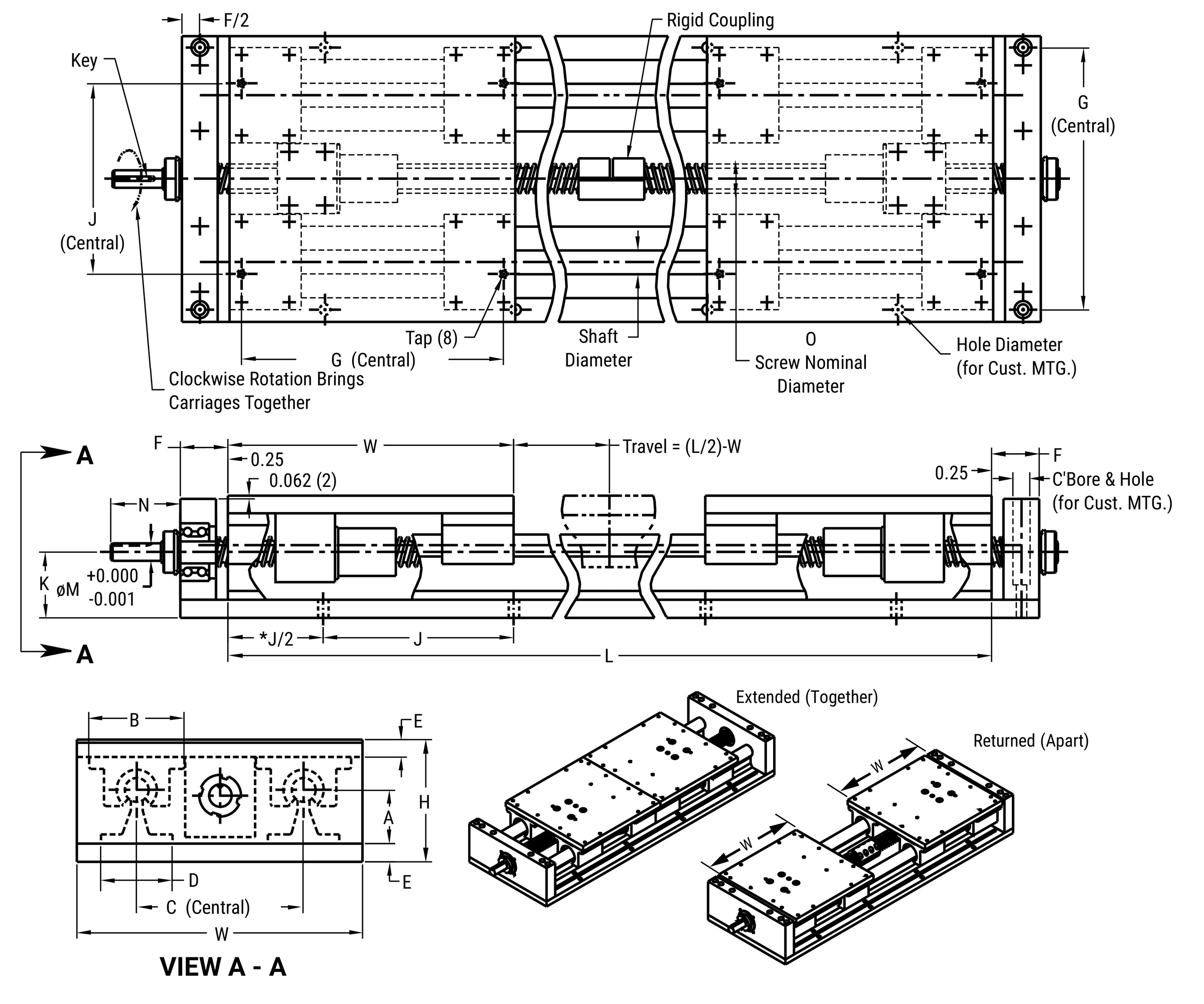
*Hole distance to each end is equal unless specified at time of order
Simplicity Linear Slides
Handcrank & Wheel
Slide Assembly with Hand Crank & Ball Screw Rotational Lock 2HCR & 2HWL
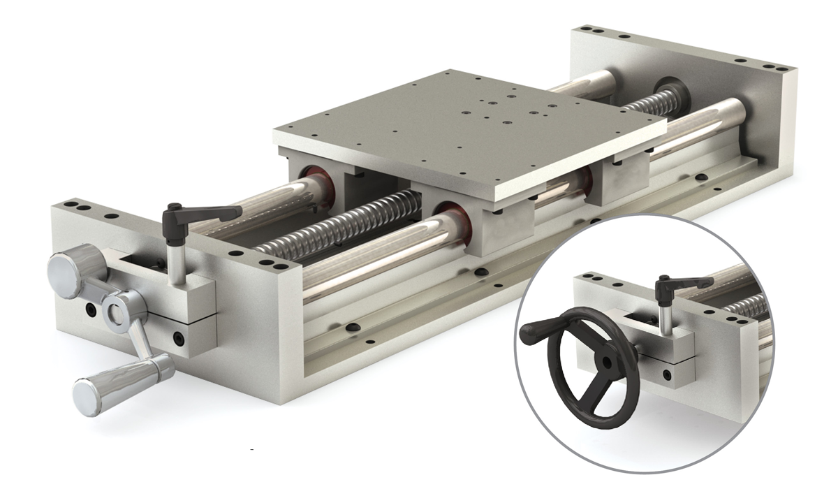
Ordering Example:
To order a slide with a 0.625" diameter alloy steel linear shaft, 28" rail length, 0.200" right hand select ball screw and a hand wheel –specify part number, 2HWL-1000-028.000-AA7R.
Part Number
| Series | Handle Type | Bearing Type | Internal Lubrication | Size | Shafting Material | Length | Lead | |||
| 2H | XX | X | XXX | - | 08 | XX | - | XXX.XXX | - | YYYY |
Handle TypeCR = Standard Model WL = Deluxe Model Bearing TypeBLANK = Simplicity FrelonGOLD E = Simplicity Frelon® J B = Ball Bearing Internal LubricationBLANK = None (Standard) JKM = Thru hole and internal felt wick Size08 10 12 16 20 24 32 Shaft diameter dimension in 1/16" increments Shafting material00 = Alloy Steel (Standard) CC = Ceramic Coated S3 = 303 Stainless Steel SS = 440 Stainless Steel Note: Ball bearings not suitable with ceramic coated shafting. Rail LengthEnter rail length in inches XXX.XXX (EX: 28" = 028.000) LeadSubstitute standard or select lead code from table for “YYYY” |
Standard Lead Table
Accurate to less than 0.007" per foot accumulative
| Size | Available Lead Codes | ||||||
|---|---|---|---|---|---|---|---|
| 08 | AAXR | AAXL | |||||
| 10 | AAXR | AAXL | |||||
| 12 | AAXR | AAXL | |||||
| 16 | ABXR | ABXL | ACXR | ADXR | |||
| 20 | ABXR | ABXL | ACXR | ADXR | |||
| 24 | ABXR | ABXL | ACXR | ADXR | ADXL | ||
| 32 | ABXR | ABXL | ACXR | ADXR | ADXL | ||
AAXR = 0.20 Right Hand
AAXL = 0.20 Left Hand
ABXR = 0.25 Right Hand
ABXL = 0.25 Left Hand
ACXR = 0.50 Right Hand
ADXR = 1.00 Right Hand
ADXL = 1.00 Left Hand
Note: Additional leads available upon request.
Select Lead Table
Accurate to less than 0.003" per foot accumulative
| Size | Available Lead Codes | ||||||
|---|---|---|---|---|---|---|---|
| 08 | AA7R | AA7L | |||||
| 10 | AA7R | AA7L | |||||
| 12 | AA7R | AA7L | |||||
| 16 | AB7R | AB7L | AC7R | AD7R | |||
| 20 | AB7R | AB7L | AC7R | AD7R | |||
| 24 | AB7R | AB7L | AC7R | AD7R | AD7L | ||
| 32 | AB7R | AB7L | AC7R | AD7R | AD7L | ||
AA7R = 0.20 Right Hand
AA7L = 0.20 Left Hand
AB7R = 0.25 Right Hand
AB7L = 0.25 Left Hand
AC7R = 0.50 Right Hand
AD7R = 1.00 Right Hand
AD7L = 1.00 Left Hand
Note: Additional leads available upon request.
Standard Length Table
| Size | Available Rail Lengths - L* (in inches) | |||||||||||||||||||||||||||||
|---|---|---|---|---|---|---|---|---|---|---|---|---|---|---|---|---|---|---|---|---|---|---|---|---|---|---|---|---|---|---|
| 08 | 008 | 012 | 016 | 020 | 024 | 028 | 032 | 036 | 040 | 044 | 048 | 052 | 056 | 060 | 064 | 068 | 072 | 076 | 080 | 084 | 088 | 092 | 096 | |||||||
| 10 | 008 | 012 | 016 | 020 | 024 | 028 | 032 | 036 | 040 | 044 | 048 | 052 | 056 | 060 | 064 | 068 | 072 | 076 | 080 | 084 | 088 | 092 | 096 | |||||||
| 12 | 012 | 018 | 024 | 030 | 036 | 042 | 048 | 054 | 060 | 066 | 072 | 078 | 084 | 090 | 096 | |||||||||||||||
| 16 | 012 | 018 | 024 | 030 | 036 | 042 | 048 | 054 | 060 | 066 | 072 | 078 | 084 | 090 | 096 | |||||||||||||||
| 20 | 012 | 018 | 024 | 030 | 036 | 042 | 048 | 054 | 060 | 066 | 072 | 078 | 084 | 090 | 096 | |||||||||||||||
| 24 | 016 | 024 | 032 | 040 | 048 | 056 | 064 | 072 | 080 | 088 | 096 | |||||||||||||||||||
| 32 | 024 | 032 | 040 | 048 | 056 | 064 | 072 | 080 | 088 | 096 | ||||||||||||||||||||
*Contact factory for longer or non-standard lengths.
Dimensional Information
| Series | Size | Linear Shaft. Dia | W | H | A | B | C | D | E | F | G | J | K | O | P | Q | R | S | T | U | V | X | Y | Z | Tap | Hole Dia. |
|---|---|---|---|---|---|---|---|---|---|---|---|---|---|---|---|---|---|---|---|---|---|---|---|---|---|---|
| 2HXX | 08 | 0.500 | 6 | 2.562 | 1.125 | 2.00 | 3.5 | 1.500 | 0.375 | 0.75 | 5.500 | 4.00 | 1.375 | 0.631 | 2.56 | 3.85 | 3.00 | 0.875 | 1.312 | 4.00 | 4 | 4 | 2.655 | 4.855 | 10-24 | 0.22 |
| 2HXX | 10 | 0.625 | 7 | 2.750 | 1.125 | 2.50 | 4.0 | 1.625 | 0.375 | 0.75 | 6.312 | 4.00 | 1.375 | 0.631 | 2.56 | 3.85 | 3.00 | 0.875 | 1.312 | 4.00 | 4 | 4 | 2.655 | 4.855 | 1/4-20 | 0.28 |
| 2HXX | 12 | 0.750 | 8 | 3.438 | 1.500 | 2.75 | 4.5 | 1.750 | 0.500 | 1.00 | 7.125 | 6.00 | 1.500 | 0.631 | 2.56 | 3.85 | 3.00 | 0.875 | 1.312 | 4.00 | 4 | 4 | 2.655 | 4.855 | 1/4-20 | 0.28 |
| 2HXX | 16 | 1.000 | 9 | 3.938 | 1.750 | 3.25 | 5.5 | 2.125 | 0.500 | 1.00 | 8.312 | 6.00 | 2.125 | 1.000 | 2.56 | 3.69 | 4.25 | 1.125 | 2.000 | 4.25 | 5 | 6 | 3.185 | 5.745 | 1/4-20 | 0.28 |
| 2HXX | 20 | 1.250 | 11 | 5.125 | 2.125 | 4.00 | 6.5 | 2.500 | 0.750 | 1.25 | 10.000 | 6.00 | 2.375 | 1.000 | 2.56 | 3.69 | 4.25 | 1.125 | 2.000 | 4.25 | 5 | 6 | 3.185 | 5.745 | 5/16-18 | 0.34 |
| 2HXX | 24 | 1.500 | 13 | 5.750 | 2.500 | 4.75 | 8.0 | 3.000 | 0.750 | 1.25 | 12.000 | 8.00 | 2.875 | 1.500 | 3.15 | 5.81 | 6.50 | 1.500 | 3.000 | 6.90 | 8 | 8 | 4.310 | 7.460 | 5/16-18 | 0.34 |
| 2HXX | 32 | 2.000 | 18 | 7.375 | 3.250 | 6.00 | 10.0 | 3.750 | 1.000 | 1.50 | 15.875 | 8.00 | 3.875 | 1.500 | 3.15 | 5.81 | 6.50 | 1.500 | 3.000 | 6.90 | 8 | 8 | 4.310 | 7.460 | 3/8-16 | 0.41 |
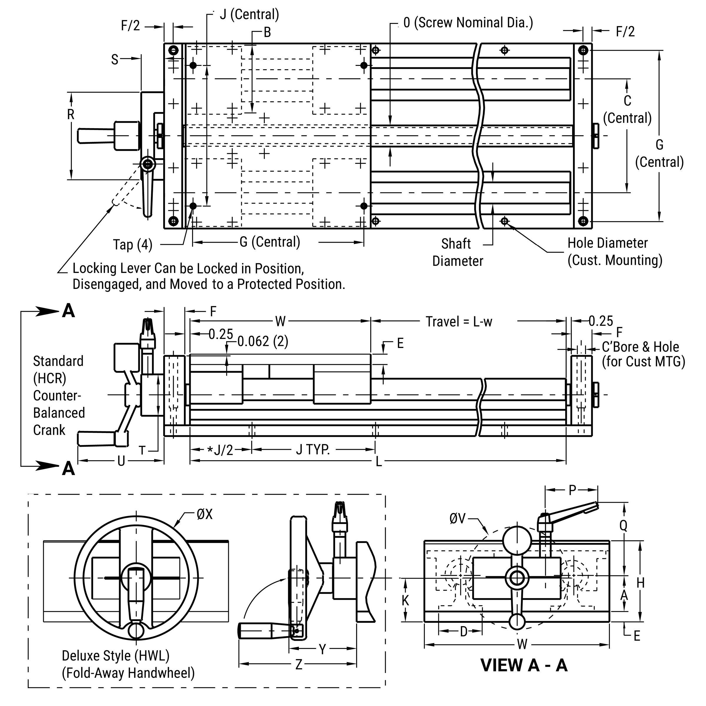
*Hole distance to each end is equal unless specified at time of order
Simplicity Linear Slides
Nema Drive Kit
Slide Assembly & Nema Drive Kit 2N42, 56, 143
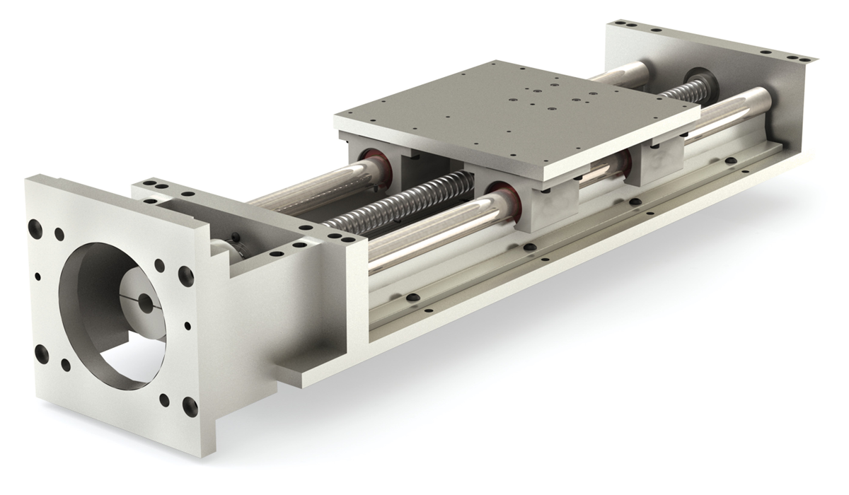
Ordering Example:
To order a slide with a 1" diameter alloy steel linear shaft, 28" rail length, 0.250" right hand select ball screw, and a NEMA 56 motor with a 0.625" shaft – specify part number, 2N56-1600-028.000-AB7R.
Part Number
| Series | Motor Mount | Bearing Type | Internal Lubrication | Size | Shafting Material | Length | Lead | |||
| 2N | XX | X | XXX | - | 16 | XX | - | XXX.XXX | - | YYYY |
Motor Mounting DimensionsSee Motor Mounting Dimensions Table Below Bearing TypeBLANK = Simplicity FrelonGOLD E = Simplicity Frelon® J B = Ball Bearing Internal LubricationBLANK = None (Standard) JKM = Thru hole and internal felt wick Size16 20 24 32 Shaft diameter dimension in 1/16" increments Shafting material00 = Alloy Steel (Standard) CC = Ceramic Coated S3 = 303 Stainless Steel SS = 440 Stainless Steel Note: Ball bearings not suitable with ceramic coated shafting. Rail LengthEnter rail length in inches XXX.XXX (EX: 28" = 028.000) LeadSubstitute standard or select lead code from table for “YYYY” |
Standard Lead Table
Accurate to less than 0.007" per foot accumulative
| Size | Available Lead Codes | ||||||
|---|---|---|---|---|---|---|---|
| 16 | ABXR | ABXL | ACXR | ADXR | |||
| 20 | ABXR | ABXL | ACXR | ADXR | |||
| 24 | ABXR | ABXL | ACXR | ADXR | ADXL | ||
| 32 | ABXR | ABXL | ACXR | ADXR | ADXL | ||
ABXR = 0.25 Right Hand
ABXL = 0.25 Left Hand
ACXR = 0.50 Right Hand
ADXR = 1.00 Right Hand
ADXL = 1.00 Left Hand
Note: Additional leads available upon request.
Select Lead Table
Accurate to less than 0.003" per foot accumulative
| Size | Available Lead Codes | ||||||
|---|---|---|---|---|---|---|---|
| 16 | AB7R | AB7L | AC7R | AD7R | |||
| 20 | AB7R | AB7L | AC7R | AD7R | |||
| 24 | AB7R | AB7L | AC7R | AD7R | AD7L | ||
| 32 | AB7R | AB7L | AC7R | AD7R | AD7L | ||
AB7R = 0.25 Right Hand
AB7L = 0.25 Left Hand
AC7R = 0.50 Right Hand
AD7R = 1.00 Right Hand
AD7L = 1.00 Left Hand
Note: Additional leads available upon request.
Motor Mounting Dimensions
Coupling MAX* Torque Dynamic Capacity = 200 in.-lb.
| Size | Drive | R | S | V | X | Y | Z |
|---|---|---|---|---|---|---|---|
| 42A | NEMA 42 | 3.000 | 0.375 | 5.000 | 0.28 | 3.750 | 2.652 |
| 42B | NEMA 42 | 2.188 | 0.625 | 5.000 | 5/16-18 | 4.950 | 3.500 |
| 56 | NEMA 56 | 4.500 | 0.625 | 7.000 | 0.41 | 5.875 | 4.154 |
| 143 | NEMA 143/145 | 4.500 | 0.875 | 7.000 | 0.41 | 5.875 | 4.154 |
Note: Contact factory for international drives and low profile slide assembly availability.
*Due to ball screw and nut life/torque capacities for 16 and 20 size slides, do not exceed 100 in.-lb. of input torque without consulting factory.
Standard Length Table
| Size | Available Rail Lengths - L* (in inches) | |||||||||||||||||||||
|---|---|---|---|---|---|---|---|---|---|---|---|---|---|---|---|---|---|---|---|---|---|---|
| 16 | 012 | 018 | 024 | 030 | 036 | 042 | 048 | 054 | 060 | 066 | 072 | 078 | 084 | 090 | 096 | |||||||
| 20 | 012 | 018 | 024 | 030 | 036 | 042 | 048 | 054 | 060 | 066 | 072 | 078 | 084 | 090 | 096 | |||||||
| 24 | 016 | 024 | 032 | 040 | 048 | 056 | 064 | 072 | 080 | 088 | 096 | |||||||||||
| 32 | 024 | 032 | 040 | 048 | 056 | 064 | 072 | 080 | 088 | 096 | ||||||||||||
*Contact factory for longer or non-standard lengths.
Dimensional Information
| Series | Size | Linear Shaft. Dia |
W | H | A | B | C | D | E | F | G | J | K | M | N | O | Q | Tap | Hole Dia. |
|---|---|---|---|---|---|---|---|---|---|---|---|---|---|---|---|---|---|---|---|
| 2NXX | 16 | 1.00 | 9.00 | 3.938 | 1.750 | 3.25 | 5.50 | 2.12 | 0.50 | 1.00 | 8.312 | 6.00 | 2.125 | 0.625 | 1.76 | 1.00 | 3.00 | 1/4-20 | 0.28 |
| 2NXX | 20 | 1.25 | 11.00 | 5.125 | 2.125 | 4.00 | 6.50 | 2.50 | 0.75 | 1.25 | 10.000 | 6.00 | 2.375 | 0.625 | 1.76 | 1.00 | 3.00 | 5/16-18 | 0.34 |
| 2NXX | 24 | 1.50 | 13.00 | 5.750 | 2.500 | 4.75 | 8.00 | 3.00 | 0.75 | 1.25 | 12.000 | 8.00 | 2.875 | 0.875 | 2.31 | 1.50 | 2.62 | 5/16-18 | 0.34 |
| 2NXX | 32 | 2.00 | 18.00 | 7.375 | 3.250 | 6.00 | 10.00 | 3.75 | 1.00 | 1.75 | 15.875 | 8.00 | 3.875 | 0.875 | 2.31 | 1.50 | 2.62 | 3/8-16 | 0.41 |
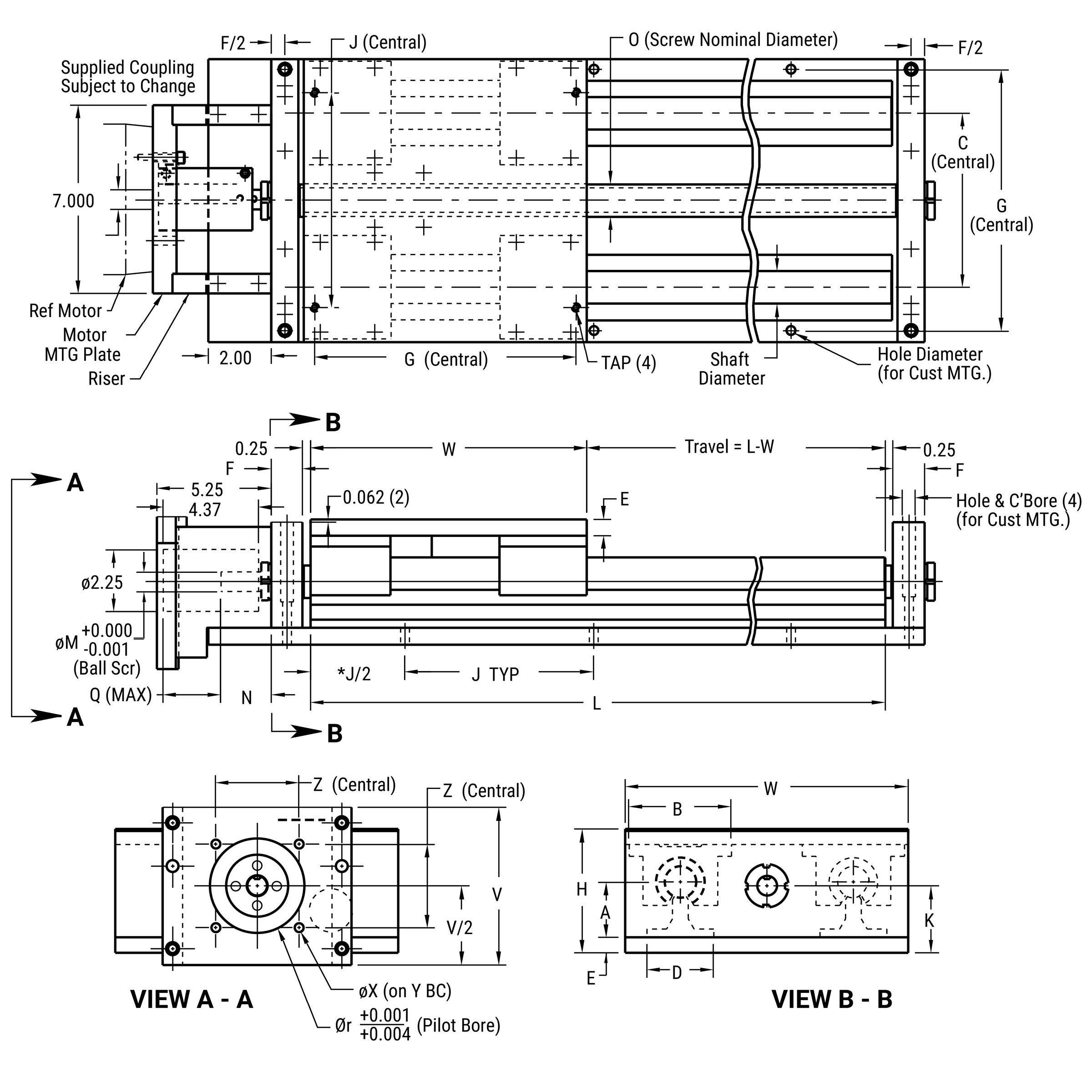
*Hole distance to each end is equal unless specified at time of order
Slide Assembly & NEMA Drive Kit 2N43 & 2N34
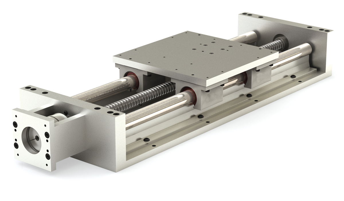
Ordering Example:
To order a slide with a 0.625" diameter alloy steel linear shaft, 28" rail length, 0.200" right hand select ball screw, and a NEMA 23 motor with a 0.250" shaft – specify part number, 2N23A-1000-028.000-AA7R.
Part Number
| Series | Motor Mount | Bearing Type | Internal Lubrication | Size | Shafting Material | Length | Lead | |||
| 2N | XX | X | XXX | - | 08 | XX | - | XXX.XXX | - | YYYY |
Motor Mounting DimensionsSee Motor Mounting Dimensions Table Below Bearing TypeBLANK = Simplicity FrelonGOLD E = Simplicity Frelon® J B = Ball Bearing Internal LubricationBLANK = None (Standard) JKM = Thru hole and internal felt wick Size08 10 12 16 20 Shaft diameter dimension in 1/16" increments Shafting material00 = Alloy Steel (Standard) CC = Ceramic Coated S3 = 303 Stainless Steel SS = 440 Stainless Steel Note: Ball bearings not suitable with ceramic coated shafting. Rail LengthEnter rail length in inches XXX.XXX (EX: 28" = 028.000) LeadSubstitute standard or select lead code from table for “YYYY” |
Standard Lead Table
Accurate to less than 0.007" per foot accumulative
| Size | Available Lead Codes | |||||
|---|---|---|---|---|---|---|
| 08 | AAXR | AAXL | ||||
| 10 | AAXR | AAXL | ||||
| 12 | AAXR | AAXL | ||||
| 16 | ABXR | ABXL | ACXR | ADXR | ||
| 20 | ABXR | ABXL | ACXR | ADXR | ||
AAXR = 0.20 Right Hand
AAXL = 0.20 Left Hand
ABXR = 0.25 Right Hand
ABXL = 0.25 Left Hand
ACXR = 0.50 Right Hand
ADXR = 1.00 Right Hand
Note: Additional leads available upon request.
Select Lead Table
Accurate to less than 0.003" per foot accumulative
| Size | Available Lead Codes | ||||||
|---|---|---|---|---|---|---|---|
| 08 | AAX7R | AA7L | |||||
| 10 | AA7R | AA7L | |||||
| 12 | AA7R | AA7L | |||||
| 16 | AB7R | AB7L | AC7R | AD7R | |||
| 20 | AB7R | AB7L | AC7R | AD7R | |||
AA7R = 0.20 Right Hand
AA7L = 0.20 Left Hand
AB7R = 0.25 Right Hand
AB7L = 0.25 Left Hand
AC7R = 0.50 Right Hand
AD7R = 1.00 Right Hand
Note: Additional leads available upon request.
Motor Mounting Dimensions
Coupling MAX* Torque Dynamic Capacity = 50 in.-lb.
| Size | Drive | R | S | V | X | Y | Z |
|---|---|---|---|---|---|---|---|
| 23A | NEMA 23 | 1.502 | 0.250 | 2.500 | 10-32 | 2.625 | 1.856 |
| 23B | NEMA 23 | 1.502 | 0.375 | 2.500 | 10-32 | 2.625 | 1.856 |
| 34A | NEMA 34 | 2.875 | 0.375 | 3.500 | 10-32 | 3.875 | 2.740 |
| 34B | NEMA 34 | 2.875 | 0.500 | 3.500 | 10-32 | 3.875 | 2.740 |
Note: Contact factory for international drives and low profile slide assembly availability.
*Due to ball screw and nut life/torque capacities for 08, 10, or 12 size slides, do not exceed 30 in.-lb. of input torque without consulting factory
Standard Length Table
| Size | Available Rail Lengths - L* (in inches) | |||||||||||||||||||||||||||||
|---|---|---|---|---|---|---|---|---|---|---|---|---|---|---|---|---|---|---|---|---|---|---|---|---|---|---|---|---|---|---|
| 08 | 008 | 012 | 016 | 020 | 024 | 028 | 032 | 036 | 040 | 044 | 048 | 052 | 056 | 060 | 064 | 068 | 072 | 076 | 080 | 084 | 088 | 092 | 096 | |||||||
| 10 | 008 | 012 | 016 | 020 | 024 | 028 | 032 | 036 | 040 | 044 | 048 | 052 | 056 | 060 | 064 | 068 | 072 | 076 | 080 | 084 | 088 | 092 | 096 | |||||||
| 12 | 012 | 018 | 024 | 030 | 036 | 042 | 048 | 054 | 060 | 066 | 072 | 078 | 084 | 090 | 096 | |||||||||||||||
| 16 | 012 | 018 | 024 | 030 | 036 | 042 | 048 | 054 | 060 | 066 | 072 | 078 | 084 | 090 | 096 | |||||||||||||||
| 20 | 012 | 018 | 024 | 030 | 036 | 042 | 048 | 054 | 060 | 066 | 072 | 078 | 084 | 090 | 096 | |||||||||||||||
*Contact factory for longer or non-standard lengths.
Dimensional Information
| Series | Size | Linear Shaft. Dia |
W | H | A | B | C | D | E | F | G | J | K | M | N | O | Q | Tap | Hole Dia. |
|---|---|---|---|---|---|---|---|---|---|---|---|---|---|---|---|---|---|---|---|
| 2NXX | 08 | 0.500 | 6.00 | 2.562 | 1.125 | 2.00 | 3.50 | 1.500 | 0.375 | 0.75 | 5.500 | 4.00 | 1.375 | 0.375 | 1.45 | 0.631 | 1.31 | 10-24 | 0.22 |
| 2NXX | 10 | 0.625 | 7.00 | 2.750 | 1.125 | 2.50 | 4.00 | 1.625 | 0.375 | 0.75 | 6.312 | 4.00 | 1.375 | 0.375 | 1.45 | 0.631 | 1.31 | 1/4-20 | 0.28 |
| 2NXX | 12 | 0.750 | 8.00 | 3.438 | 1.500 | 2.75 | 4.50 | 1.750 | 0.500 | 1.00 | 7.125 | 6.00 | 1.500 | 0.375 | 1.45 | 0.631 | 1.31 | 1/4-20 | 0.28 |
| 2NXX | 16 | 1.000 | 9.00 | 3.938 | 1.750 | 3.25 | 5.50 | 2.125 | 0.500 | 1.00 | 8.312 | 6.00 | 2.125 | 0.625 | 1.76 | 1.000 | 1.19 | 1/4-20 | 0.28 |
| 2NXX | 20 | 1.250 | 11.00 | 5.125 | 2.125 | 4.00 | 6.50 | 2.500 | 0.750 | 1.25 | 10.000 | 6.00 | 2.375 | 0.625 | 1.76 | 1.000 | 1.19 | 5/16-18 | 0.34 |
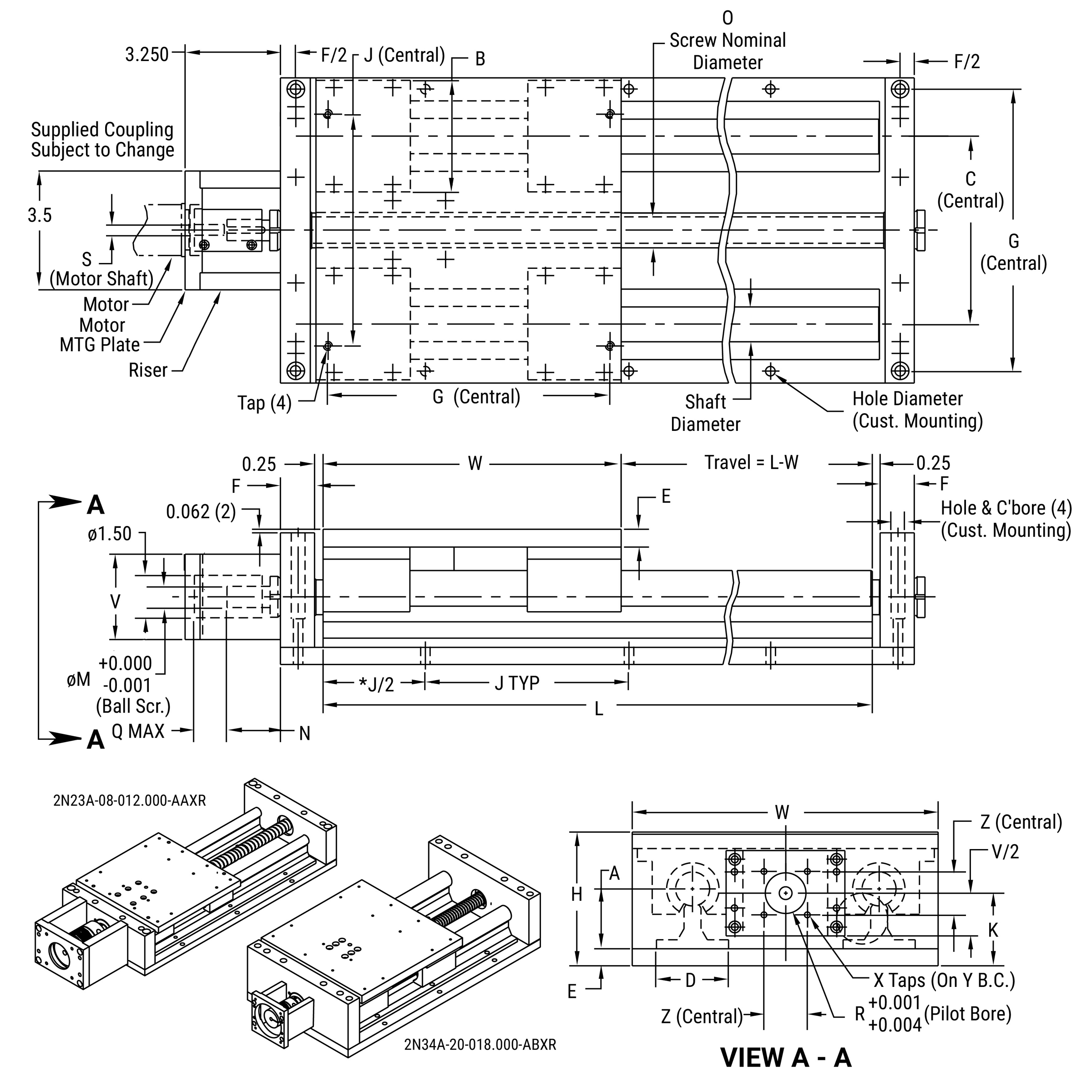
*Hole distance to each end is equal unless specified at time of order
Simplicity Linear Slides
Slide Selection Information
- Determine the size and stroke of slide
- Is a lube system required?
- Please furnish the following to the factory:
- Model designation
- Lube system requirements
- Mounting orientation, saddle position if mounted at an angle
- Load to be carried and approximate center of gravity from saddle center
- Location and magnitude of any force which resists the motion of the slide
- Acceleration rate and maximum velocity of the saddle
- Deceleration rate
- Service life requirements
- Type of environment the slide will operate in
Model Number
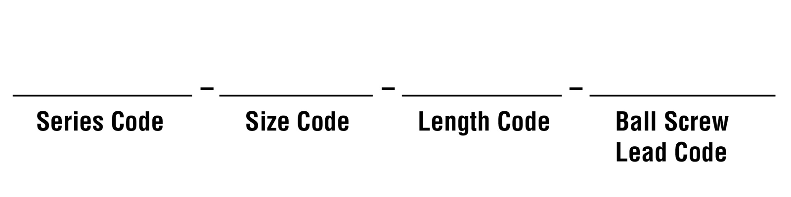
Mounting Orientation
Please indicate the parameters of your application in the boxes below:
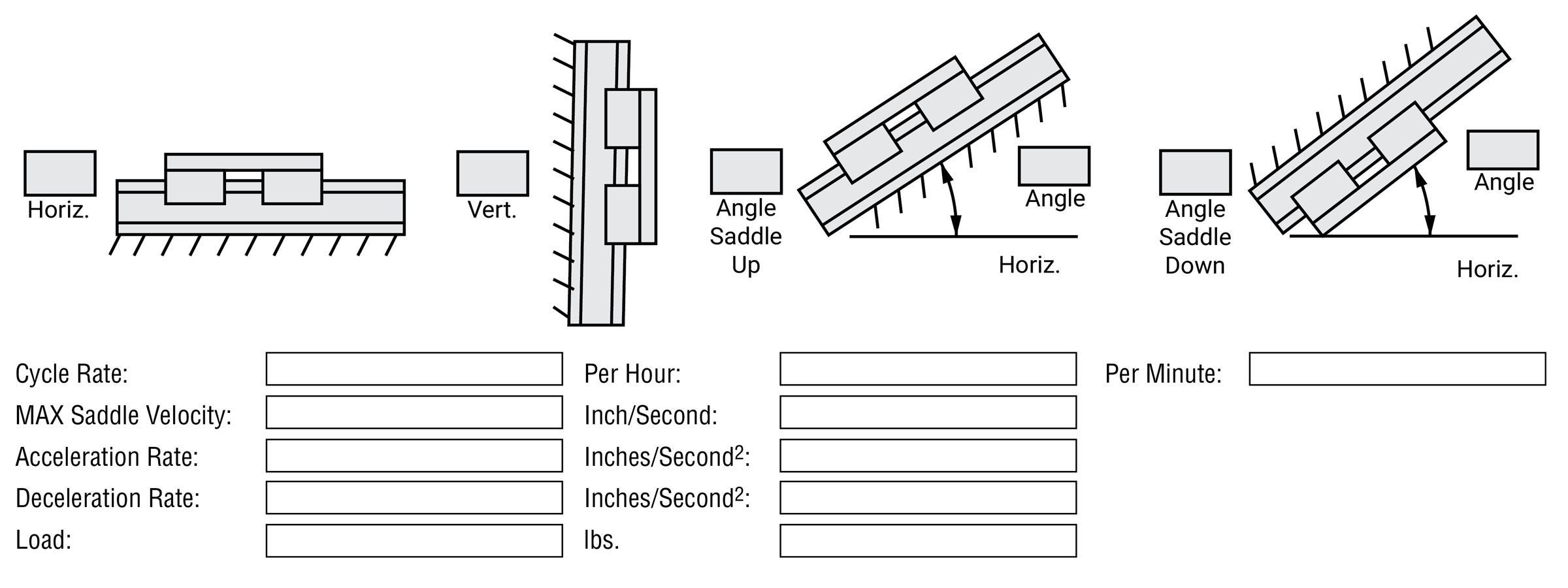
Location of Center of Gravity from Saddle Center
Please indicate the parameters of your application in the boxes below:
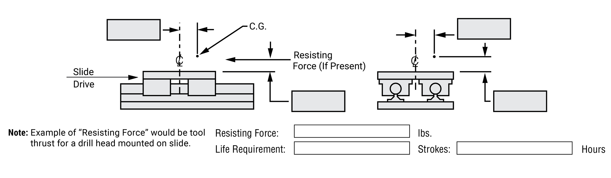
Simplicity Linear Slides Load Capacities
The safe loading recommendations shown apply to plain bearing, non-lubricated slide applications. All slides are to be fully supported and rigidly mounted. Load capacities shown reflect the use of Simplicity linear plain bearings. Contact PBC Linear for load capacities for linear slides with ball bearings.
Standard Mounting
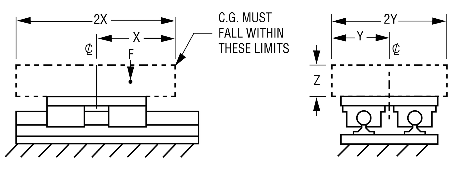
Recommended Safe Loading
| Size | F MAX lb. |
F MAX N |
X in. |
Y in. |
Z in. |
|---|---|---|---|---|---|
| 08 | 1450 | 6450 | 4.00 | 2.37 | 3.00 |
| 10 | 2200 | 9786 | 4.75 | 2.76 | 3.50 |
| 12 | 2850 | 12677 | 5.00 | 2.85 | 4.00 |
| 16 | 5275 | 23464 | 5.50 | 3.37 | 4.50 |
| 20 | 7750 | 34473 | 6.75 | 4.05 | 5.50 |
| 24 | 10600 | 47151 | 7.86 | 4.90 | 6.50 |
| 32 | 18750 | 83400 | 10.75 | 6.00 | 9.00 |
Note: Load ratings apply to Simplicity plain bearings only.
Side Mounting
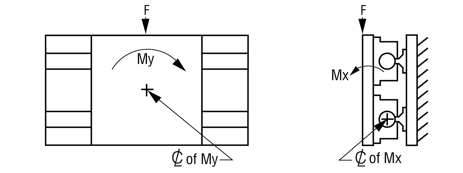
Recommended Safe Loading
| Size | F MAX lb. |
My in.-lb. |
Mx in.-lb. |
F MAX N |
My nm |
Mx nm |
|---|---|---|---|---|---|---|
| 08 | 540 | 910 | 1500 | 2402 | 103 | 169 |
| 10 | 760 | 1680 | 2750 | 3381 | 190 | 311 |
| 12 | 840 | 1710 | 2875 | 3737 | 193 | 325 |
| 16 | 1050 | 3300 | 4430 | 4671 | 373 | 501 |
| 20 | 1750 | 6175 | 8750 | 7784 | 698 | 989 |
| 24 | 2100 | 9600 | 12600 | 9341 | 1085 | 1424 |
| 32 | 3300 | 19000 | 28050 | 14679 | 2147 | 3169 |
Note: Load ratings apply to Simplicity plain bearings only.
Inverted Mounting
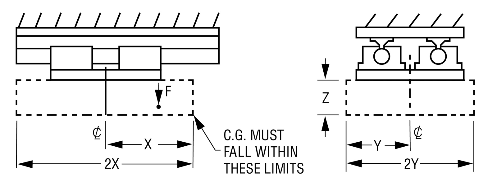
Recommended Safe Loading
| Size | F MAX lb. |
F MAX N |
X in. |
Y in. |
Z in. |
|---|---|---|---|---|---|
| 08 | 195 | 867 | 4.85 | 2.91 | 3.00 |
| 10 | 285 | 1268 | 5.69 | 3.33 | 3.50 |
| 12 | 315 | 1401 | 6.52 | 3.75 | 4.00 |
| 16 | 450 | 2002 | 7.31 | 4.58 | 4.50 |
| 20 | 712 | 3167 | 8.84 | 5.42 | 5.50 |
| 24 | 900 | 4003 | 10.50 | 6.67 | 6.50 |
| 32 | 1425 | 6339 | 14.67 | 8.33 | 9.00 |
Note: Load ratings apply to Simplicity plain bearings only.
Vertical Mounting
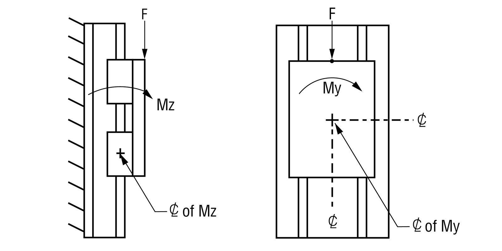
Recommended Safe Loading
| Size | F MAX1,2 lb. |
My in.-lb. |
Mx in.-lb. |
F MAX N |
My nm |
Mx nm |
|---|---|---|---|---|---|---|
| 08 | 260 | 1445 | 1500 | 1157 | 163 | 169 |
| 10 | 300 | 2750 | 2750 | 1334 | 311 | 311 |
| 12 | 300 | 2875 | 2875 | 1334 | 325 | 325 |
| 16 | 600 | 5000 | 4430 | 2669 | 565 | 501 |
| 20 | 675 | 9500 | 8750 | 3003 | 1073 | 989 |
| 24 | 710 | 14400 | 12600 | 3158 | 1627 | 1424 |
| 32 | 900 | 32300 | 28050 | 4003 | 3649 | 3169 |
Note: Load ratings apply to Simplicity plain bearings only. 1 Applies only when using 2RPS and 2LRPS slides. 2 If “F” is exceeded consult factory. For RPS, FMAX is dependent upon customer’s method of moving the slide.
Simplicity Linear Slides
Column Load Chart
Compression (Column) Load
Compression-column load is a load that tends to buckle or compress the screw shaft.
How To Use Chart:
- Determine maximum compression load (lb.)
- Determine slide length. (“L” dimension)
- Determine end fixity and slide designation (2RPS and 2LRPS)
- Find the point at which load and length intersect
- Select a slide above or to the right of the intersecting point
Note: Applies primarily to vertical applications.
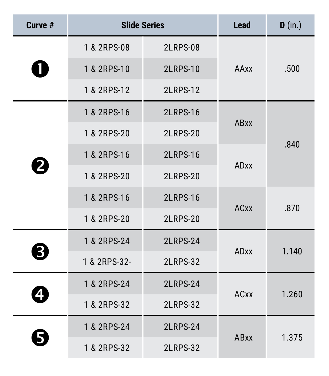
Column Load Formulas:
\( P_C = C_C \cdot 14.03 \times 10^6 \cdot \left( \frac{D^4}{L^2} \right) \)
\( P_C \) = Critical column load (lb.)
\( D \) = Root diameter of screw (in.) (See chart)
\( L \) = Slide length (in.)
\( C_C \) = End fixity factor
\( C_C \) = 0.25 for 1RPS
\( C_C \) = 2.0 for 2RPS and 2LRPS
Note: Chart figures at 80% of actual load. Do not exceed these figures.
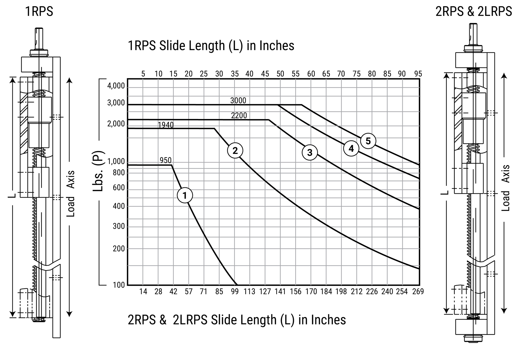
Simplicity Linear Slides
Critical Speed Chart
Critical Speed
The maximum speed at which a ball screw or ball nut can rotate without producing destructive resonant vibrations. The critical speed is a function of the ball screw diameter, the unsupported length of the screw, rigidity of the bearing supports, and RPM.
How To Use Chart:
- Determine end fixity. How many ends are fixed? (Slide designation, 2RPS and 2LRPS)
- Determine slide length. (“L” dimension)
- Find the length – fixity vertical line, read up to find the intersecting, at the required travel rate
- Select a slide above or to the right of the intersection point
- Higher speeds and/or longer lengths are available as cost effective specials, having a larger ball screw and bearings
Note: Applies primarily to vertical applications.
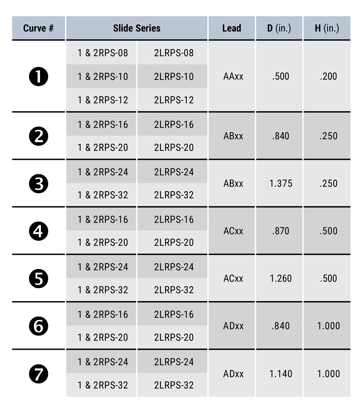
Critical Speed Formulas:
\( N = C_S \cdot 7.93 \times 10^4 \cdot \left( \frac{DH}{L^2} \right) \)
\( N \) = Critical speed (MAX) (expressed in in./sec.)
\( D \) = Root diameter of screw (See chart)
\( H \) =Lead of screw (in.) (See chart)
\( L \) = Slide length (in.)
\( C_S \) = End fixity factor
\( C_S \) = 0.36 for 1RPS
\( C_S \) = 1.47 for 2RPS and 2LRPS
Note: Chart figures at 80% of actual load. Do not exceed these figures.
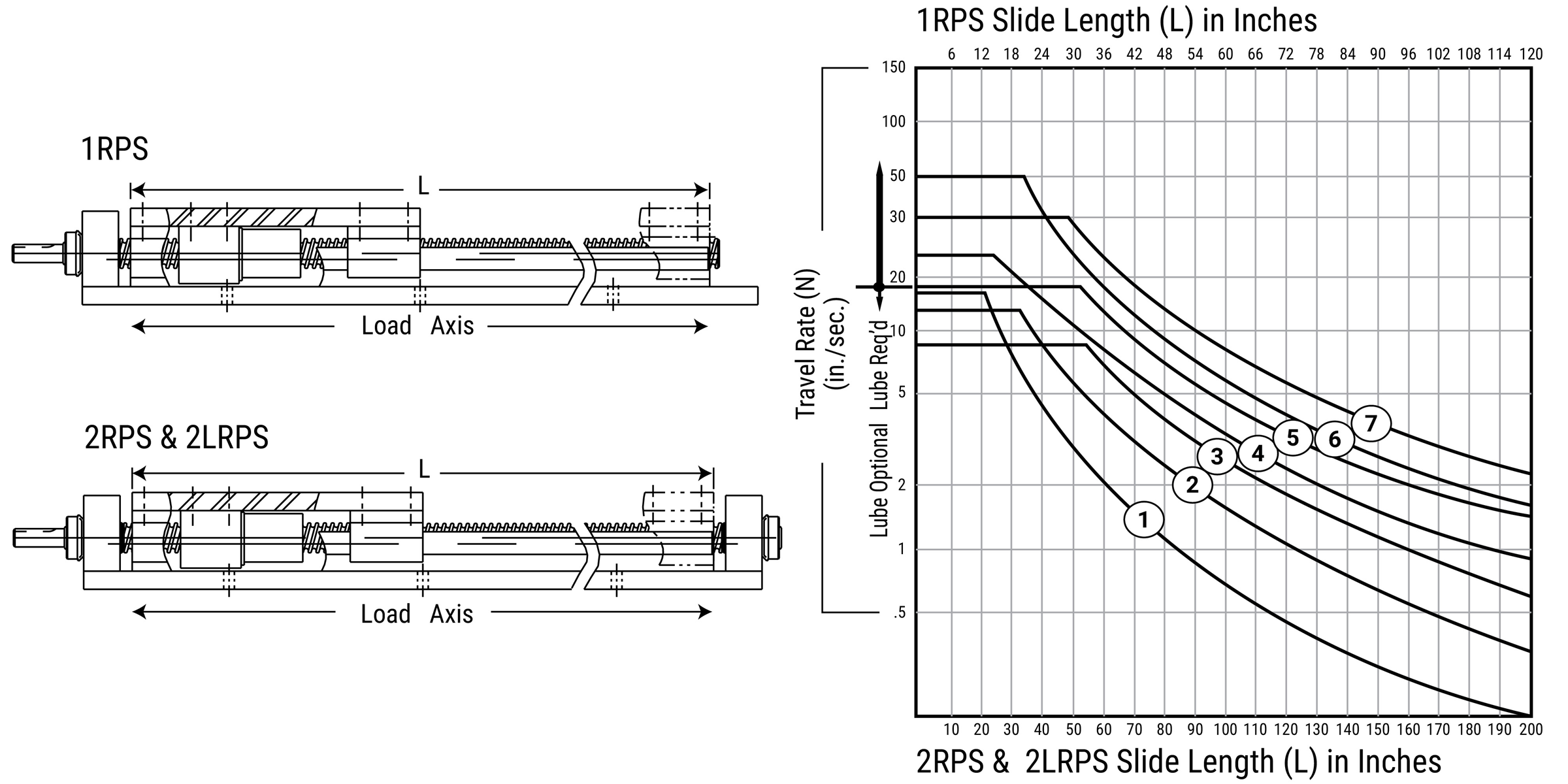
Simplicity Plain Bearings Ratings
Classes of Plain Bearings
Simplicity bearings are in a class of bearings known as Plain bearings, which means that they have no rolling elements. There are three classes of Plain bearings:
Class I – Require an outside source of lubrication (oil, grease, etc.).
Class II – Lubrication is impregnated within the walls of the bearing. (Bronze, powder metal, etc.) Typically, these bearings require an added lubricant also.
Class III – Self-lubricating bearings, which do not require added lubricants.
Simplicity bearings are Class III Plain bearings and are self-lubricating.
Rating a Plain Bearing
Plain bearing performance capacity is rated by PV.
P = Pressure or load in pounds per square inch (psi) or kilograms per square centimeter (kg/cm2).
V = Velocity or surface speed in feet per minute (fpm or sfm) or meters per minute (m/min.).
PV = Pressure velocity value (Pressure x Velocity)
Simplicity Maximum Parameters
| Maximum Parameters | P | V Running Dry |
PV |
|---|---|---|---|
| Frelon® J | 1500 psi or 105.45 kgf/cm | 140 sfm or 42.67 m/min. | 10,000 psi x ft./min. or 215 kgf/cm2 x m/min. |
| FrelonGOLD® | 3000 psi or 210.9 kgf/cm2 | 300 sfm or 91.44 m/min. | 20,000 psi x ft./min. or 430 kgf/cm2 x m/min |
Note: All three parameters must be met by an application for the bearing to perform properly.
Formulas for Ratings
Pressure is over the projected area of load:
\( A = L \cdot d \)
\( P = \frac{W \, \text{psi}}{A} \) (or \( \text{kg/cm}^2 \))
Velocity:
Linear = total distance traveled in one minute
Rotational Velocity:
\( V = \frac{\pi \cdot d \cdot n \, \text{fpm}}{12} (\text{or m/min.}) \)
Pressure Velocity Value (PV):
\( PV = P \cdot V \, \text{psi} \cdot \text{fpm} \) (or \( \text{kg/cm}^2 \cdot \text{m/min.} \))
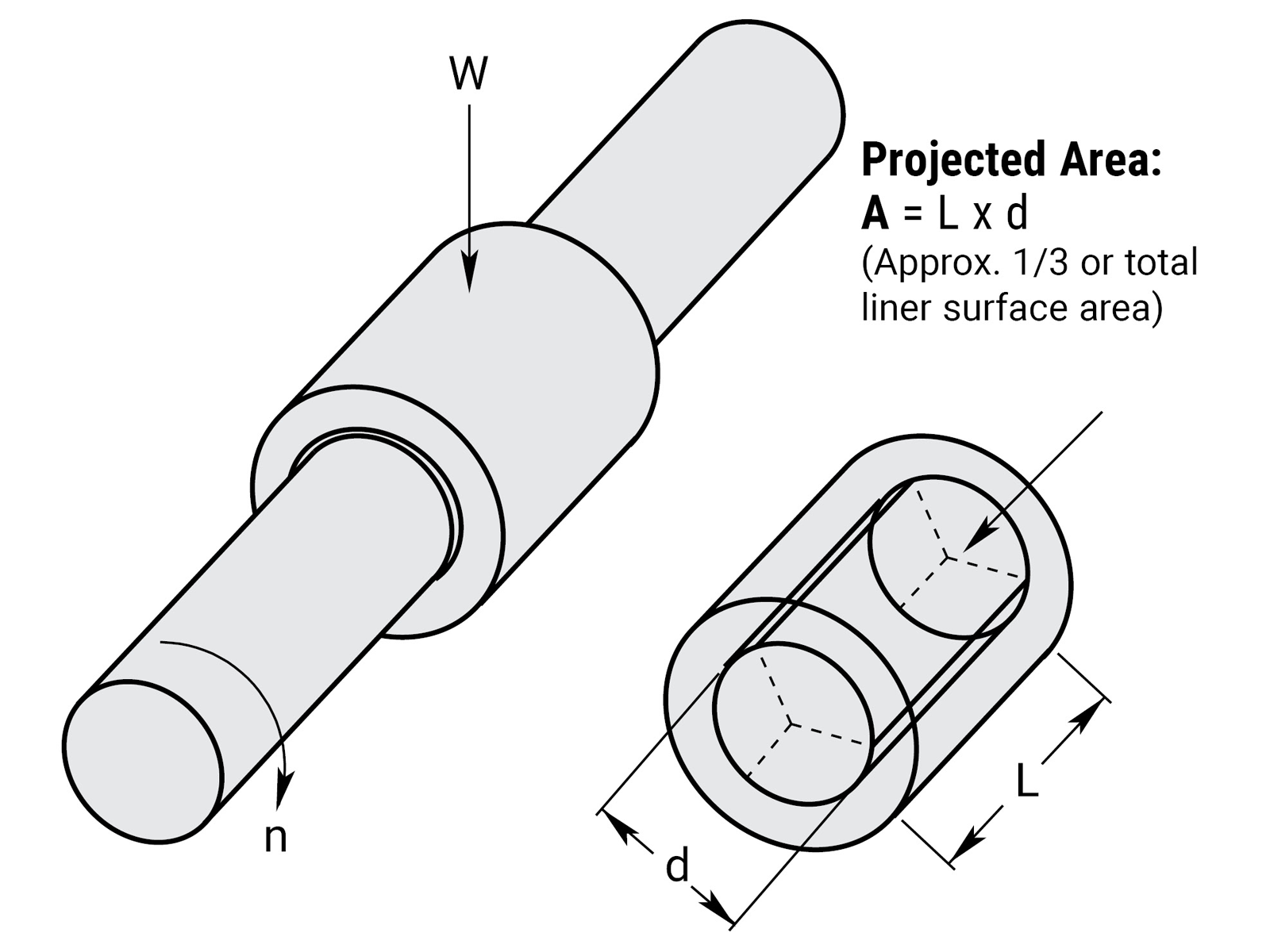
W = MAX Load
L = bearing length
d = shaft diameter
A = projected contact area
n = rotational speed (rpm)
PV equivalents
| Inch | Technical Metric | Int'l Metric (SI) | |
|---|---|---|---|
| Load | 1 psi | .0703 kgf/cm2 | .0069 N/mm2 |
| Velocity | 1 ft./min. | .3048 m/min. | .00508 m/sec. |
| PV | 1 PV | .0214 PV | .000036 PV |
| FrelonGOLD Max PV | 20,000 | 430 | 0.72 |
| Frelon J Max PV | 10,000 | 215 | 0.36 |
Simplicity Plain Bearings
Types & Effects of Lubrication
Types and Effects of Lubrication
Lubrication is any outside technique used for reducing the friction, wear, or both of a bearing. Proper lubrication of Simplicity bearings is critical. Evaluate lubrication needs on an application-by-application basis to determine whether or not it should be used at all, what type is needed, and how it is applied. Below are some criteria on which to base the lubricant decision:
Do not use WD40™, PTFE sprays, or other oils, greases, or sprays that contain fluorocarbons or silicone. In testing, these lubricants have proven to cause long-term stick-slip problems with the Frelon lined bearings. They tend to become a gummy substance that ultimately increases friction.
Recommended Lubricants:
- Waylube oils
- Lightweight oils
- 3-in-1 type oils
- Lightweight petroleum based greases
Using Oils with Simplicity
DO NOT USE ANY TYPE OF MOTOR OIL OR OILS WITH ADDITIVES!
These types of oils work well short term, but quickly become ineffective, and will cause stick-slip reactions in the bearing. As a rule of thumb, the less additives in the oil, the better the performance. Recommended oils are Mobil Vactra #2 (a way lube oil) and any standard 3-in-1 oil. The 3-in-1 oils are tremendous cleaning oils and are the best in preparing for a proper transfer of PTFE to the shafting.
Grease Products
DO NOT USE A MOLY FILLED OR OTHER TYPE FILLED GREASES!
They become like a lapping compound on the ID of the bearing and increase wear dramatically.
Proper Use of Greases
Proper use of grease is critical for trouble-free operation.
Be sure the felt wick is removed from a “FL-xx-JKM” bearing because grease inserted through the zerk will cause the wick to act like a brake.
Do not fill all of the running clearance with grease! The temptation is to treat it like a rolling element bearing and fill it until it weeps from the end. This will cause greater friction and binding.
The rule of thumb for the bearing liner that “thin is better” applies to the use of grease also.
If grease is used and does not work in the application, it is possible to salvage the bearing with minimal work and to continue to operate. Follow the steps below:
- If possible, remove the bearing from the housing, wipe the grease from the liner, use a 3-in-1 type oil to clean the excess remaining grease, and reinstall.
- If it is not possible to remove the bearing, wipe as much grease as possible away from the ends of the bearing, then start to fill with a 3-in-1 type oil for cleaning the liner. To speed the cleaning process, apply forced air to the bearing through the zerk hole and continue using oil lubrication.
Effects of Lubrication
Lubrication can greatly increase the performance of a bearing when applied properly as noted earlier. Actual performance results for specific applications are difficult to predict due to the number of elements involved (temperature change with lube, useable life, or aging of lubricant, etc.). Specific application testing is recommended to establish specific performance parameters.
Simplicity Plain Bearings Load Capacity
Load Capacity (Pressure)
Depending upon the material used, a plain bearing’s load capacity can greatly exceed a rolling element bearing. There are three basic reasons for this:
- The area of surface contact with the shaft is far greater than rolling element bearings, which have point-to-point contact with a given number of balls.
- A rolling element bearing must be oriented properly for the ball tracks to carry the load adequately, while a Plain bearing can be mounted in any orientation.
- Only one or two of the tracks in a rolling element bearing will actually carry any of the load applied.
Simplicity bearings have a thin liner that is bonded to a metal shell at the molecular level, allowing the load to be transferred throughout the bearing. This gives it an advantage over other Plain bearings of solid plastic or polymer materials. These other materials will tend to “cold flow” under pressure. “Cold flow” means to deform or lose shape. The idea is similar to pressing your finger into a bar of soap – material will move or deform as pressure is applied.
Linear Surface Speeds (Velocity)
In typical applications, speed is a known quantity and easily converted. Typically feet per minute or meters per minute are used. The most important factor that speed (along with friction) produces is heat buildup. This is not a critical factor in most linear applications because the heat is dissipated over the length of travel, and it does not affect the bearing. Short stroke or extremely high speed applications may see the effects of heat buildup in thermal expansion and the bearing ID locking on the shaft. A compensated ID bearing (FLC) is recommended in these applications.
Factors that Contribute to Wear Life
Plain bearings are rated by the wear rate of the bearing material. Wear is greatly dependent upon the proper application of the bearing and material used.
- Proper mating of shaft and liner materials.
- Surface finish 8-16 Ra (.20-.40 mm) is required. Peaks in the surface that are polished to a radius provide the best running surface. Sharp peaks in the finish will be like a fine lapping compound wearing the I.D. of the bearing.
Note: Shafting damaged by use with ball bearings can be salvaged and used with Simplicity bearings. Spin in a lathe and polish with sand papers in this order: 120 grit, 180 grit, and 300 grit. This will also remove sharp peaks in the surface finish.
- Surface speed - at high speeds, heat buildup will affect liner wear.
- Break-in transfer - proper transfer process of the liner to the shaft.
- Lubrication - proper lubrication can greatly improve the wear rate of a bearing. At the same time, improper lubrication can increase wear and failure.
- Load & Wear Relationship - wear rate is proportional to load to the third power: wear rate x load³.
If load is reduced to 1/2, wear will be reduced to (1/2)³
- Contamination - while migrating into the bearing and embedding into the liner, certain types of contamination may, over time, cause increased wear to the liner.
Note: This is not an all inclusive list. There are many more factors within an application that can affect wear to different degrees. These are the major issues and the first things to address in a design.
Simplicity Plain Bearings Wear Rate
Wear Rate vs. Life Expectancy
A rolling element linear bearing’s life expectancy is usually expressed in total inches or meters. A rolling element rotary bearing’s life expectancy is expressed in hours of operation. Both are also rated for average (L-50) and minimum (L-10) life. L-50 life is the average life that can be expected from 50% of rolling element bearings. In other words, 50% will not reach the average life expectancy. L-10 life is the minimum life (1/5 the average life) expected from 90% of rolling element bearings. In other words, 10% will not reach the minimum life expectancy. Theoretically they could fail upon installation.
Plain bearings are not rated by a life expectancy but by the wear rate of the bearing material. Wear is greatly dependent upon the proper application of the bearing and material used. If it is not properly applied, it will fail. Failure, however, is subjective and dependent upon specific application requirements. 0.002" running clearance may not be acceptable in one application while another may be able to run a bearing until the liner is completely worn through. The user may then rotate it 30 degrees and continue to run it. This broad range of acceptability makes it difficult to determine life expectancy.
The first step is to determine what wear is acceptable for your application. Then utilizing the test data below, you can estimate the wear expected for your given application.
Wear Test Sample
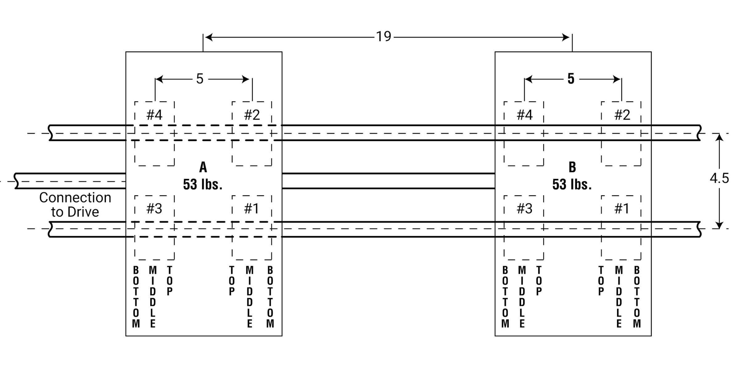
Conducted by: Pacific Bearing® Company
Bearing Material: FrelonGOLD®
Shaft Material: Standard RC60 steel shafting
Surface Finish: 8-12 Ra
Speed: 140 fpm (70 cycles/min.; 1,680"/min.; 100,800"/hour; 2,419,200"/day)
Stroke: 12"
Load: 10.87 psi (53 lb.)
Bearings Used: FLN12 (3/4" open style bearings)
Lubrication: None
Total Wear to Bearing Material: FrelonGOLD = 0.00042"
Note: Wear is an average of totals taken from 4 bearings per carriage.
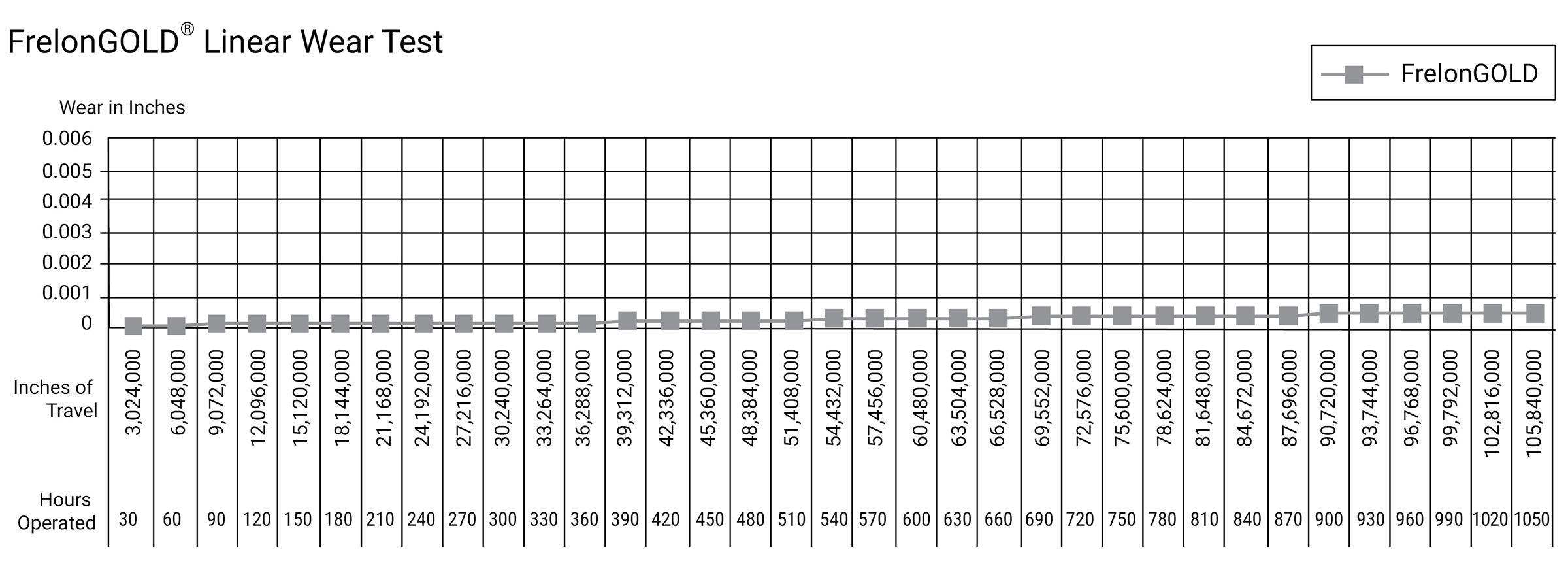
Simplicity Plain Bearings Coefficient
of Friction
Coefficient of Friction
A frequent misconception of Plain bearings is that wear and friction are basically synonymous, in that, high friction equals high wear or that low friction equals low wear. While there can be a relation between the two, they should be addressed as separate issues in the design process.
For example, dry running virgin (unfilled) PTFE on steel’s coefficient of friction (c.o.f.) is approximately 0.1 while filled PTFE’s c.o.f. can range from 0.125 to 0.4 depending on the fillers used. By comparison, however, the virgin PTFE will wear at a much greater rate.
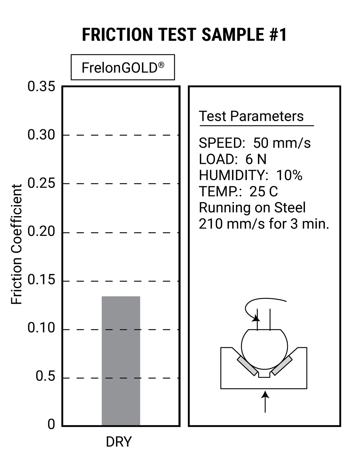
Conducted by: Dr. Tillwich GmbH
Managing Director: Mr. Werner Stehr (World leading tribologist with a seat on the ISOTC123 Committee establishing standards for tribological testing)
Bearing Material: FrelonGOLD®
Shaft Material: Standard RC60 steel shafting
Surface Finish: 8-12 Ra
Speed: 50 mm/sec.
Load: 6 N
Temperature: 25° C
Lubrication: None
Average Coefficient of Friction: FrelonGOLD = 0.125
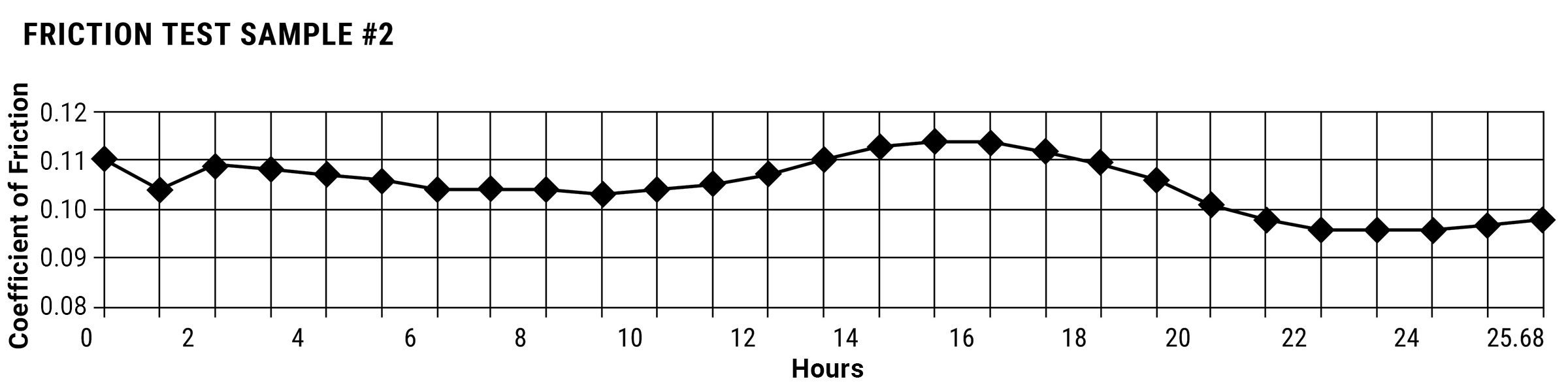
Conducted by: FrelonGOLD material processor
Bearing Material: FrelonGOLD®
Shaft Material: CRS 1018
Surface Finish: 8 Ra
Speed: 100 fpm
Duration: 25.68 hours
Load: 100 psi
Lubrication: None
Average COF: 0.10
Max. COF: 0.15
Min. COF: 0.08
Average Running Temperature: 95.4° F
Simplicity Plain Bearings
Cantilevered Loads
Cantilevered Loads
- Maximum 2:1 ratio
- 1x = bearing separation on same shaft
- 2x = distance from shaft to load or force
Example: If 2x equals 10” then 1x must be at least 5”
This principle is NOT load dependent. It is NOT due to edge loading. It is also NOT dependent on the driving force used. The bearings will bind whether hand or mechanically driven. This principle is a product of friction.
⚠ CAUTION
Binding will occur if the 2:1 ratio is exceeded!
Working through the following equation will explain why this is a product of friction:
P = force being applied
L = distance out from shaft that P is being applied
s = center to center spacing of bearings
f = resultant force on bearings by shaft
F = friction force on each bearing
µ = coefficient of friction (about .25 when not moving)
Balance the moments:
\( f \cdot s = L \cdot P \)
Compute friction force:
\( F = f \cdot \mu\)
Note: Total friction force pushing up is 2 * F. To lock up the slide, the total friction force must be equal to (or greater than) P.
\( P = 2 \cdot F = 2 \cdot f \cdot \mu\)
Substitute for P:
\( \frac{L}{s} = \frac{f}{2 \cdot f \cdot \mu} = \frac{1}{2 \cdot \mu} \Rightarrow \frac{L}{s} = \frac{1}{2 \cdot \mu} \)
Note: The forces drop out of the equation.
Assume static coefficient of friction is .25 (µ = .25) then L / s = 2 That is the 2:1 ratio. There may be other factors that add to the braking effect, but the coefficient of friction is the main cause.
Note: Proper lubrication can help to drop friction and extend the 2:1 ratio.
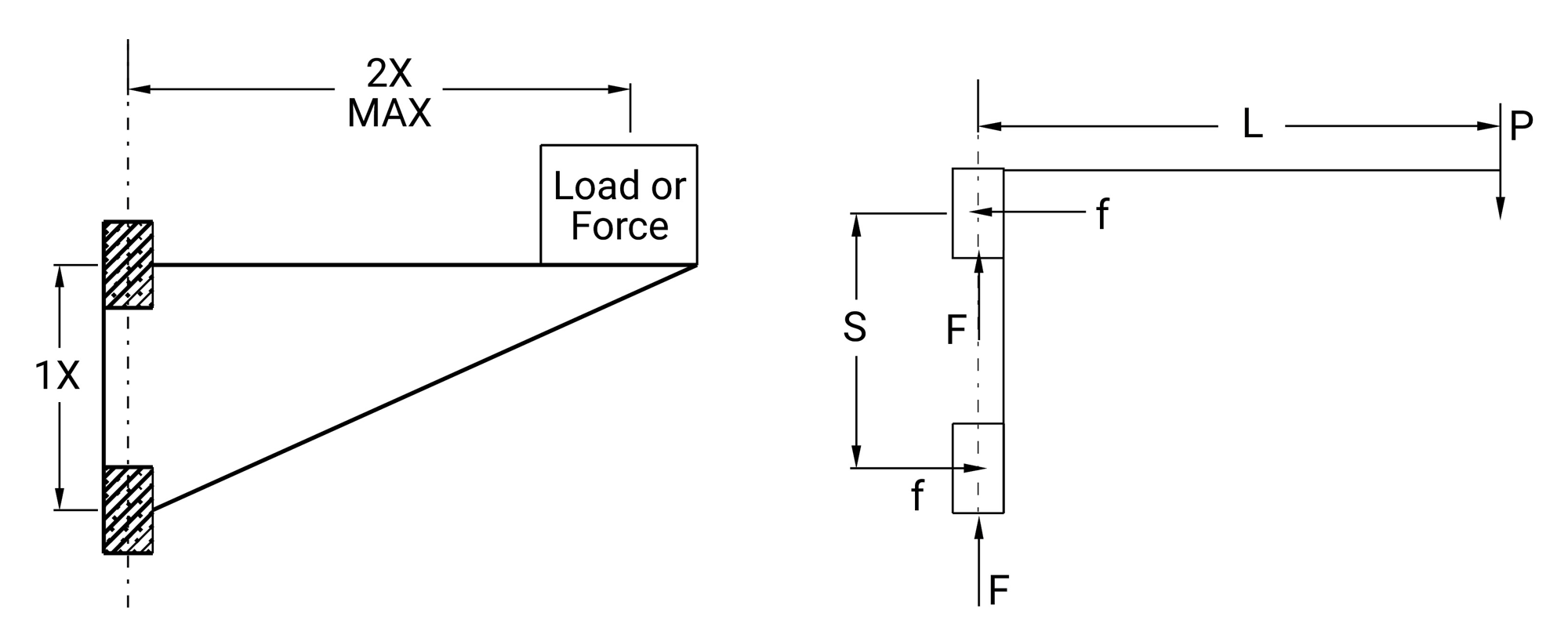
Counterbalance
If holding the 2:1 ratio is not possible, one method of preventing binding problems is using a counter balance.
For efficient counter balances in horizontal applications, use this formula:
\( M \cdot Y = W \cdot Z \)
Note: To avoid problems when running without mass:
(M) Z = 1-1/2 s
W can be calculated. Load on bearing will be:
\( \frac{M + W}{\text{# of bearings}} \)
Example: 50 • 24 = W • Z (Z = 1-1/2 • 6 = 9)
\( W = \frac{50 \cdot 24}{9} = 133lb.\)
Load per bearing:
\( \frac{50 + 133}{4} = 45.75 \text{ lb. / bearing}\)
Cantilever Loads and Drive Force Location without Counterbalance
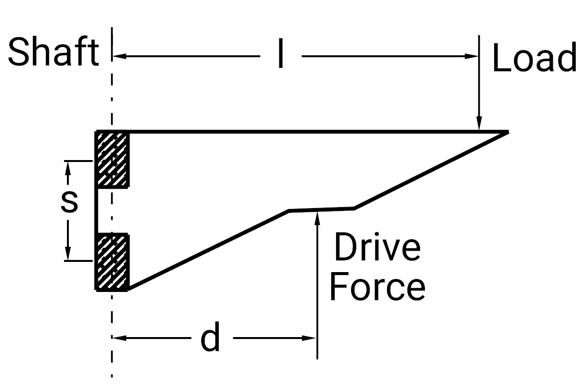
d = distance from shaft to Drive Force
l = distance from shaft to the load center of gravity
s = center-to-center spacing of the bearings on the shaft (If non-self-aligning, then outside to outside distance should be used.)
L = l / s = Load Force Ratio
D = d / s = Drive Force Ratio
Hanging or “Top Heavy” Horizontal Applications with High Acceleration Rates:
If your application will have high acceleration forces, use this formula for the value of the Drive Force Ratio:
\( D = 0.8 \cdot L \times \sqrt{a} \) where a is acceleration in g's.
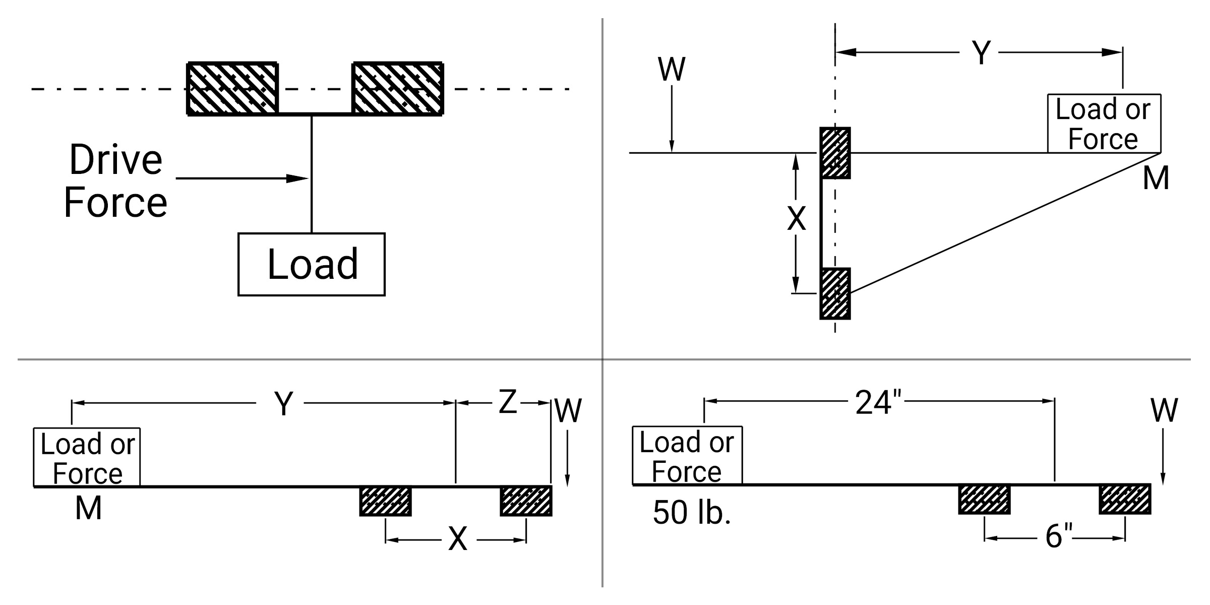
General Rules:
- Drive Force Ratio (D) should never be larger than 2. A Drive Force Ratio (D) larger than 2 can cause the slide to lock up.
- Load Force Ratio (L) can be larger than 2, but as this ratio increases, the drive force required to move the slide increases dramatically. A Load Force Ratio (L) larger than 4 is not recommended.
- If the slide is occasionally operated unloaded, use the distance to the slide’s center of gravity as the distance to the load ( l ).
Vertical Applications:
- If L is between 0 and 2, the lowest drive forces occur when the value of D is about 90% of L (D = 0.9 • L). However, D values between 0 and L will work fine.
- If L is between 2 and 4, use this equation: D = 4 - L
Horizontal Applications:
For best results, the drive force should be applied as close to the shaft as possible no matter what the value of the Load Force Ratio (L) is.
Shaft Deflection
Single Point Shaft Deflection
In applications where a support rail is not used, shaft deflection can become critical in the function of the bearing. If deflection is greater than the misalignment capabilities of a standard pillow block, binding can occur.
One solution would be to increase shaft and bearing size (to lessen the amount of deflection) or to use an open bearing configuration with a support rail.
Follow the formulas below to check shaft deflection and sag.
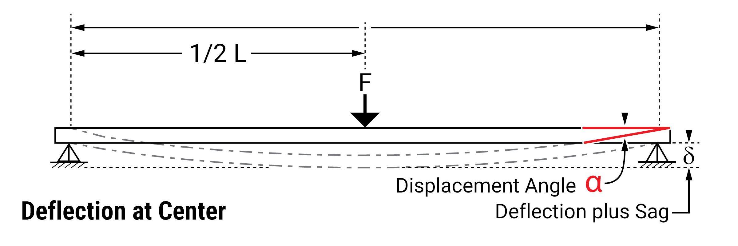
Formula for Inch and Metric Shafting Deflection
Total shaft deflection in horizontal applications:
\( \text{Total Deflection} (\delta) = \text{Def} + \text{Sag} = \frac{F L^3}{48 E I} + \frac{55 L^4}{384 E I} \)
\( \text{Deflection} = w \cdot L^3 / D \)
\( \text{Sag} = L^4 / S \)
\( \text{Deflection} = \text{Pure deflection due to load at center of shaft*} \)
\( \text{Sag} = \text{Deflection of shaft due to its own weight*} \)
\( \text{L} = \text{Shaft unsupported length*} \)
\( \text{F} = \text{load being applied at center of shaft**} \)
\( \text{D} = \text{Deflection coefficient} (D = 48 \cdot E \cdot I) \)
\( \text{S} = \text{Sag coefficient} (S = E \cdot I \cdot 384 / (5 \cdot sw)) \)
\( \text{a} = \text{Displacement angle} \)
\( \text{EI} = \text{(Modulus of Elasticity, E)} \cdot \text{(Second Moment of Area, I)} \)
\( \text{w} = \text{Unit weight of shaft. (lb/in for inch shafts and N/mm for metric shafts)} \)
* inch for inch shafts, mm for metric shafts
** lb for inch shafts, N for metric shafts
Notes:
\(I = \pi \cdot diam^4 / 64 \)
\(sw = \pi \cdot diam^2 / 4 \cdot density \)
\( \text{E} = \text{Modulus of Elasticity (Young’s modulus)} \)
Two Point Shaft Deflection
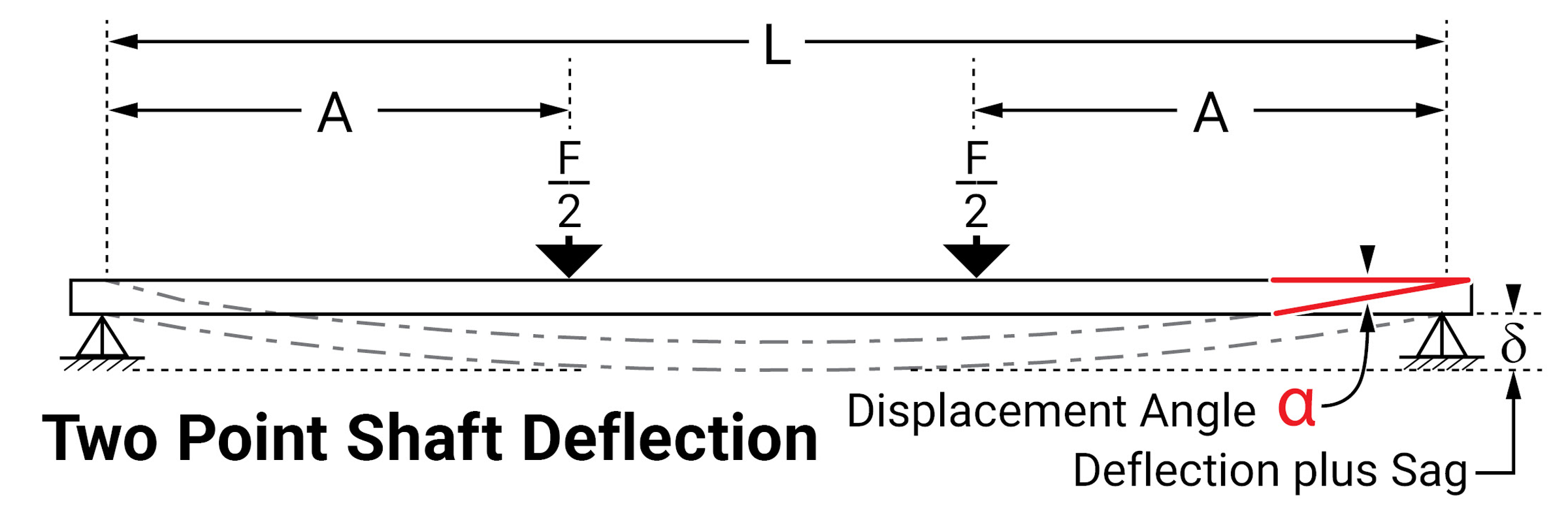
\( \delta = \frac{F A (3 L^2 - 4 A^2)}{48 E I} + \frac{5 w L^4}{384 E I} \)
δ = Total Deflection
L = Distance between the shaft support
E = Modulus of elasticity
I = Shaft moment of inertia
w = Unit weight of shaft; reference the table below
F = Load applied (including carriage weight)
A = Distance to end
a = Displacement angle
Inch Shafting
| Shaft Diameter | Hardened Steel | Stainless Steel | ||
|---|---|---|---|---|
| EI LB·IN.2 |
w LB/IN. |
EI LB·IN.2 |
w LB/IN. |
|
| 3/16" | 1.76E+03 | 0.0077 | 1.76E+03 | 7.70E-03 |
| 1/4" | 5.60E+03 | 0.0138 | 5.59E+03 | 1.37E-02 |
| 3/8" | 2.85E+04 | 0.0311 | 2.84E+04 | 3.10E-02 |
| 1/2" | 9.04E+04 | 0.0553 | 9.01E+04 | 5.51E-02 |
| 5/8" | 2.21E+05 | 0.0865 | 2.20E+05 | 8.62E-02 |
| 3/4" | 4.59E+05 | 0.1250 | 4.57E+05 | 1.24E-01 |
| 7/8" | 8.51E+05 | 0.1700 | – | – |
| 1" | 1.45E+06 | 0.2220 | 1.45E+06 | 2.21E-01 |
| 1-1/8" | 2.33E+06 | 0.2810 | – | – |
| 1-1/4" | 3.55E+06 | 0.3470 | 3.54E+06 | 3.46E-01 |
| 1-3/8" | 5.20E+06 | 0.4200 | – | – |
| 1-1/2" | 7.36E+06 | 0.4990 | 7.33E+06 | 4.98E-01 |
| 1-3/4" | 1.36E+07 | 0.6800 | – | – |
| 2" | 2.33E+07 | 0.8880 | 2.32E+07 | 8.85E-01 |
| 2-1/2" | 5.68E+07 | 1.3900 | – | – |
| 3" | 1.18E+08 | 2.0000 | – | – |
| 4" | 3.72E+08 | 3.5500 | – | – |
Metric Shafting
| Shaft Diameter | Hardened Steel | Stainless Steel | ||
|---|---|---|---|---|
| EI N·mm2 |
w N/mm |
EI N·mm2 |
w N/mm |
|
| 4 mm | 2.54E+06 | 0.00096 | 2.53E+06 | 0.00096 |
| 5 mm | 6.22E+06 | 0.00150 | 6.19E+06 | 0.00150 |
| 6 mm | 1.29E+07 | 0.00217 | 1.29E+07 | 0.00216 |
| 8 mm | 4.10E+07 | 0.00386 | 4.08E+07 | 0.00384 |
| 10 mm | 1.00E+08 | 0.00603 | 9.96E+07 | 0.00601 |
| 12 mm | 2.08E+08 | 0.00869 | 2.07E+08 | 0.00866 |
| 16 mm | 6.57E+08 | 0.01550 | 6.54E+08 | 0.01540 |
| 20 mm | 2.54E+09 | 0.02420 | 1.60E+09 | 0.02410 |
| 25 mm | 3.92E+09 | 0.03780 | 3.90E+09 | 0.03760 |
| 30 mm | 8.14E+09 | 0.05440 | 8.10E+09 | 0.05420 |
| 40 mm | 2.57E+10 | 0.09670 | 2.56E+10 | 0.09640 |
| 50 mm | 6.28E+10 | 0.15100 | 6.25E+10 | 0.15100 |
| 60 mm | 1.30E+11 | 0.21800 | – | – |
| 80 mm | 4.12E+11 | 0.38700 | – | – |
Displacement Angle
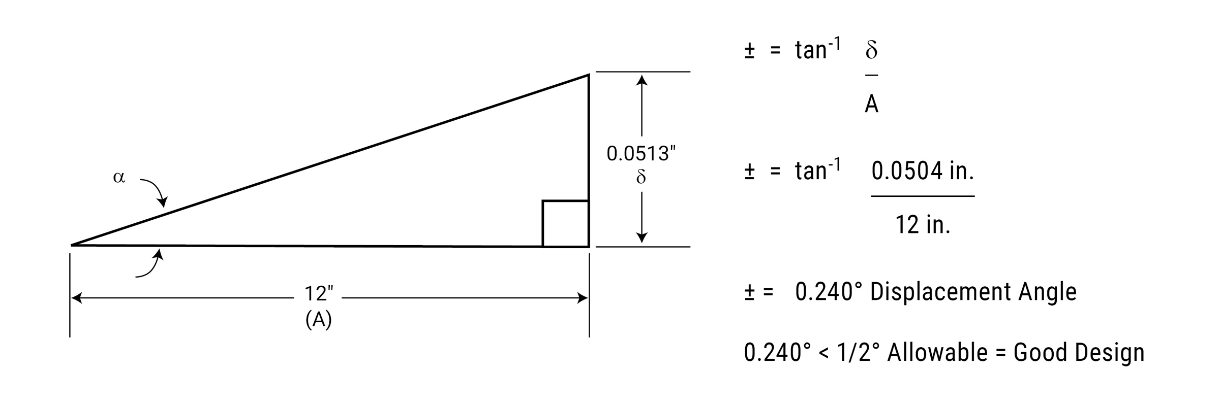
Simplicity Linear Plain Bearings
Installation
Installing Simplicity® Bearings
Applies to standard linear bearing series.
Straight Bore Housing – Press Fit Bearing
This type of configuration is NOT recommended for the vast majority of applications using Simplicity bearings.
It does NOT allow for any misalignment or shaft deflection.
Misalignment or shaft deflection will cause the bearing to bind on the shafting.
Extremely high precision applications may be able to employ this type of mounting. Typically the shafting has been aligned with a laser or some other highly precise equipment.
Due to bore closure in the pressing process, use a “C” series (compensated I.D.) bearing.
Example: FLC24, FMC30, FJC30
The recommended installation procedure is to freeze the bearings at 0°F (-17.75°C) for 30-45 minutes. Using gloves, remove the bearings from the freezer and slip them into the housing. As they heat to room temperature, full contact between bearing and housing will be achieved. The greatest advantage to this technique over traditional pressing is greater accuracy in alignment.
This type of mounting will not allow for misalignment or shaft deflection. Both are very critical in the smooth operation of Simplicity bearings. A rolling element bearing may appear to initially operate in this condition, but it is operating in an extremely preloaded condition and will prematurely fail and in most cases destroy the shafting. Simplicity bearings will indicate the problem immediately upon installation by failing to move due to the binding condition. There are alternative mounting options that work extremely well.
| Part No. | MIN Housing I.D. in. |
MAX Housing I.D. in. |
|---|---|---|
| FLC03 | 0.3729 | 0.3737 |
| FLC04 | 0.4978 | 0.4986 |
| FLC06 | 0.6228 | 0.6236 |
| FLC08 | 0.8725 | 0.8734 |
| FLC10 | 1.1224 | 1.1234 |
| FLC12 | 1.2474 | 1.2484 |
| FLC16 | 1.5596 | 1.5607 |
| FLC20 | 1.9970 | 1.9981 |
| FLC24 | 2.3717 | 2.3729 |
| FLC32 | 2.9965 | 2.9977 |
| FLC40 | 3.7461 | 3.7473 |
| FLC48 | 4.4953 | 4.4966 |
| FLC64 | 5.9949 | 5.9963 |
| Part No. | MIN Housing I.D. mm |
MAX Housing I.D. mm |
|---|---|---|
| FMC05 | 11.972 | 11.995 |
| FMC08 | 15.954 | 15.972 |
| FMC10 | 18.948 | 18.969 |
| FMC12 | 21.944 | 21.965 |
| FMC16 | 25.944 | 25.965 |
| FMC20 | 31.940 | 31.961 |
| FMC25 | 39.932 | 39.957 |
| FMC30 | 46.932 | 46.957 |
| FMC40 | 61.917 | 61.947 |
| FMC50 | 74.917 | 74.947 |
| FMC60 | 89.906 | 89.936 |
| FMC80 | 119.886 | 119.921 |
| Part No. | MIN Housing I.D. mm |
MAX Housing I.D. mm |
|---|---|---|
| FMTC06 | 11.954 | 11.972 |
| FMTC08 | 14.954 | 14.972 |
| FMTC10 | 16.954 | 16.972 |
| FMTC12 | 18.948 | 18.969 |
| FMTC14 | 20.944 | 20.965 |
| FMTC16 | 23.944 | 23.965 |
| FMTC20 | 27.944 | 27.965 |
| FMTC25 | 34.940 | 34.961 |
| FMTC30 | 39.932 | 39.957 |
| FMTC40 | 51.932 | 51.957 |
| FMTC50 | 61.917 | 61.947 |
| Part No. | MIN Housing I.D. mm |
MAX Housing I.D. mm |
|---|---|---|
| FGC06 | 11.952 | 11.970 |
| FGC08 | 14.952 | 14.970 |
| FGC10 | 16.952 | 16.970 |
| FGC12 | 21.945 | 21.966 |
| FGC15 | 24.945 | 24.966 |
| FGC16 | 25.945 | 25.966 |
| FGC18 | 27.945 | 27.966 |
| FGC20 | 31.945 | 31.966 |
| FGC25 | 39.937 | 39.962 |
| FGC30 | 44.937 | 44.962 |
| FGC35 | 51.937 | 51.962 |
| FGC40 | 59.927 | 59.957 |
| FGC50 | 74.927 | 74.957 |
| Part No. | MIN Housing I.D. mm |
MAX Housing I.D. mm |
|---|---|---|
| FJC06 | 11.961 | 11.979 |
| FJHC08 | 14.961 | 14.979 |
| FJC08 | 14.961 | 14.979 |
| FJC10 | 18.952 | 18.973 |
| FJC12 | 20.952 | 20.997 |
| FJC13 | 22.952 | 22.973 |
| FJC16 | 27.952 | 27.973 |
| FJC20 | 31.950 | 31.971 |
| FJC25 | 39.941 | 39.966 |
| FJC30 | 44.941 | 44.966 |
| FJC35 | 51.938 | 51.963 |
| FJC38 | 56.938 | 56.963 |
| FJC40 | 59.928 | 59.958 |
| FJC50 | 79.922 | 79.952 |
| FJC60 | 89.919 | 89.949 |
| FJC80 | 119.899 | 119.934 |
| FJC100 | 149.896 | 149.931 |
| FJC120 | 179.875 | 179.915 |
| FJC150 | 209.849 | 209.895 |
Straight Bore Housing - Slip Fit Bearing
There are three basic configurations that work well, depending on the misalignment and shaft deflection in the application:
1. Virtually NO misalignment
This method allows for NO or very little shaft deflection and misalignment. Standard I.D. bearings will need tighter alignment than a “C” series (compensated I.D.) bearing. Standard retention methods are acceptable.
Example: snap rings, epoxy, etc. Note: If using epoxy, do not touch the bearing liner with the bonding agent.
This type of mounting will allow for minimum misalignment or shaft deflection. Both are very critical in the smooth operation of Simplicity bearings. A rolling element bearing may appear to initially operate in this condition, but it is operating in an extremely preloaded condition and will prematurely fail and in most cases destroy the shafting. Simplicity bearings will indicate the problem immediately upon installation by failing to move due to the binding condition.
| Part No. | MIN Housing I.D. in. |
MAX Housing I.D. in. |
|---|---|---|
| FL03 | 0.3755 | 0.3764 |
| FL04 | 0.5006 | 0.5017 |
| FL06 | 0.6256 | 0.6267 |
| FL08 | 0.8758 | 0.8771 |
| FL10 | 1.1258 | 1.1271 |
| FL12 | 1.2510 | 1.2525 |
| FL16 | 1.5635 | 1.5650 |
| FL20 | 2.0012 | 2.0030 |
| FL24 | 2.3762 | 2.3780 |
| FL32 | 3.0012 | 3.0030 |
| FL40 | 3.7514 | 3.7535 |
| FL48 | 4.5014 | 4.5035 |
| FL64 | 6.0017 | 6.0042 |
| Part No. | MIN Housing I.D. mm |
MAX Housing I.D. mm |
|---|---|---|
| FM05 | 12.016 | 12.043 |
| FM08 | 16.016 | 16.043 |
| FM10 | 19.020 | 19.053 |
| FM12 | 22.020 | 22.053 |
| FM16 | 26.020 | 26.053 |
| FM20 | 32.025 | 32.064 |
| FM25 | 40.025 | 40.064 |
| FM30 | 47.025 | 47.064 |
| FM40 | 62.030 | 60.076 |
| FM50 | 75.030 | 75.076 |
| FM60 | 90.036 | 90.090 |
| FM80 | 120.036 | 120.090 |
| Part No. | MIN Housing I.D. mm |
MAX Housing I.D. mm |
|---|---|---|
| FMT06 | 12.016 | 12.043 |
| FMT08 | 15.016 | 15.043 |
| FMT10 | 17.016 | 17.043 |
| FMT12 | 19.020 | 19.053 |
| FMT14 | 21.020 | 21.053 |
| FMT16 | 24.020 | 24.053 |
| FMT20 | 28.020 | 28.053 |
| FMT25 | 35.025 | 35.064 |
| FMT30 | 40.025 | 40.064 |
| FMT40 | 52.030 | 52.076 |
| FMT50 | 62.030 | 62.076 |
| Part No. | MIN Housing I.D. mm |
MAX Housing I.D. mm |
|---|---|---|
| FG06 | 12.016 | 12.043 |
| FG08 | 15.016 | 15.043 |
| FG10 | 17.016 | 17.043 |
| FG12 | 22.020 | 22.053 |
| FG15 | 25.020 | 25.053 |
| FG16 | 26.020 | 26.053 |
| FG18 | 28.020 | 28.053 |
| FG20 | 32.025 | 32.064 |
| FG25 | 40.025 | 40.064 |
| FG30 | 45.025 | 45.064 |
| FG35 | 52.030 | 52.076 |
| FG40 | 60.03 | 60.076 |
| FG50 | 75.03 | 75.076 |
| Part No. | MIN Housing I.D. mm |
MAX Housing I.D. mm |
|---|---|---|
| FJ06 | 12.016 | 12.043 |
| FJH08 | 15.016 | 15.043 |
| FJ08 | 15.016 | 15.043 |
| FJ10 | 19.020 | 19.053 |
| FJ12 | 21.020 | 21.053 |
| FJ13 | 23.020 | 23.053 |
| FJ16 | 28.020 | 28.053 |
| FJ20 | 32.025 | 32.064 |
| FJ25 | 40.025 | 40.064 |
| FJ30 | 45.025 | 45.064 |
| FJ35 | 52.030 | 52.076 |
| FJ38 | 57.030 | 57.076 |
| FJ40 | 60.03 | 60.076 |
| FJ50 | 80.03 | 80.076 |
| FJ60 | 90.036 | 90.09 |
| FJ80 | 120.036 | 120.09 |
| FJ100 | 150.043 | 150.106 |
| FJ120 | 180.043 | 180.106 |
| FJ150 | 210.05 | 210.122 |
2.Standard applications with average misalignment
A self-aligning O.D. bearing is recommended. Example: FLA24,FMA30, FJA30.
The recommended method of retention for this mounting is a snap ring at each end.
Note: Do not use epoxy in this configuration. It will lock the bearing in place not allowing it to self-align. Be sure to install the o-rings around the O.D. of the bearing to reduce noise while the bearing is in operation. FMT and FG series are NOT available with a self-aligning O.D.
| Part No. | MIN Housing I.D. in. |
MAX Housing I.D. in. |
|---|---|---|
| FLA03 | 0.3755 | 0.3764 |
| FLA04 | 0.5006 | 0.5017 |
| FLA06 | 0.6256 | 0.6267 |
| FLA08 | 0.8758 | 0.8771 |
| FLA10 | 1.1258 | 1.1271 |
| FLA12 | 1.2510 | 1.2525 |
| FLA16 | 1.5635 | 1.5650 |
| FLA20 | 2.0012 | 2.0030 |
| FLA24 | 2.3762 | 2.3780 |
| FLA32 | 3.0012 | 3.0030 |
| FLA40 | 3.7514 | 3.7535 |
| FLA48 | 4.5014 | 4.5035 |
| FLA64 | 6.0017 | 6.0042 |
| Part No. | MIN Housing I.D. mm |
MAX Housing I.D. mm |
|---|---|---|
| FMA05 | 12.016 | 12.043 |
| FMA08 | 16.016 | 16.043 |
| FMA10 | 19.020 | 19.053 |
| FMA12 | 22.020 | 22.053 |
| FMA16 | 26.020 | 26.053 |
| FMA20 | 32.025 | 32.064 |
| FMA25 | 40.025 | 40.064 |
| FMA30 | 47.025 | 47.064 |
| FMA40 | 62.030 | 60.076 |
| FMA50 | 75.030 | 75.076 |
| FMA60 | 90.036 | 90.090 |
| FMA80 | 120.036 | 120.090 |
| Part No. | MIN Housing I.D. mm |
MAX Housing I.D. mm |
|---|---|---|
| FMT06 | N/A | N/A |
| FMT08 | N/A | N/A |
| FMT10 | N/A | N/A |
| FMT12 | N/A | N/A |
| FMT14 | N/A | N/A |
| FMT16 | N/A | N/A |
| FMT20 | N/A | N/A |
| FMT25 | N/A | N/A |
| FMT30 | N/A | N/A |
| FMT40 | N/A | N/A |
| FMT50 | N/A | N/A |
| Part No. | MIN Housing I.D. mm |
MAX Housing I.D. mm |
|---|---|---|
| FG06 | N/A | N/A |
| FG08 | N/A | N/A |
| FG10 | N/A | N/A |
| FG12 | N/A | N/A |
| FG15 | N/A | N/A |
| FG16 | N/A | N/A |
| FG18 | N/A | N/A |
| FG20 | N/A | N/A |
| FG25 | N/A | N/A |
| FG30 | N/A | N/A |
| FG35 | N/A | N/A |
| FG40 | N/A | N/A |
| FG50 | N/A | N/A |
| Part No. | MIN Housing I.D. mm |
MAX Housing I.D. mm |
|---|---|---|
| FJA06 | 12.016 | 12.043 |
| FJHA08 | 15.016 | 15.043 |
| FJA08 | 15.016 | 15.043 |
| FJA10 | 19.020 | 19.053 |
| FJA12 | 21.020 | 21.053 |
| FJA13 | 23.020 | 23.053 |
| FJA16 | 28.020 | 28.053 |
| FJA20 | 32.025 | 32.064 |
| FJA25 | 40.025 | 40.064 |
| FJA30 | 45.025 | 45.064 |
| FJA35 | 52.030 | 52.076 |
| FJA38 | 57.03 | 57.076 |
| FJA40 | 60.030 | 60.076 |
| FJA50 | 80.03 | 80.076 |
| FJA60 | 90.036 | 90.09 |
| FJA80 | 120.036 | 120.09 |
| FJA100 | 150.043 | 150.106 |
| FJA120 | 180.043 | 180.106 |
| FJA150 | 210.05 | 210.122 |
3. Severe misalignment
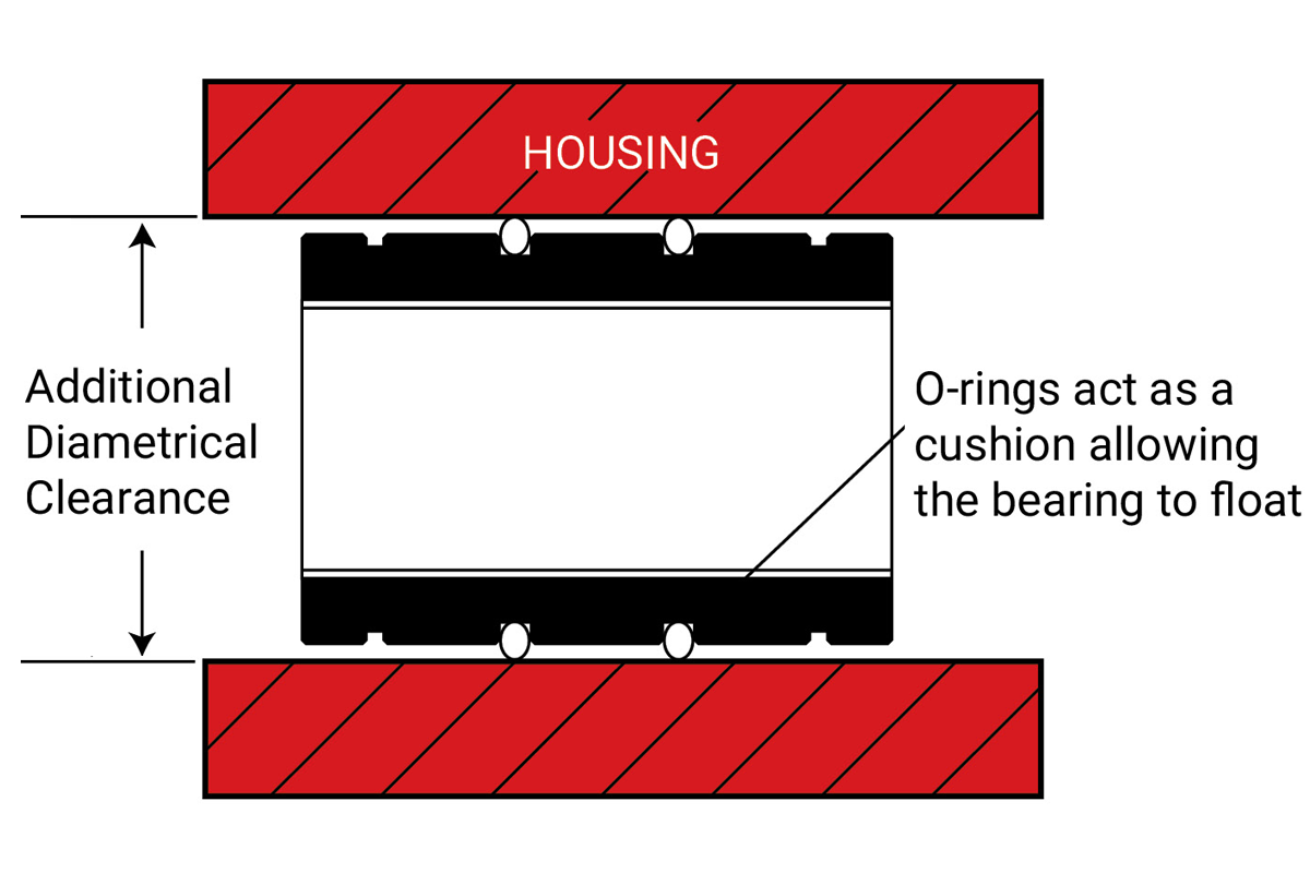
POSSIBLE SOLUTIONS for use with Standard “FL”:
- Undersize the bearing O.D. (see chart) and install o-rings
- Oversize the housing I.D. (see chart) and install the standard bearing with o-rings.
The additional clearance created by either method will allow the bearing to float in the housing and match the non-parallelism of the shafting.
The recommended method of retention for this mounting is a snap ring at each end.
Note: Do not use epoxy in this configuration. It will lock the bearing in place, not allowing it to self-align.
⚠ CAUTION
This solution is only for SEVERE cases that the standard self-aligning will not accommodate.
| Part No. | MAX Additional Clearance in. |
|---|---|
| FL03 | 0.0070 |
| FL04 | 0.0080 |
| FL06 | 0.0080 |
| FL08 | 0.0080 |
| FL10 | 0.0100 |
| FL12 | 0.0100 |
| FL16 | 0.0120 |
| FL20 | 0.0120 |
| FL24 | 0.0120 |
| FL32 | 0.0120 |
| FL40 | 0.0160 |
| FL48 | 0.0160 |
| FL64 | 0.0200 |
| Part No. | MAX Additional Clearance mm |
|---|---|
| FM05 | 0.203 |
| FM08 | 0.203 |
| FM10 | 0.203 |
| FM12 | 0.203 |
| FM16 | 0.254 |
| FM20 | 0.254 |
| FM25 | 0.305 |
| FM30 | 0.305 |
| FM40 | 0.305 |
| FM50 | 0.305 |
| FM60 | 0.406 |
| FM80 | 0.508 |
| Part No. | MAX Additional Clearance mm |
|---|---|
| FMT06 | 0.203 |
| FMT08 | 0.203 |
| FMT10 | 0.203 |
| FMT12 | 0.203 |
| FMT14 | 0.203 |
| FMT16 | 0.254 |
| FMT20 | 0.254 |
| FMT25 | 0.254 |
| FMT30 | 0.305 |
| FMT40 | 0.305 |
| FMT50 | 0.305 |
| Part No. | MAX Additional Clearance mm |
|---|---|
| FG06 | 0.203 |
| FG08 | 0.203 |
| FG10 | 0.203 |
| FG12 | 0.203 |
| FG15 | 0.254 |
| FG16 | 0.254 |
| FG18 | 0.254 |
| FG20 | 0.254 |
| FG25 | 0.305 |
| FG30 | 0.305 |
| FG35 | 0.305 |
| FG40 | 0.305 |
| FG50 | 0.305 |
| Part No. | MAX Additional Clearance mm |
|---|---|
| FJ06 | 0.203 |
| FJH08 | 0.203 |
| FJ08 | 0.203 |
| FJ10 | 0.203 |
| FJ12 | 0.203 |
| FJ13 | 0.203 |
| FJ16 | 0.254 |
| FJ20 | 0.254 |
| FJ25 | 0.305 |
| FJ30 | 0.305 |
| FJ35 | 0.305 |
| FJ38 | 0.305 |
| FJ40 | 0.305 |
| FJ50 | 0.406 |
| FJ60 | 0.406 |
| FJ80 | 0.508 |
| FJ100 | 0.61 |
| FJ120 | 0.61 |
| FJ150 | 0.61 |
Chemical Reaction Chart
The original Frelon® J has almost universal chemical inertness. Only molten sodium and fluorine at elevated temperatures and pressures show any signs of attack. It is approved for use with liquid oxygen, N202 hydrazine, UDMH, hydrocarbon fuels, high strength hydrogen peroxide, etc.
The FrelonGOLD® material is a composite of PTFE and a bearing filler. The PTFE is chemically inert. The chemical resistance shown in the chart below is defined by the compatibility of the filler with the various chemicals.
Other data in the chart below applies to the bearing shell and pillow block materials. The table is provided as a reference only. The data given will be affected by factors such as temperature, PV, degree of contact, strength of solution, etc. In each specific application, it is always advisable to conduct specific testing to determine suitability of use. This table only addresses general corrosion, NOT galvanic, SCC, or other types of corrosion. Corrosion rates are at room temperature unless otherwise noted.
Standard and hard coat data only apply when the coating is intact. If the coating is worn through or damaged, an area of galvanic and pitting corrosion will be created. Then use the bare aluminum data.
Standard Simplicity® products use aluminum alloy, which is known to have the best corrosion resistance of the high strength aluminum alloys. The sulfuric bath anodizing and nickel acetate sealing provide the best corrosion resistance available in anodized coatings. They can withstand a rigorous 14-day exposure in a 5% salt spray solution at 96°F per military specifications without significant damage. With the coating intact, it is considered to be inert in most fluids with a pH value between 5 and 8. Hard coat anodizing provides the same chemical resistance but is applied to a 0.002" thickness, providing a more durable surface that will stand up to greater abuse. However, if the coating is penetrated, the resistance is reduced.
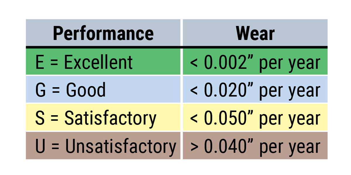
Special stainless steel bearings use AISI 316 stainless, which has superior resistance over 303, 304, 420, 440, 17-4PH, and most other common stainless grades. 316 is generally considered to be the most corrosion resistant of conventional stainless steels.
Note: This information was compiled for Pacific Bearing® Company by Materials Engineering, Inc. of Virgil, IL. This specification information is believed to be accurate and reliable, however, no liability is assumed. Information is for reference only. User must test specific applications.
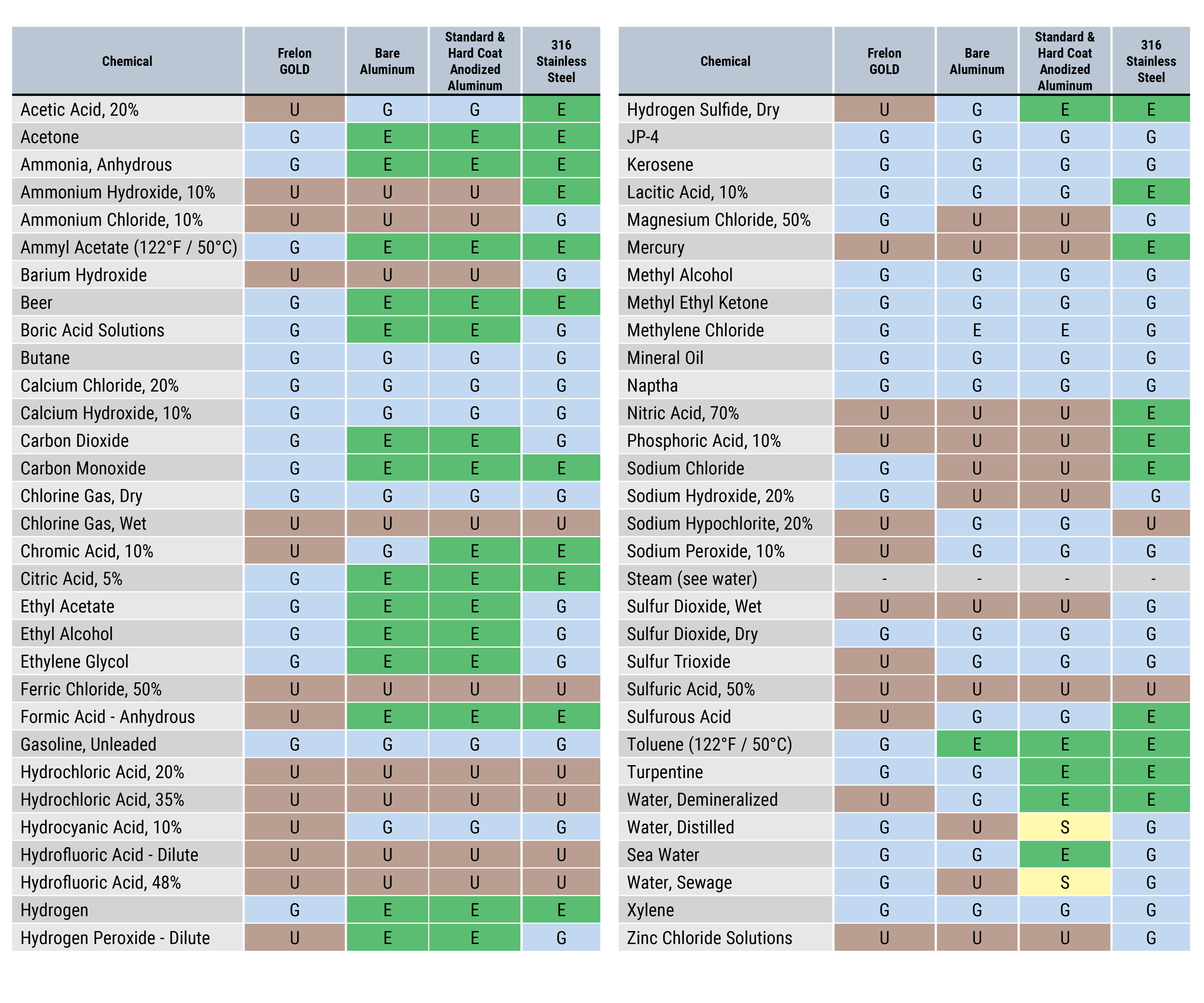
Linear Ball Bearings Technical
Information
Load Rating and Life Expectancy
The life (L) of a linear bearing can be obtained from the following equation with the basic dynamic load rating and the load applied to the bearing:
\( L = \left( \frac{f_H \cdot f_T \cdot f_C }{f_W} \cdot \frac{C}{P} \right)^3 \cdot 50 \)
\( L \): Rated life (km)
\( C \): Basic dynamic load rating (N/lbf)
\( P \): Working load (N/lbf)
\( f_W \): Load coefficient
\( f_H \): Hardness factor
\( f_T \): Temperature coefficient
\( f_C \): Contact coefficient
The lifespan Lh of a linear ball bearing in hours can be obtained by calculating the traveling distance per unit time. The lifespan can be obtained from the following equation if the stroke length and the number of strokes are constant:
\( L_h = \left( \frac{L \cdot 10^3}{2 \cdot s \cdot n_1 \cdot 60} \right) \)
\( L_h \): Lifespan (hr)
\( L \): Rated life (km)
\( s \): Stroke length (m)
\( n_1 \): Number of strokes per minute (cpm)
50: Constant base line (km)
Relation Between Ball Circuits and Load Rating
Linear ball bearings are constructed so that the ball circuits are spaced equally. The load rating varies according to the loaded position. The load ratings of the linear ball bearings from the dimensional tables are per track and increased loading can be achieved by equally sharing the load between the tracks.
The table shows the increased value by the number of ball circuits in such cases.
Notes:
(1) 3 track bearing is equal.
(2) Open bearing load is de-rated by 50% if going against the opening.
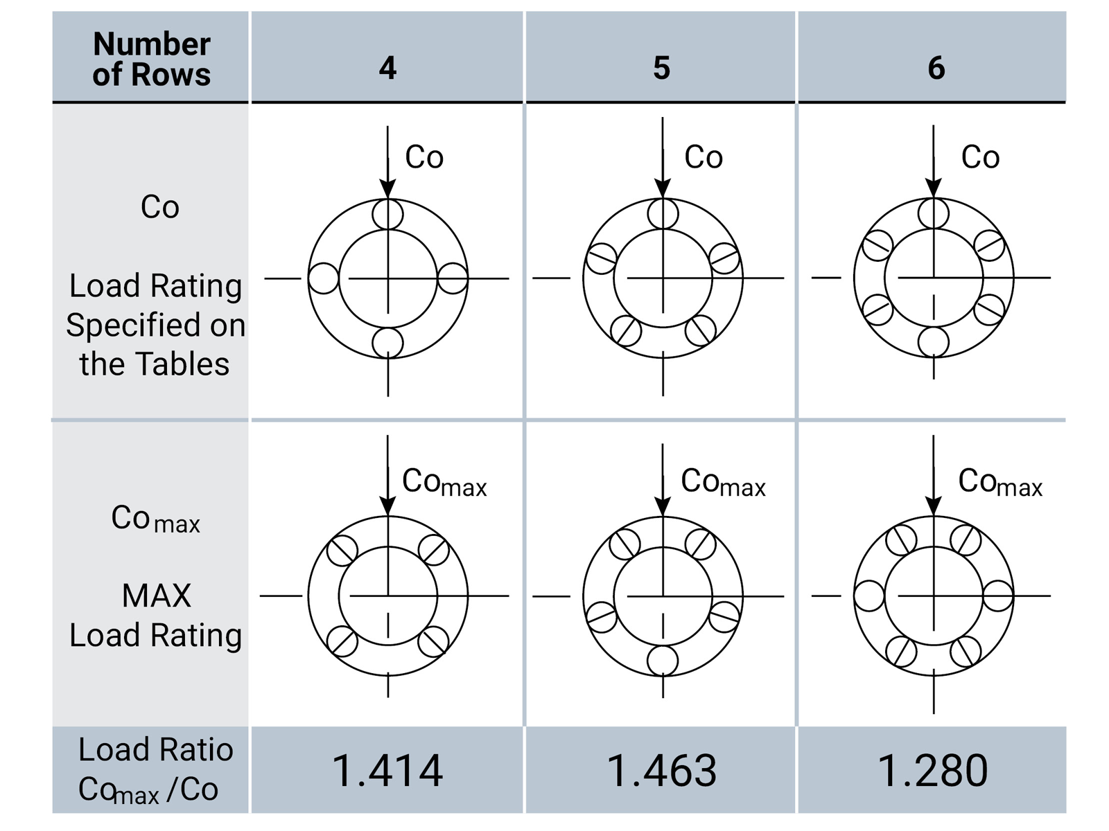
Sample Calculations
- Obtaining the rated life L and lifespan LH of the Simplicity® linear ball bearing used in the following conditions:
- Linear ball bearing: EP20G
- Stroke length: 50 mm
- Number of strokes per minute: 50 cpm
- Load per bush: 490 N
The basic dynamic load rating of the linear ball bearing is 860 N from the dimension tables on page 79. From equation (1), therefore, the rated life L is obtained as follows:
\( L = \left( \frac{f_H \cdot f_T \cdot f_C }{f_W} \cdot \frac{C}{P} \right)^3 \cdot 50 \qquad F_H=F_T=FC=FW=1.0 \)
\( L = \left( \frac{860}{490}\right)^3 \cdot 50 = 270 \, km \)
From equation (2), the lifespan Lh is obtained as follows:
\( L_h = \left( \frac{L \cdot 10^3}{2 \cdot s \cdot n_1 \cdot 60} \right) \)
\( L_h = \left( \frac{270 \cdot 10^3}{2 \cdot 0.05 \cdot 50 \cdot 60} \right) = 901 \, hr \)
- Select the ball bearing type by satisfying the following conditions:
- Number of linear bushing used: 4
- Stroke length: 1 m
- Traveling speed: 10 m/min.
- Number of strokes per minute: 5 cpm
- Lifespan: 10,000 hr
- Total load: 980 N
From equation (2), the traveling distance within the lifespan is obtained as follows:
\( L = 2 \cdot s \cdot n_1 \cdot 60 \cdot L_h = 6,000 \, km \)
From equation (1), the basic dynamic load rating is obtained as follows:
\( C = \sqrt[3]{\frac{L}{50}} \cdot \left( \frac{f_W \cdot f_H}{f_T \cdot f_C} \right) \cdot P = 1492 \, \text{N} \)
Assume the following with a pair of shafts each with two linear ball bearings:
\( f_C \) = 0.81 \( f_W \) = \( f_T \) = \( f_F \) = 1
As a result, EP20G is selected from the dimension table as the Simplicity® linear ball bearing type satisfying the value of C.
Linear Ball Bearings Load Rating
& Rating Life
Load Rating
Basic Dynamic Load Rating (C)
This term is arrived at based on an evaluation of a number of identical linear systems individually run in the same conditions, if 90% of them can run with the load (with a constant value in a constant direction) for a distance of 50 km without damage caused by rolling fatigue. This is the basis of the rating.
Allowable Static Moment (M)
This term defines the allowable limit value of static moment load, with reference to the amount of permanent deformation similar to that used for evaluation of basic rated load (Co).
Static Safety Factor (fs)
This factor is used based on the application condition.
Static Safety Factors Table 1
| Condition of use | Low Limit of fs |
|---|---|
| When the shaft has less deflection and shock | 1 to 2 |
| When elastic deformation should be considered with respect to cantilever load | 2 to 4 |
| When the equipment is subject to vibration and impacts | 3 to 5 |
Basic Static Load Rating (Co)
This term defines a static load such that, at the contacting position where the maximum stress is exercised, the sum of the permanent deformation of the rolling elements and that of the rolling plain is 0.0001 times of the diameter of the rolling elements.
Rating Life
Rating Life of the Linear System
As long as the linear system reciprocates while being loaded, continuous stress can cause flaking on the rolling bodies and planes due to material fatigue. The system’s distance of travel until the first flaking occurs is called the life of the system. The life of the system varies even when similar conditions are used – dimensions, structure, material, heat treatment, and processing method. The material fatigue causes the essential variations. The rating life defined bellow is used as an index for the life expectancy of the linear system.
Rating Life (L)
Rating life is the total travelling distance that 90% of a group of systems of the same size can reach without causing any flaking when they operate under the same conditions. The rating life can be obtained from the following equation with the basic dynamic load rating and the load on the linear system:
For ball type:
\( L = \left( frac{C}{p}^3 \right) \cdot 50 \)
\( L \): Rating life (km)
\( C \): Basic dynamic load rating (N)
\( p \): Load (N)
Consideration and influence of vibration impact loads and distribution of load should be taken into account when designing a linear motion system. It is difficult to calculate the actual load. The rating life is also affected by the operating temperature. In these conditions, the expression (1) is arranged as follows:
\( L = \left( \frac{f_H \cdot f_T \cdot f_C }{f_W} \cdot \frac{C}{P} \right)^3 \cdot 50 \)
For ball type:
\( L \): Rating life (km)
\( f_H \): Hardness factor
\( C \): Basic dynamic load rating (N)
\( f_T \): Temperature coefficient
\( p \): Load (N)
\( f_C \): Contact coefficient
\( f_W \): Load coefficient
The rating life in hours can be calculated by obtaining the travelling distance per unit time. The rating life in hours can be obtained from the following expression when the stroke length and the number of strokes are constant:
\( L_h = \left( \frac{L \cdot 10^3}{2s \cdot n_1 \cdot 60} \right) \)
\( L_h \) = Rating life in hours (hr)
\( s\) = Stroke length (m)
\( L\) = Rating life (km)
\( n_1\) = No. of strokes per minute (cpm)
Hardness Factor (fH)
The shaft must be sufficiently hardened when a linear bushing is used. If not properly hardened, permissible load is lowered and the life of the linear ball bearings will be shortened.
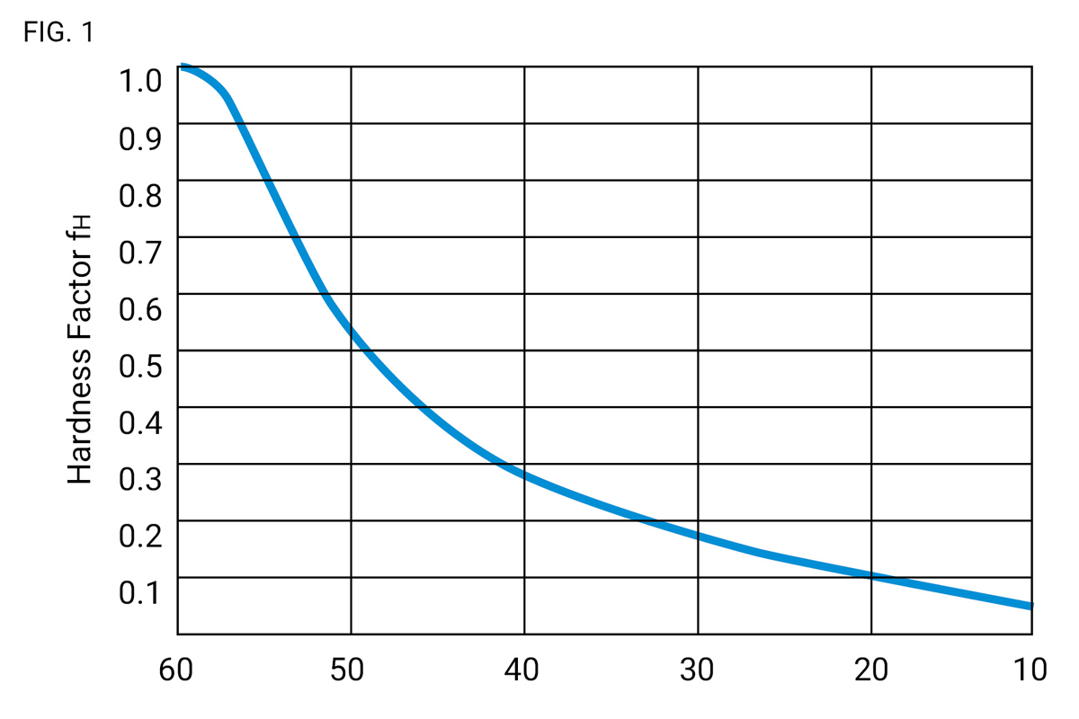
Temperature Coefficient (fT)
If the temperature of the linear system exceeds 100°C, hardness of the linear system and the shaft lowers to decrease the permissible load compared to that of the linear system used at room temperature. As a result, the abnormal temperature rise shortens the rating life.
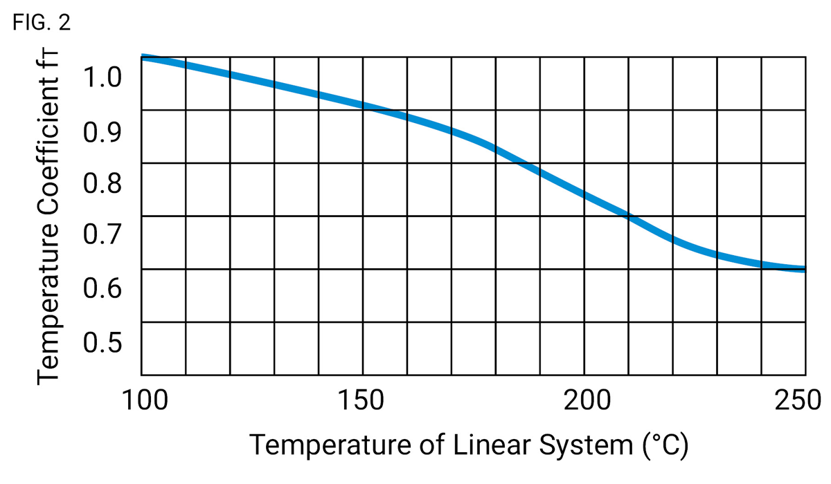
Notes: Maximum temperature of plastic retainer 212°F or 100°C. Maximum temperature 176° per Table 6
Contact Coefficient (fc) – Table 2
Generally two or more linear bearings are used on one shaft. Thus, the load on each linear system differs depending on each processing accuracy. Because the linear bushings are not loaded equally, the number of linear bushings per shaft changes the permissible load off the system.
Contact Coefficient Table 2
| Number of Linear Systems per Shaft | Contact coefficient - FC |
|---|---|
| 1 | 1.00 |
| 2 | 0.81 |
| 3 | 0.72 |
| 4 | 0.66 |
| 5 | 0.61 |
Load Coefficient (fw) – Table 3
When calculating the load on the linear system, it is necessary to accurately obtain object weight, inertial force based on motion speed, moment load, and each transition as time passes. However, it is difficult to calculate those values accurately because reciprocating motion involves the repetition of start and stop as well as vibration and impact. A more practical approach is to obtain the load coefficient by taking the actual operating conditions into account.
Load Coefficient Table 3
| Operating Conditions | FW |
|---|---|
| Operation at low speed (15 m/min. or less) without impulsive shock from outside | 1.0 to 1.5 |
| Operation at intermediate speed (60 m/min. or less)without impulsive shock | 1.0 to 2.0 |
| Operation at high speed (over 60 m/min.) with impulsive shock from outside | 2.0 to 3.5 |
Linear Ball Bearings Clearance
& Mounting
Clearance & Fit
Standard-type Simplicity® linear ball bearings matched to a shaft that provides inadequate clearance may result in early bearing failure and/or rough linear motion. The clearance adjustable linear ball bearings and open linear ball bearings can be adjusted when assembled in the housing by controlling the housing bore. However, too much clearance will increase the deformation of the linear ball bearing, which will affect its precision and life. Therefore, the appropriate clearance between the ball bearing and shaft, and the appropriate linear ball bearing housing bore are required based on application.
Recommended Fit of Linear Ball Bearings Table 4
| Model | Division | Shaft | Housing | ||
|---|---|---|---|---|---|
| Normal Fit | Transitional | Loose Fit | Tight Fit | ||
| JP | High Precision | g6 | h6 | H7 | J7 |
| IP | High Precision | g6 | h6 | H7 | J7 |
| EP | High Precision | h6 | j6 | H7 | J7 |
Shaft & Housing
To optimize performance of the Simplicity® linear ball bearing it is recommended that a high precision shaft and pillow block are required.
Shaft
The rolling balls in linear ball bearings are in-line contact with the shaft surface. Therefore, the shaft dimensions, tolerance, surface finish, and hardness greatly affect the performance of the linear ball bearing. The shaft should be manufactured to the following tolerances:
- Surface finish critically affects the smooth rolling of balls; shaft surface finish should be Ra 8-10.
- Shaft hardness should be HRC 60 to 64. Hardness less than HRC 60 will decreases the life/load.
- Preload increases the frictional resistance slightly. If the preload is too tight, the deformation of the bearing sleeve will shorten the linear ball bearing’s life.
Housing
There are a wide variety of housings differing in design, machining, and mounting. See mounting requirements below.
Mounting
When inserting the linear ball bearing into the housing, do not hit the linear ball bearing on the end-retaining ring, but apply pressure either by hand or arbor on the linear ball bearing sleeve (See Fig.1). To insert the shaft into the mounted linear ball bearing, make sure the shaft is chamfered and be careful not to push on the balls by inserting the shaft at an angle.
Note: If two shafts are used in parallel, the parallelism is an important factor to assure smooth linear movement and not damage the linear ball bearings.
Examples of Mounting:
The popular way to mount linear ball bearings is with a slight preload. PBC Linear recommends a slight clearance fit-up to ensure proper life. The examples, Figs. 2 to 6, show the inserted linear ball bearing using a variety of retention methods.
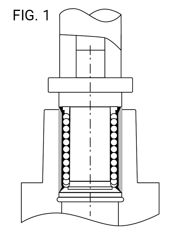
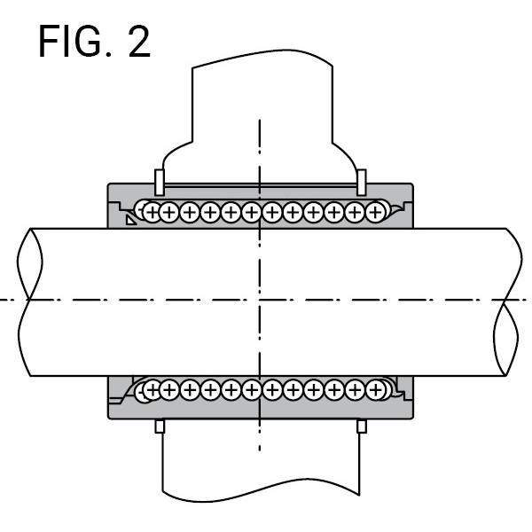
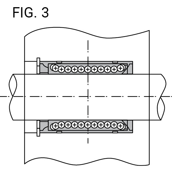
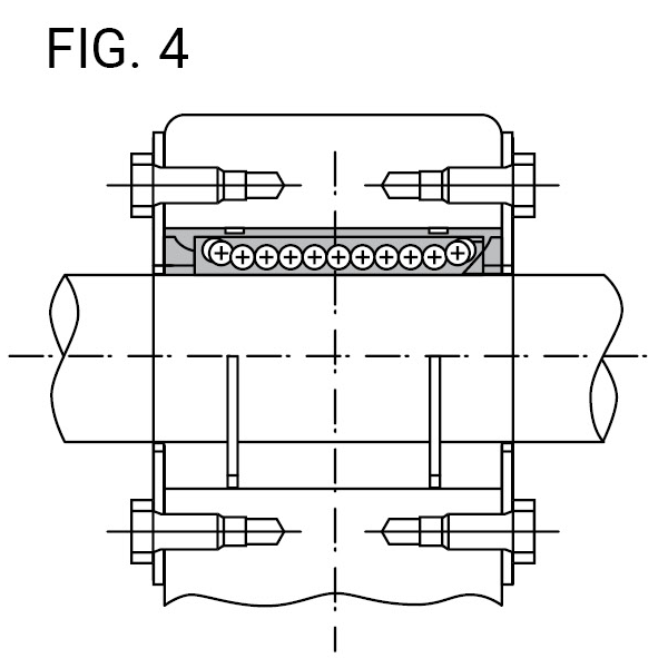
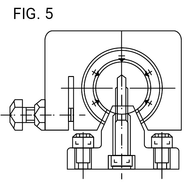
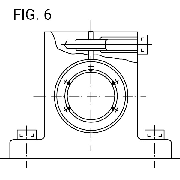
Frictional Resistance
The static frictional resistance of the Simplicity® linear system is so low that it is only slightly different from the kinetic frictional resistance, enabling smooth linear movement from low to high speeds. In general, the frictional resistance is expressed by the following equation.
\( F = \mu \cdot W + f \)
\( F \): Frictional resistance
\( W \): Load weight
\( \mu \): Coefficient of friction
\( f \): Sealing resistance
The frictional resistance of each PBC Linear system depends on the model, load weight, speed, and lubricant. The sealing resistance depends on the lip interference and lubricant, regardless of the load weight. The sealing resistance of one linear system is about 200 to 500 gf. The coefficient of friction depends on the load weight, moment load, and preload.
Coefficient of Linear System Friction (µ) Table 5
| Linear System Type | Models | Coefficient of Friction (µ) |
|---|---|---|
| Linear Bearing | JP, EP, IP | 0.002 to 0.003 |
Ambient Working Temperature
The ambient working temperature range for each PBC linear system depends on the model. Consult PBC Linear on use outside the recommended temperature range.
Temperature conversion equation:
\( C = \frac{5}{9} \left(F - 32 \right) \)
\( F = 32 + \frac{9}{5}C \)
Ambient Working Temperature Table 6
| Linear System Type | Models | Ambient Working Temperature |
|---|---|---|
| Linear Ball Bearing | JP, EP, IP | -20 to 80°C, -4 to 176°F |
Lubrication and Dust Prevention
Using PBC Linear systems without lubrication increases the abrasion of the rolling elements, shortening the life span. Systems, therefore, require appropriate lubrication. PBC Linear ball bearings are shipped with an anti-corrosion treatment, which must be cleaned prior to applying grease or oil. For lubrication, PBC Linear recommends turbine oil conforming to ISO Standards G32 to G68 or lithium base soap grease No.2. Prior to usage, apply lubricant directly inside the linear bearing and shaft, and re-lubricate periodically according to the operating conditions. Some systems from PBC Linear are sealed to block dust out and seal lubricant in. If used in a harsh or corrosive environment a protective cover should be used.
Roller Pillow Block Bearings Loads
Orientation & Cantilever Loads
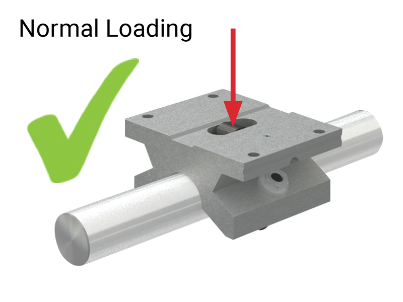
When a linear motion system is subjected to a cantilever load or moment, the system designer must take into consideration these type of loads will greatly affect the performance of the system. Roller Pillow Blocks are not suitable for these types of applications because the moments will load the side rollers and cause premature failure. If the moments or cantilever loads are minor, loads may be acceptable. For this reason we ask that you consult the factory.
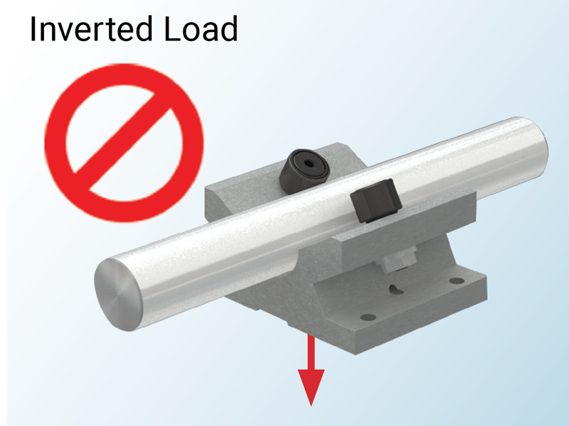
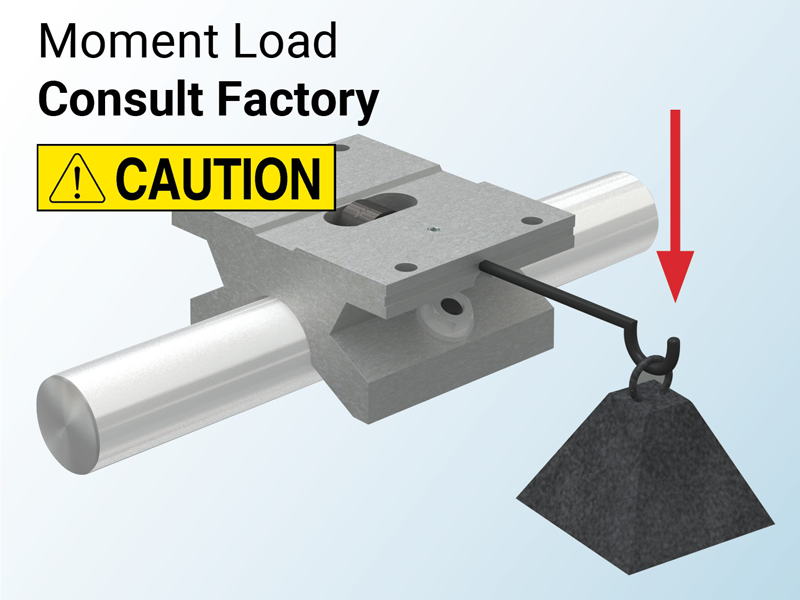
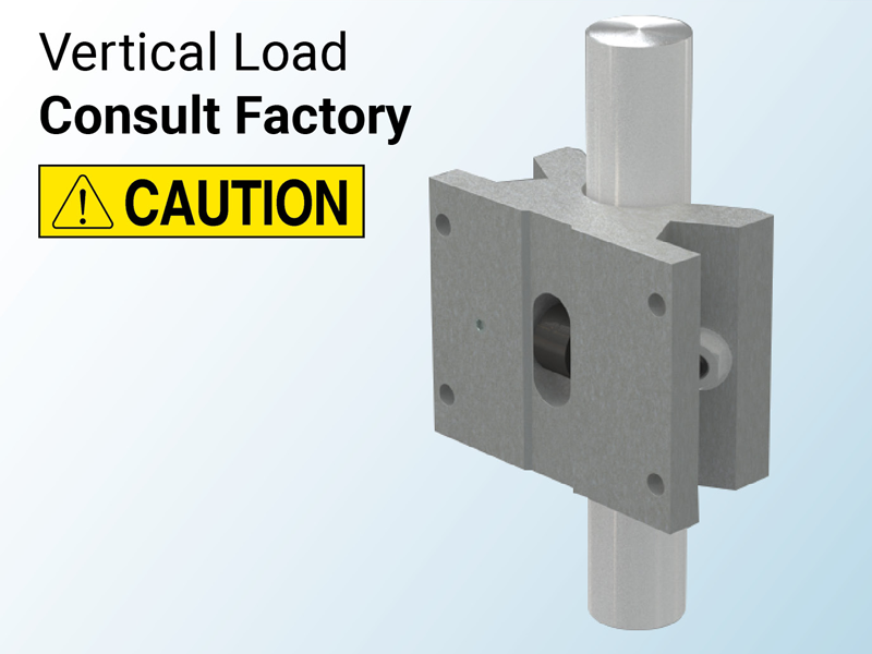
Determining Pillow Block Size & Model
To determine the proper size Roller Pillow Block for an application, refer to the chart using the worst-case load and the required travel life. Select the Roller Pillow Block above where the lines intersect. This should be suitable for anticipated travel life and loading.
Note: Shock, vibration, and moments may affect the life of the pillow block.
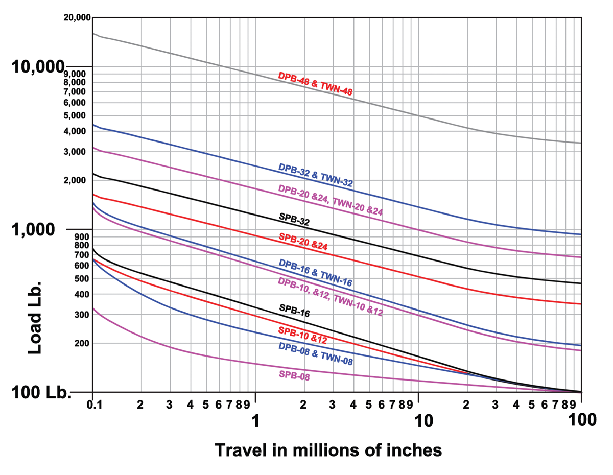
Note: Chart is rated at 10% accuracy. Figures are based on a safety factor of one.
Roller Pillow Block Bearings
Adjustments & Curves
Adjustments
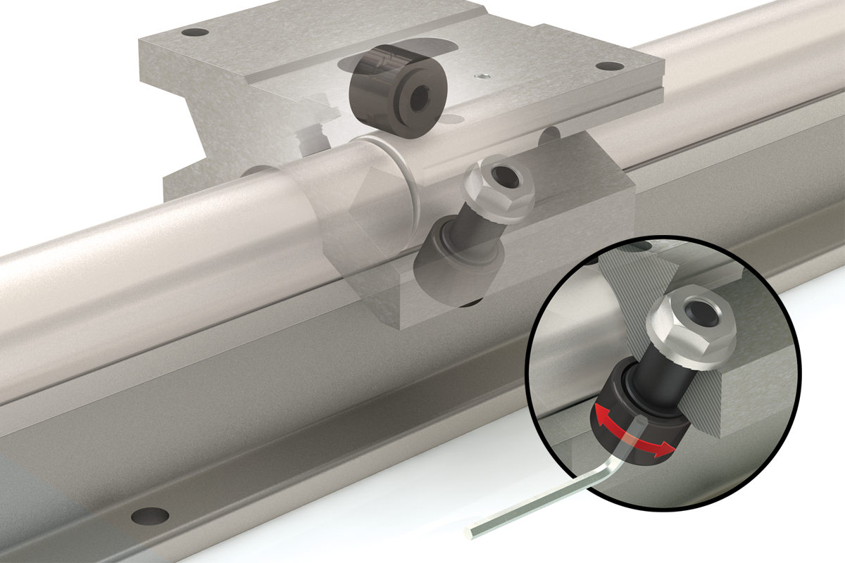
Roller Pillow Blocks are factory set for Simplicity® 60 Plus® shafting. Adjustments can be made to the eccentric cam follower to either increase or decrease the shaft clearance.
Located on the same side of the Roller Pillow Block as the set screw, the eccentric cam follower is adjusted by using a stubby allen wrench while allowing a 0.002" feeler gauge to freely move between the shaft and the eccentric roller. The fixed side must remain in contact with the shaft. If care is taken not to overload the roller, then a slight preload is possible. Rollers should never be tightened to the point where they cannot move freely.
Turning a Curve
A single Roller Pillow Block has the ability to turn a curve or run on a non-linear system. The following table lists the minimum track radius that the single Roller Pillow Block can tolerate without additional alteration.
| Pillow Block Size | Minimum Shaft Radius |
|---|---|
| 8 | 6" |
| 10 | 12" |
| 12 | 14" |
| 16 | 18" |
| 20 | 36" |
| 24 | 40" |
| 32 | 44" |
| 48 | 52" |
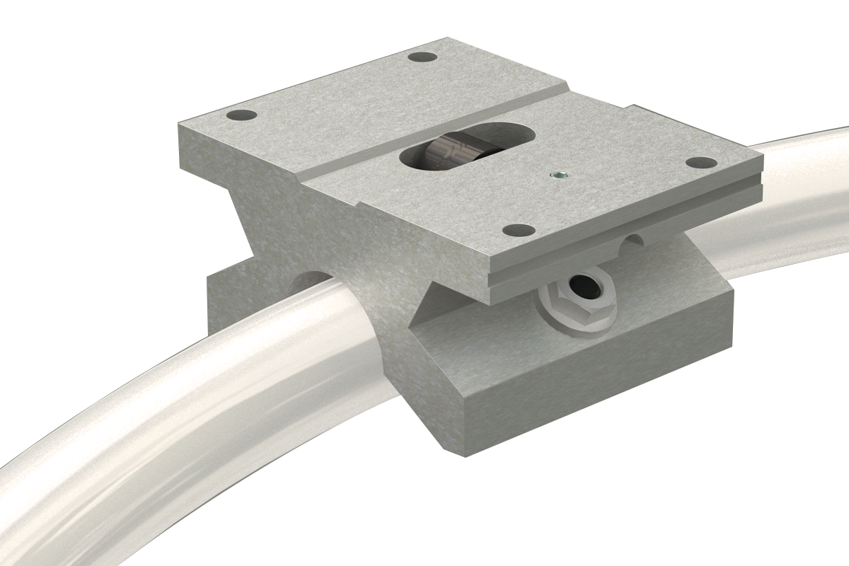
Lubrication, Rails & Bearings
The rollers are internally lubricated for life, but the rails must always have a layer of grease. As a guideline, reapply fresh grease every 50,000 cycles.
Roller Pillow Block Bearings
Cross Reference Guide
Cross Reference Guide
Below is a chart that cross-references our product with competitors. For more assistance, please consult the factory.
Standard Linear Ball Bearings
| PBC Linear | PBC Linear Sealed | Thomson | Thomson Sealed | INA | INA Sealed | NB Steel Retainer | NB Steel Retainer Sealed | NB Plast’c Retainer | NB Plast’c Retainer Sealed |
|---|---|---|---|---|---|---|---|---|---|
| IP4G-0S | IP4G | A4812 | KBZ04 | KBZ04PP | SW4 | SW4UU | SW4G | SW4GUU | |
| IP6G-0S | IP6G | A61014 | KBZ06 | KBZ06PP | SW6 | SW6UU | SW6G | SW6GUU | |
| IP8G-0S | IP8G | A81420 | A81420DD | KBZ08 | KBZ08PP | SW8 | SW8UU | SW8G | SW8GUU |
| IP10G-0S | IP10G | A101824 | KBZ10 | KBZ10PP | SW10 | SW10UU | SW10G | SW10GUU | |
| IP12G-0S | IP12G | A122026 | A122026DD | KBZ12 | KBZ12PP | SW12 | SW12UU | SW12G | SW12GUU |
| IP16G-0S | IP16G | A162536 | A162536DD | KBZ16 | KBZ16PP | SW16 | SW16UU | SW16G | SW16GUU |
| IP20G-0S | IP20G | A203242 | KBZ20 | KBZ20PP | SW20 | SW20UU | SW20G | SW20GUU | |
| IP24G-0S | IP24G | A243848 | KBZ24 | KBZ24PP | SW24 | SW24UU | SW24G | SW24GUU | |
| IP32G-0S | IP32G | A324864 | KBZ32 | KBZ32PP | SW32 | SW32UU | SW32G | SW32GUU |
Open Type Linear Ball Bearings
| PBC Linear | PBC Linear Sealed | Thomson | Thomson Sealed | INA | INA Sealed | NB Steel Retainer | NB Steel Retainer Sealed | NB Plast’c Retainer | NB Plast’c Retainer Sealed |
|---|---|---|---|---|---|---|---|---|---|
| IP8G-OP-0S | IP8G-OP | OPN81420 | OPN81420DD | KBZO8OP | KBZO8OPPP | SW8OP | SW8OPUU | SW8GOP | SW8GOPUU |
| IP10G-OP-0S | IP10G-OP | OPN101824 | KBZ10OP | KBZ10OPPP | SW10OP | SW10OPUU | SW10GOP | SW10GOPUU | |
| IP12G-OP-0S | IP12G-OP | OPN122026 | OPN122026DD | KBZ12OP | KBZ12OPPP | SW12OP | SW12OPUU | SW12GOP | SW12GOPUU |
| IP16G-OP-0S | IP16G-OP | OPN162536 | OPN162536DD | KBZ16OP | KBZ16OPPP | SW16OP | SW16OPUU | SW16GOP | SW16GOPUU |
| IP20G-OP-0S | IP20G-OP | OPN203242 | KBZ20OP | KBZ20OPPP | SW20OP | SW20OPUU | SW20GOP | SW20GOPUU | |
| IP24G-OP-0S | IP24G-OP | OPN243848 | KBZ24OP | KBZ24OPPP | SW24OP | SW24OPUU | SW24GOP | SW24GOPUU | |
| IP32G-OP-0S | IP32G-OP | OPN324864 | KBZ32OP | KBZ32OPPP | SW32OP | SW32OPUU | SW32GOP | SW32GOPUU |
High Load Self Aligning Linear Ball Bearings
| PBC Linear | Thomson | INA | NB |
|---|---|---|---|
| IPS6 | SUPER6 | KX6PP | TW6UU |
| IPS8 | SUPER8 | KX8PP | TW8UU |
| IPS10 | SUPER10 | KX10PP | TW10UU |
| IPS12 | SUPER12 | KX12PP | TW12UU |
| IPS16 | SUPER16 | KX16PP | TW16UU |
| IPS20 | SUPER20 | KX20PP | TW20UU |
| IPS24 | SUPER24 | KX24PP | TW24UU |
| IP8-OP | SUPER8OPN | KX08PP | TW8OPUU |
| IP10-OP | SUPER10OPN | KXO10PP | TW10OPUU |
| IP12-OP | SUPER12OPN | KXO12PP | TW12OPUU |
| IP16-OP | SUPER16OPN | KXO16PP | TW16OPUU |
| IP20-OP | SUPER20OPN | KXO20PP | TW20OPUU |
| IP24-OP | SUPER24OPN | KXO24PP | TW24OPUU |
| PBC Linear | Thomson | INA | NB |
|---|---|---|---|
| IPPS08-GL | SPB8UU | KGX8PP | TWA8UU |
| IPPS10-GL | SPB10UU | KGX10PP | TWA10UU |
| IPPS12-GL | SPB12UU | KGX12PP | TWA12UU |
| IPPS16-GL | SPB16UU | KGX16PP | TWA16UU |
| IPPS20-GL | SPB20UU | KGX20PP | TWA20UU |
| IPPS24-GL | SPB24UU | KGX24PP | TWA24UU |
| IPPNS08-GLP | SPB8OPN | KGXO8PP | TWD8UU |
| IPPNS10-GLP | SPB10OPN | KGXO10PP | TWD10UU |
| IPPNS12-GLP | SPB12OPN | KGXO12PP | TWD12UU |
| IPPNS16-GLP | SPB16OPN | KGXO16PP | TWD16UU |
| IPPNS20-GLP | SPB20OPN | KGXO20PP | TWD20UU |
| IPPNS24-GLP | SPB24OPN | KGXO24PP | TWD24UU |