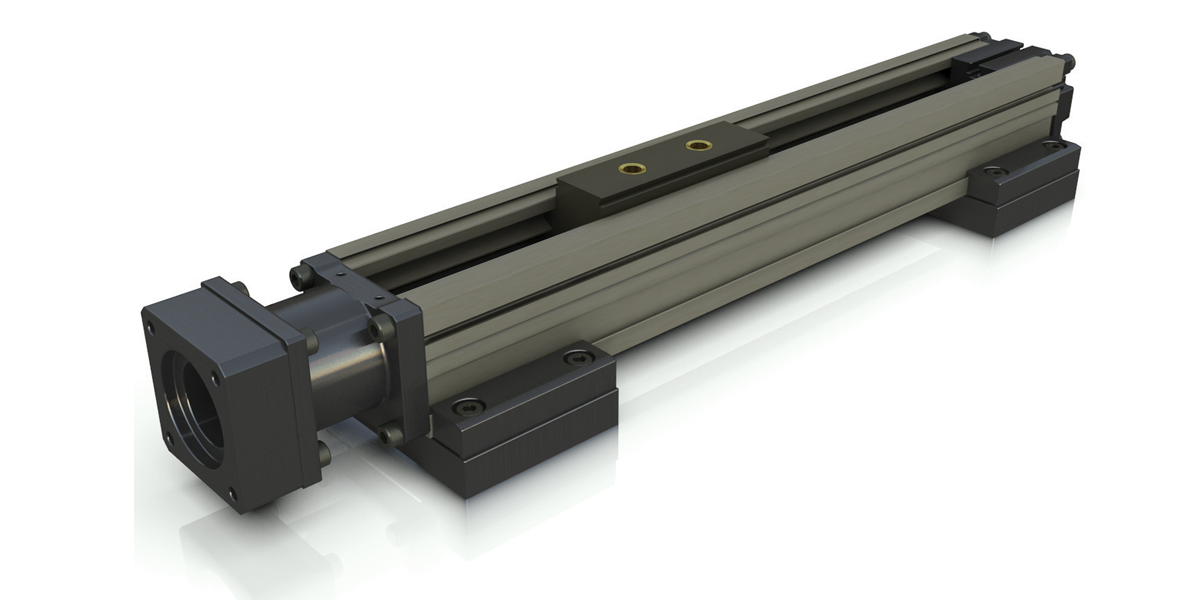
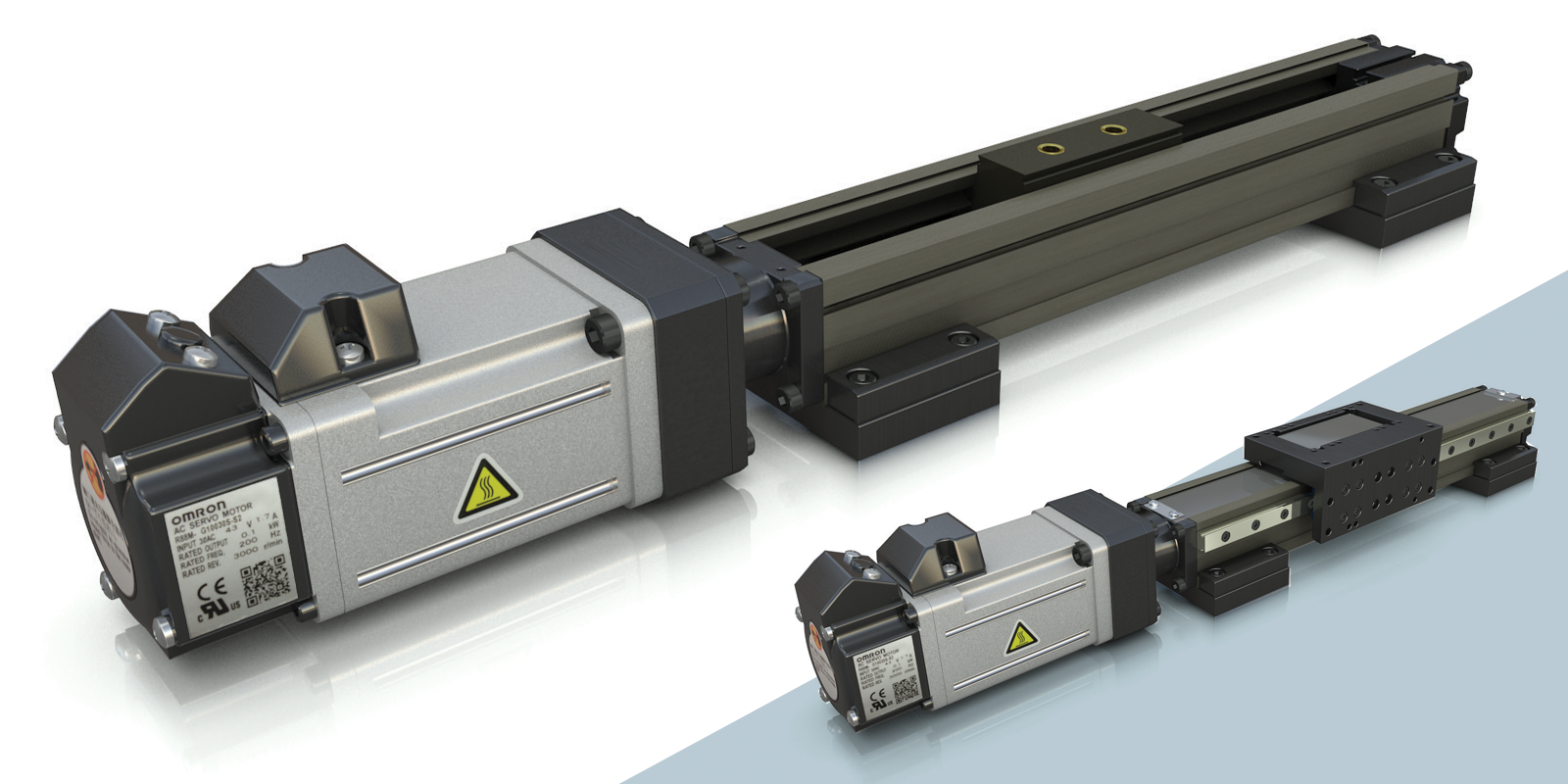
ML Series
Miniature Linear Actuators
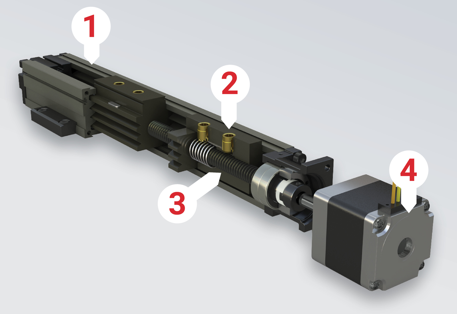
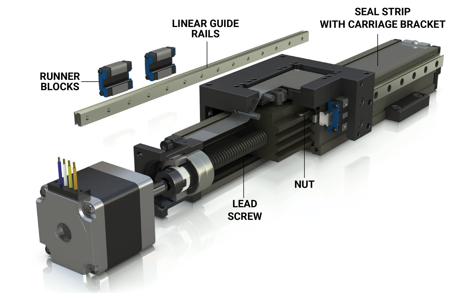
ML Series Overview
1. Rail/Housing
SIMO® process ensures precision mounting, accurate installation and lightweight composition. Ceramic Coated Body for corrosion resistance and long life.
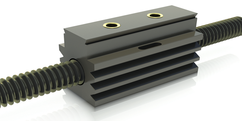
2. Nut
- Brass Inserts for system mounting and integrity.
- Built-in magnet accommodates home, limit and position sensors.
- Anti-Backlash Nut (Optional) for applications which require high bi-directional accuracy and repeatability.
3. Lead Screw
Large diameter, antifriction coated screw allows for longer lengths by decreasing screw whip and increasing column strength. 1 mm, 2 mm, 5 mm, 10 mm, 12 mm, 16 mm, 25 mm, and 38 mm leads.
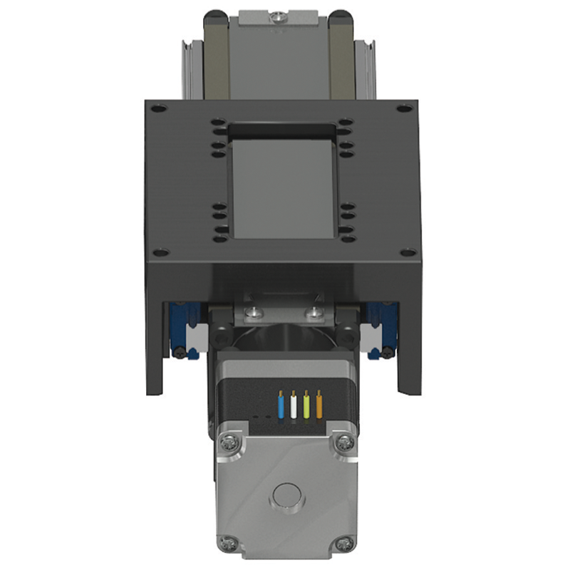
4. Motor
Stepper motors available in standard NEMA 11, 14, 17, 23, metric frame sizes or add
your own.
Servo motors available in 40 and 60 mm motors.
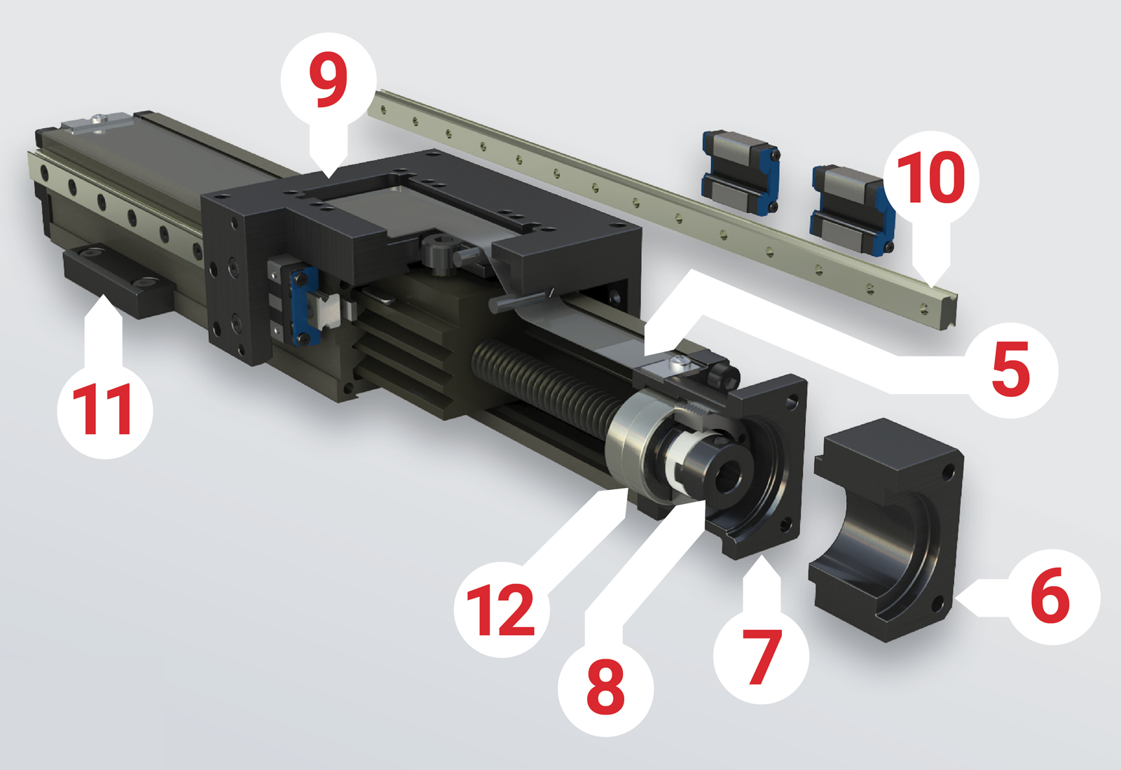
5. Seal Strip
Ultra-wear-resistant MDS nylon prevents particulates or contaminants from entering or exiting actuator.
6. Motor Mount Adapter (MLC)
Adapter plate designed to fit any manufacturer’s motor. Compensates for variations in pilot diameter, depth, shaft diameter, length and mounting screw patterns.
7. Motor Mount
Specially constructed with an optimized length, resulting in an overall shorter system with PBC Linear™ brand stepper motors.
8. Internal Coupling
Rigid polymer insert coupling for increased smoothness and minimal backlash.
9. “Dovetail” Style Carriage
PTFE polymer material has fourteen plain bearing surfaces providing low friction for smooth and quiet linear motion. Notched “dovetail” carriage provides easier alignment and assembly. Features extra mounting holes for ease of installation and multi-axis assemblies.
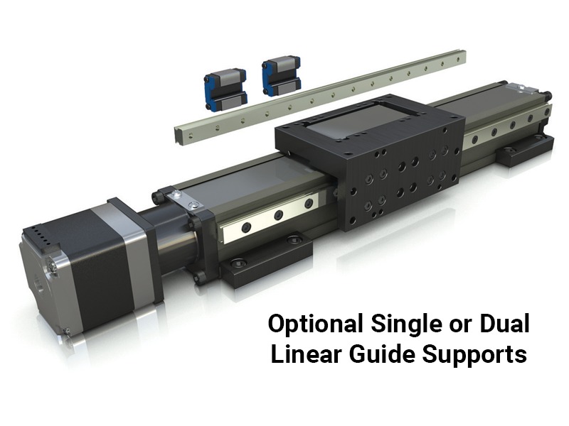
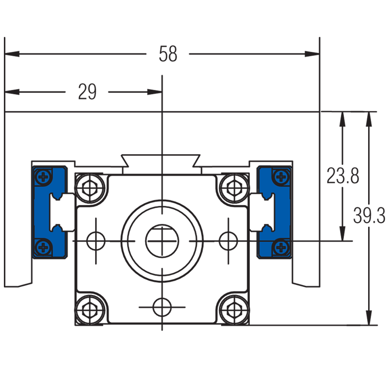
10. Linear Guide Supports
Provide increased load and moment capacities and overall rigidity to the system. Available single or dual rails with one or two runnerblocks per rail.
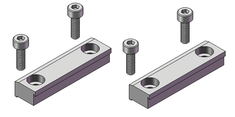
11. Dovetail Clamps
Dovetail Clamps secure unit on all four surfaces. Two screw design helps ensure quick and easy alignment during installation.
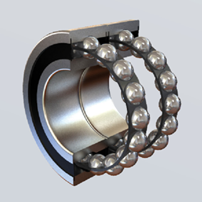
12. Thrust Bearings
Duplexed back to back installation of deep groove ball bearings provides high stiffness and allows for increased thrust loads, rotational speed and repeatability.
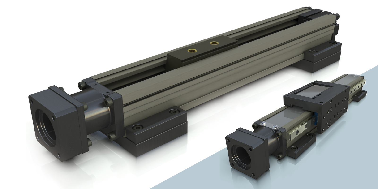
ML Series Linear Actuators
ML Advantage
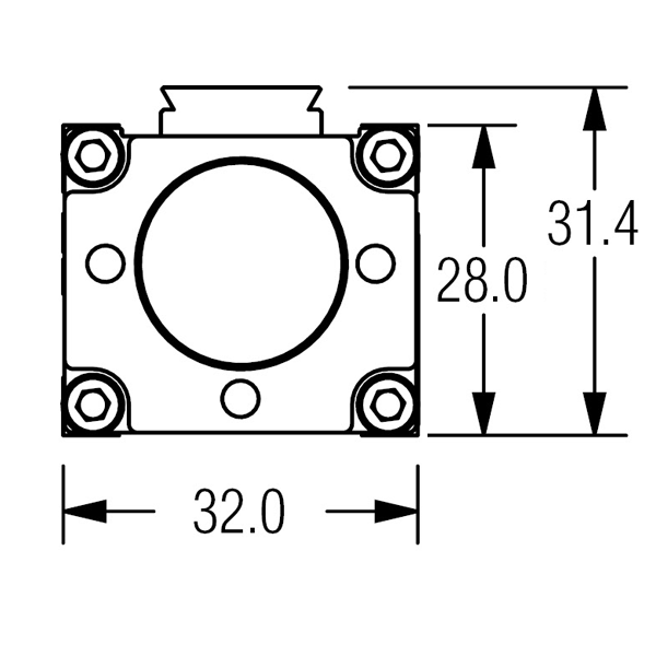
- Small, Compact Profile - 28 x 32 mm
- Patent Pending SIMO® Process Ensures precision mounting, accurate installation and lightweight composition.
- Lead Screw Driven - High accuracy and precise repeatability
- Multi-Axis Configurations
- Long Travel Lengths - Up to 650 mm
MLC Series Motor Mount Only
Specially designed motor mounts and couplings for easy mounting and extended life
MLD Series Hand Driven (Shaft or Knob)
Adjustable hand operated knob and brake for precision control.
MLB Series Motor Driven
Pre-mounted stepper or servo motors.
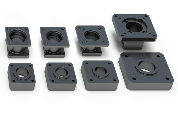
Accessories
Motor Mount Assembly
Riser Plates & Side Motor Mount Cover
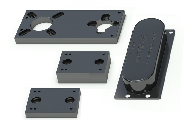
Seal Strip & Sensors
Stepper & Servo Motors
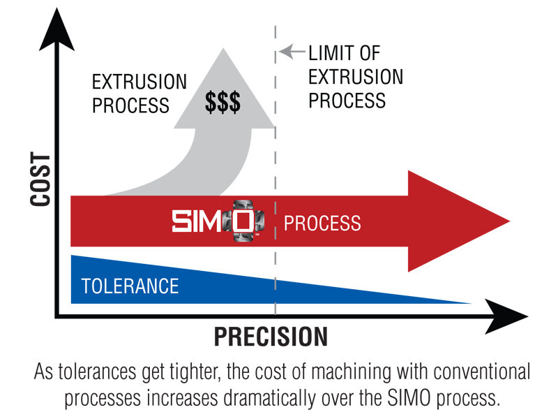
SIMO - Simultaneous Integral Milling Operation
Machine tools are built on precision machined castings or
weldments.
Why shouldn’t your actuator be built the
same?
PBC Linear has revolutionized traditional machining with the patent pending SIMO™
(Simultaneous Integral Milling Operation).
SIMO process uses synchronized
cutters, eliminating built-in extrusion variances by machining all critical edges
concurrently in one pass. This ensures tight tolerances, limited variance and a
remarkably straight and repeatable surface at negligible additional cost!
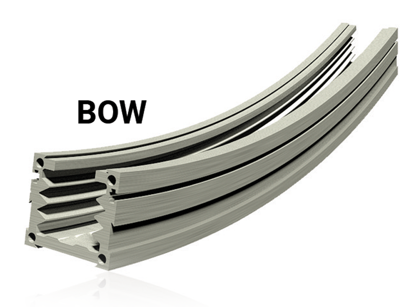
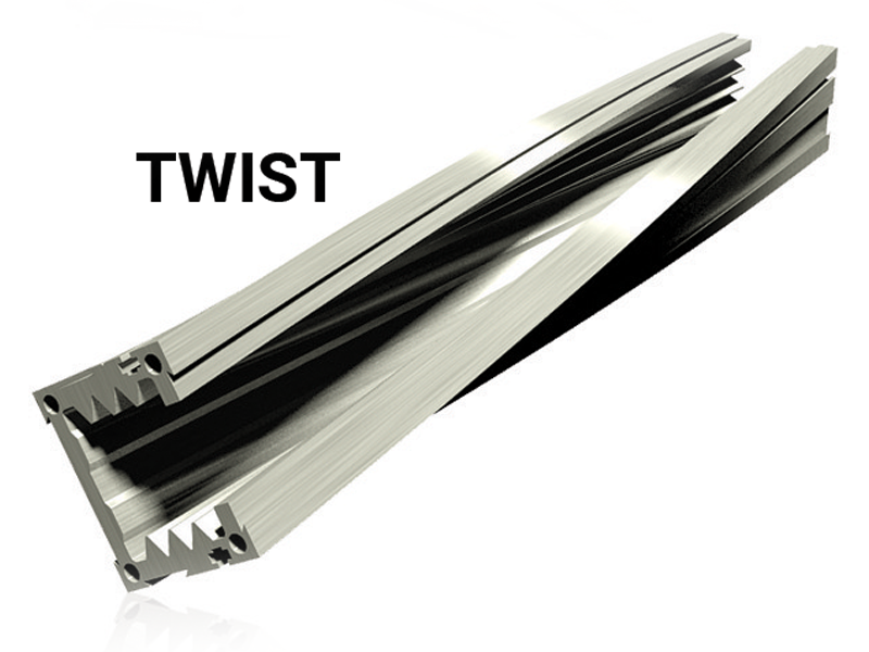
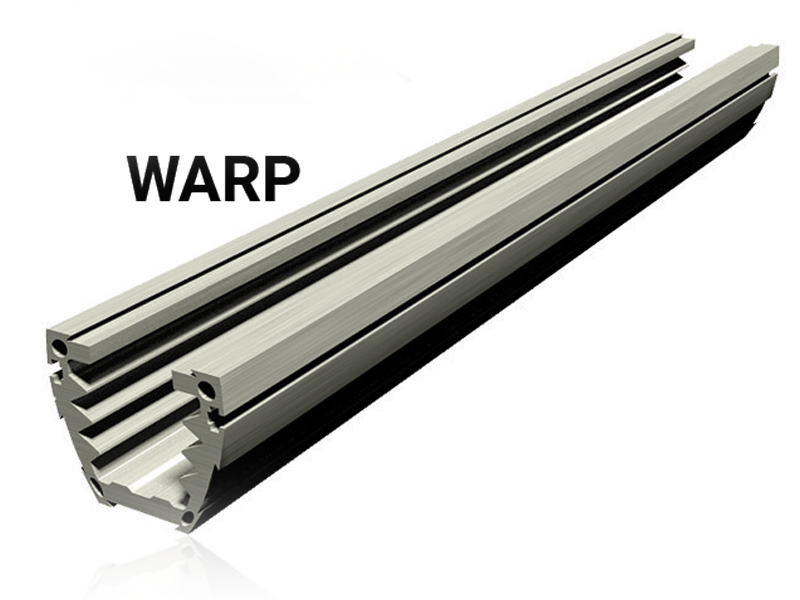
Profile View
Typical Aluminum Extrusion Issues
The typical aluminum extrusion process produces a natural bow, twist and variance. Costly straightening and aligning is traditionally used to combat this variance, resulting in a semi-straight aluminum extrusion that drives the cost up.
- Patent Pending Machining Process
- High Precision Mounting Surfaces
- Tight Tolerances ± 0.025mm (0.001 in)
ML Advantage
Using the machine tooled precision and rigid surfaces sustained by the SIMO™ process, the ML’s bridge gantry design can support 1 or 2 linear guides on the sides of the ML.
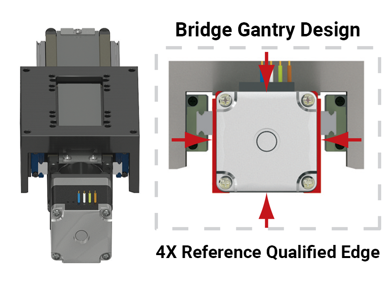
These supports work together to increase load capacities and sustain stability while utilizing recirculating caged-ball technology to provide smooth and quiet linear motion guidance.
Technical Data
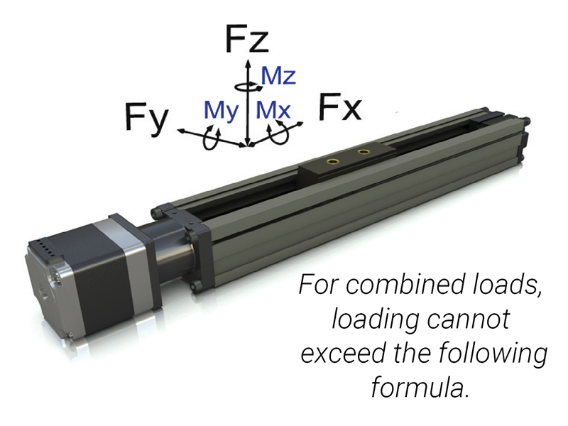
\( \displaystyle \frac{Fy_{A}}{Fy} + \frac{Fz_A}{Fz} + \frac{Mx_A}{Mx} + \frac{My_A}{My} + \frac{Mz_A}{Mz} \leq 1 \)
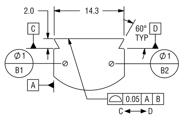
Center of Gravity for Moment Calculations
External Dovetail Easy Sketch
| ML SERIES - Carriage only | |||||
|---|---|---|---|---|---|
| Size | mm | 28 x 32 | in | 1.10 x 1.26 | |
| MAX Load - Lite Preload - anti-backlash - Standard |
Fx | N | 44 267 |
lbf | 10 60 |
| Fy | 107 | 24 | |||
| Fz | 178 | 40 | |||
| MAX Moments | Mx | Nm | 1.4 | lbf-in | 12.4 |
| My | 1.4 | 12.4 | |||
| Mz | 1.4 | 12.4 | |||
| Bending Moment of Inertia (second moment of area) |
Iy | cm4 | 2.4 | in4 | 0.058 |
| Iz | 4.4 | 0.106 | |||
| Base Weight without Motor | Kg | 0.060 | lbf | 0.130 | |
| Add for 100 mm of stroke | 0.150 | 0.340 | |||
| Total Carriage Mass | 0.020 | 0.044 | |||
| Total Carriage Mass & Top Plate | 0.059 | 0.130 | |||
| Coefficient of Friction | 0.19 | ||||
| MAX Speed | m/s | 1 | in/s | 75 | |
| MAX Stroke Length | mm | 650 | in | 25.6 | |
| MIN Stroke Length | 5 | 0.200 | |||
| Nominal Screw Diameter | 10.0 | 0.375 | |||
| Max RPM | 3000 | ||||
| No Load Torque Nut | - Lite Preload - anti-backlash | Nm | 0.0565 | lbf-in | 0.500 |
| - Normal Preload - anti-backlash | 0.1060 | 0.940 | |||
| - Standard | 0.0070 | 0.062 | |||
| Linear Guide Supports | - Single Linear Guide | Nm | 0.017 | lbf-in | 0.15 |
| - Dual Linear Guides | 0.034 | 0.30 | |||
| Seal Strip | - with Seal Strip | Nm | 0.028 | lbf-in | 0.25 |
| - without Seal Strip | 0 | 0 | |||
| Screw Lead Accuracy* | mm/mm | 0.0006 | in/in | 0.0006 | |
| Normal Operating Temperature (Wider ranges available) |
MIN | °C | 18 | °F | 32 |
| MAX | 98 | 176 | |||
*Higher accuracies are available to 0.0001 mm/mm (in/in). Contact manufacturer for details. Specifications are subject to change without notice.
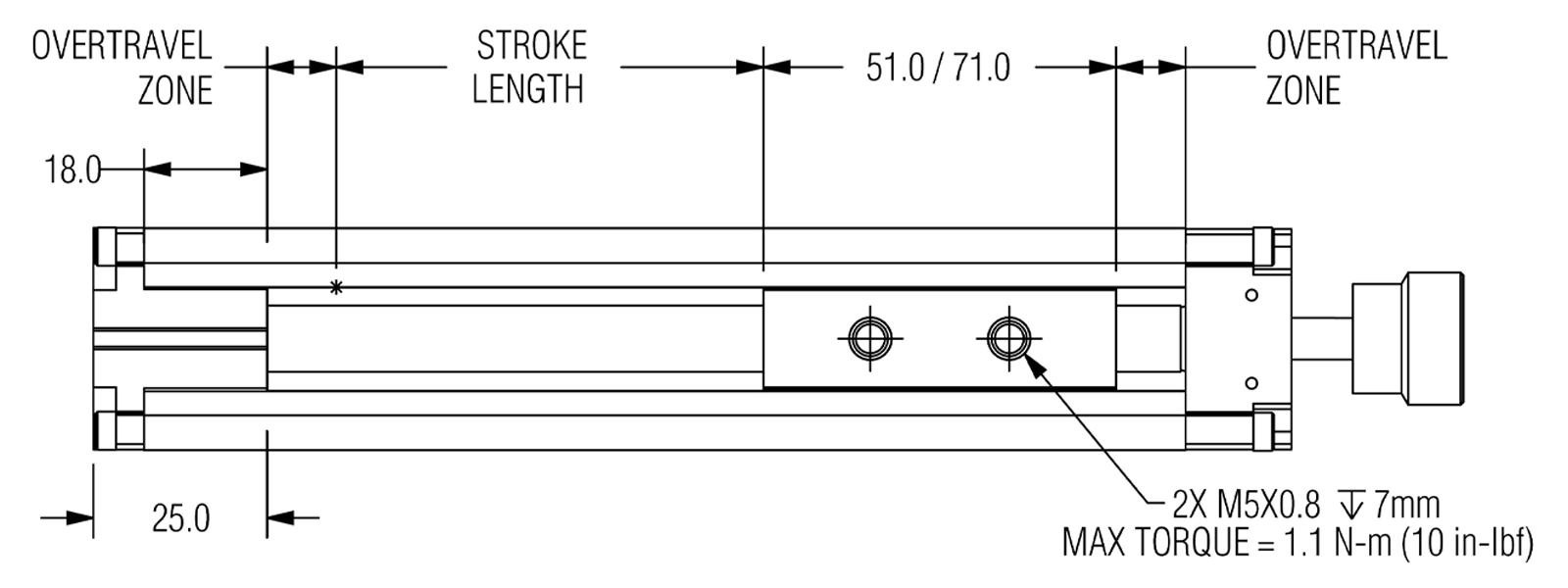
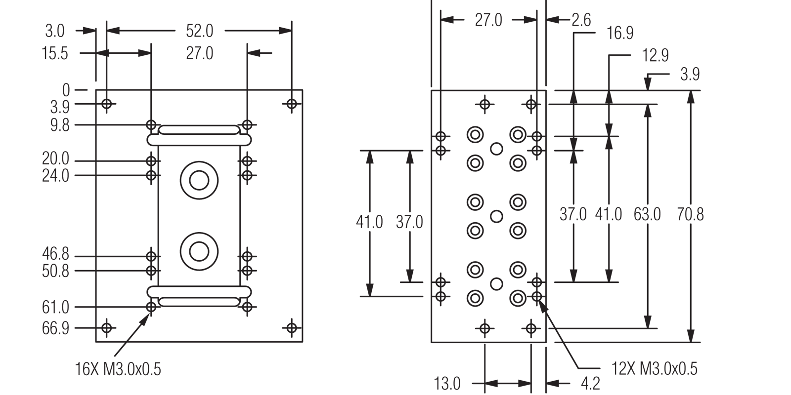
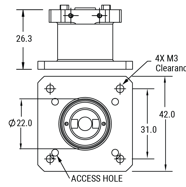
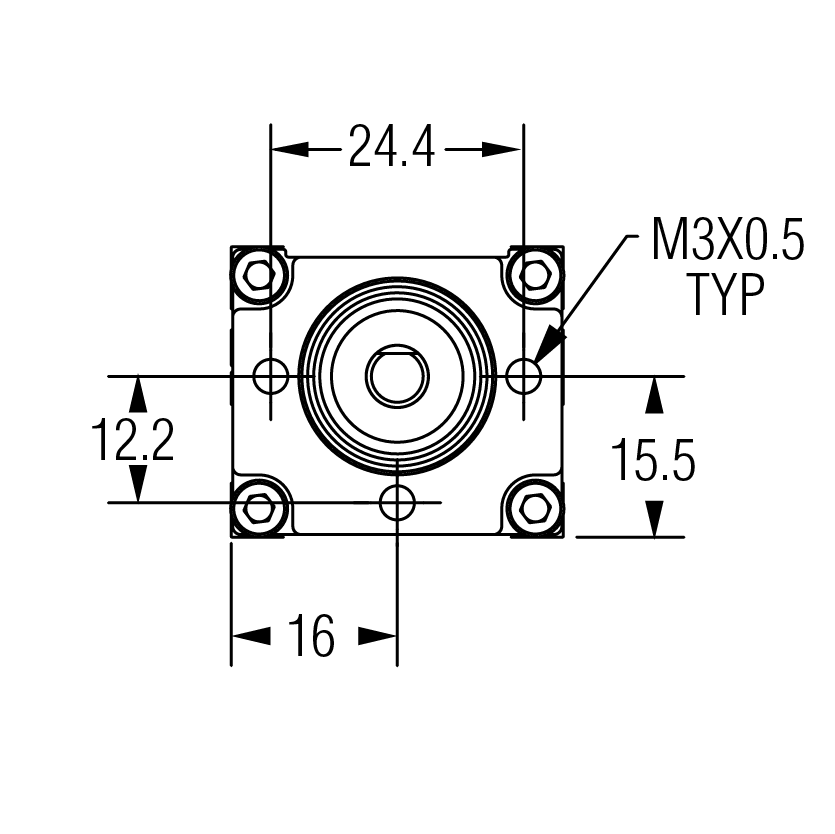
Dimensional Data
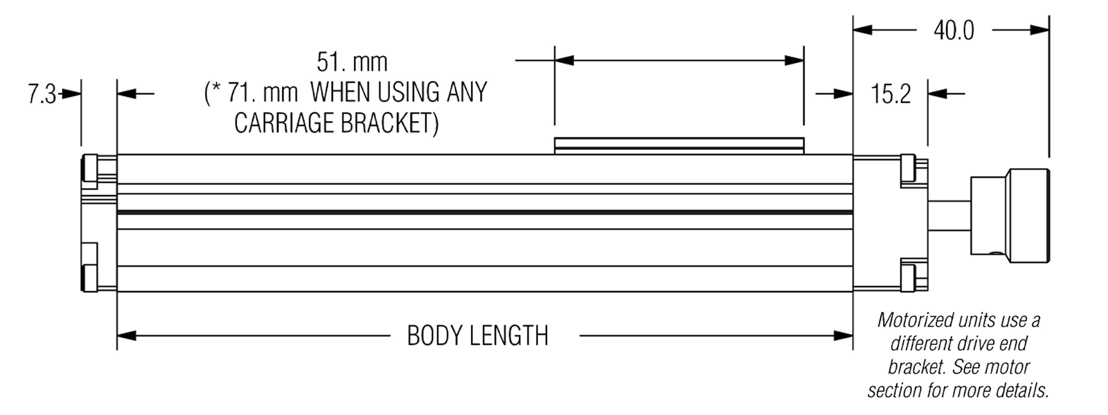
NOTE: BODY LENGTH = STROKE + *CARRIAGE LENGTH + (2X OVER TRAVEL) + 18mm
CARRIAGE WITH DOVETAIL
RECOMMENDED
OVERTRAVEL PER SIDE
Knob or Hand Crank = 5mm
Stepper Motor = 10mm
Servo Motor =
20mm
How to Calculate Body Length
- Enter 19 mm
- Select (5, 10 or 20 mm) for overtravel on idle end (See recommended overtravel above.)
- Specify stroke length in mm
- Select (51 or 71 mm) for carriage length
- Select (5, 10 or 20 mm) for overtravel on idle end (See recommended overtravel above.)
- Add amounts together and enter SUBTOTAL
- Enter TOTAL BODY LENGTH (Round to nearest 10 mm)
- When ORDERING enter TOTAL BODY LENGTH in BODY LENGTH column.
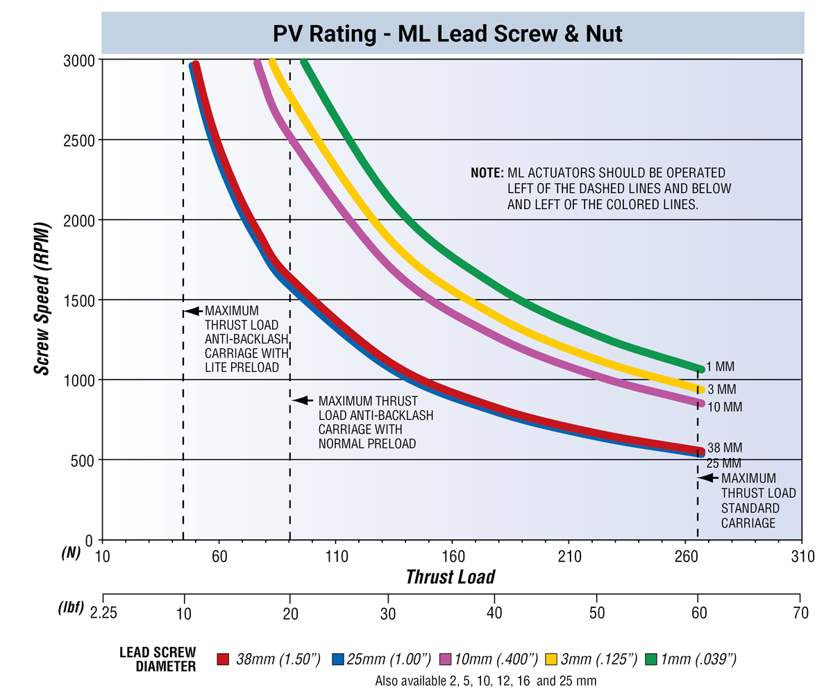
Performance Data
The load rating and system speed must both be accounted for when sizing a lead screw
system. The nut threads and screw threads form a plane bearing system.
The
PV limit of a polymer material is the point at which friction-generated heat can no
longer be expelled at a rate to prevent the material from overheating. Such
overheating while under stress can cause permanent deformation of the material.
Ignoring how the system’s speed and loading relate to the nut material’s PV rating
can lead to dramatically shorter thread life. The primary modes of failure for lead
screw systems are wear and PV. By staying within the PV envelope of the screw and
nut, one can ensure long life of the nut without premature wear.
Torque to Raise Load
\( \displaystyle T_L \ (\text{Nm}) = \frac{\text{Load (N)} \cdot \text{Lead (mm)}}{2\pi \cdot \text{Efficiency} \cdot 1000} \)
\( \displaystyle T_L \ (\text{in-lbf}) = \frac{\text{Load (lbf)} \cdot \text{Lead (in)}}{2\pi \cdot \text{Efficiency}} \)
| Performance Characteristics |
Lead Screw mm (in) | |||||
|---|---|---|---|---|---|---|
| 38 (1.50) | 25 (1.00) | 10 (.400) | 3 (.125) | 1 (.039) | ||
| Max, Travel Speed | mm/s (in/s) | 1905 (75) | 1270 (50) | 508 (20) | 159 (6.25) | 50 (1.95) |
| Screw Diameter | mm (in) | 10 (0.375) | 10 (0.375) | 10 (0.375) | 10 (0.375) | 10 (0.375) |
| Screw Efficiency | (See formula to right) | 81% | 82% | 77% | 57% | 26% |
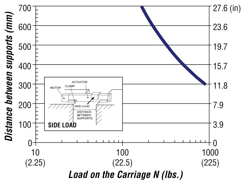
Distance Between Supports
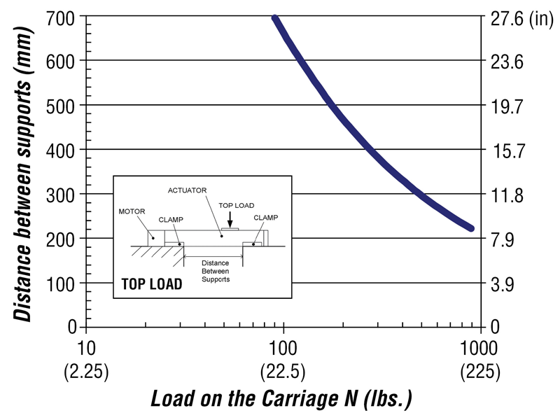
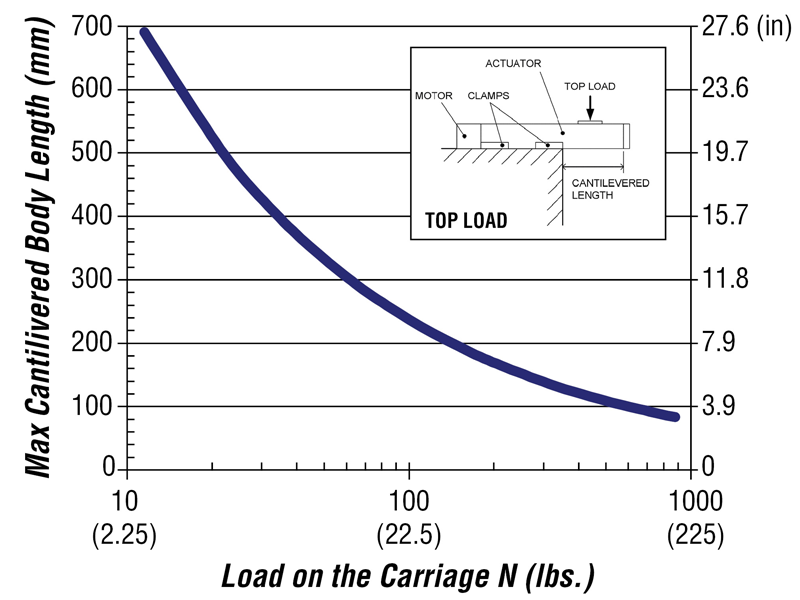
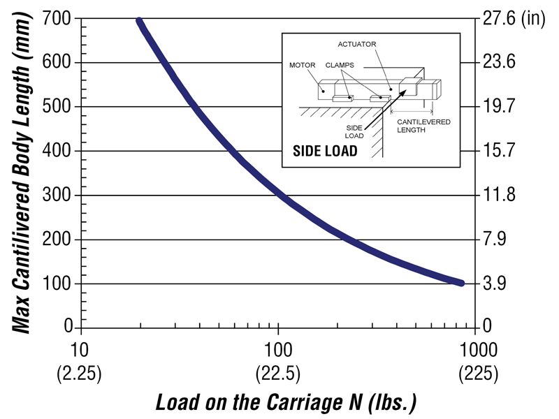
Maximum Cantilevered Length
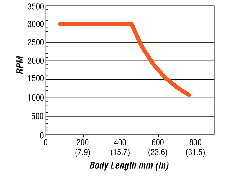
Maximum Travel Speeds

80% of Critical Speed
Ordering Options
ML Options Provide You with a Perfect Fit System
Lead Screw
- Large 10 mm diameter lead screw reduces whip and increases column strength allowing longer stroke lengths
- Lead options*: 1, 2, 5, 10, 12, 16, and 25 mm. 3 mm (0.125’’), 10 mm (0.400’’),
25 mm (1’’), 38 (1.5’’)
*Contact manufacturer for other available sizes - Nominal Lead Screw Diameter = 10 mm (0.375”)
- Screw Inertia = 4.169 x 10⁻⁶ kg-m²/m (1.5 x 10⁻⁵ oz.-in.sec.²/in.)
- Lead Screw Length = Body Length + 32.27 mm
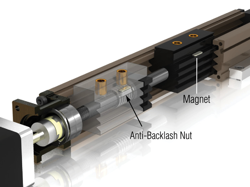
Nut Type
- Standard nut Fx=262 N (60 lb) or anti-backlash nut Fx=44 N (10 lb)
- Optional anti-backlash nut - ideal in applications requiring high bi-directional accuracy and repeatability
- Magnet is built-in for use with home and position sensors
- Anti-Backlash light pre-load Nut limits Fx linear thrust force capacity
Seal Strip with Carriage Bracket
- Ultra wear-resistant molybdenum disulfide impregnated nylon
- Prevents debris from entering or exiting actuator
- Seal strip is 725mm in length (Can be cut shorter using sharp pair of scissors.)


ML Actuator Build, Mount, Use
Build Your ML Actuator
Step 1: Configure Your System Axis
- Determine if you need an external linear guide for support
- Calculate the body length
Step 2: Choose the Drive Method
- Motor pre-mounted and tested by PBC Linear? \(\Rightarrow\) MLB
- Ready to mount your own motor? \(\Rightarrow\) MLC
- Driven by hand? \(\Rightarrow\) MLD
Step 3: Choose How to Mount Axis
- Choose dovetail clamps or riser plates (Use riser plates with NEMA 17 and 23 motors)
Step 4: Choose End of Travel and Home Limit Switches/Sensors
- Determine mounting type/location (bracket type)
- Choose from list of compatible sensors
Repeat 1-5 for Each Axis
Step 5: Order Your System 1-800-962-8979 or 1-815-389-5600
Questions?
Call an Application Engineer
1-888-777-0556
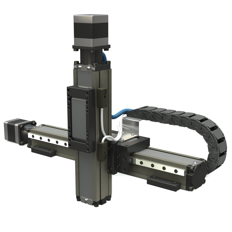
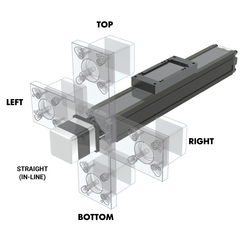
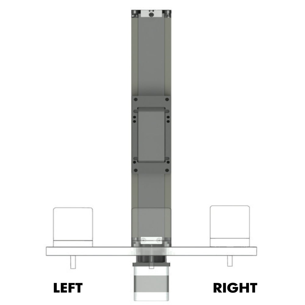
Multi-Axis Mounting
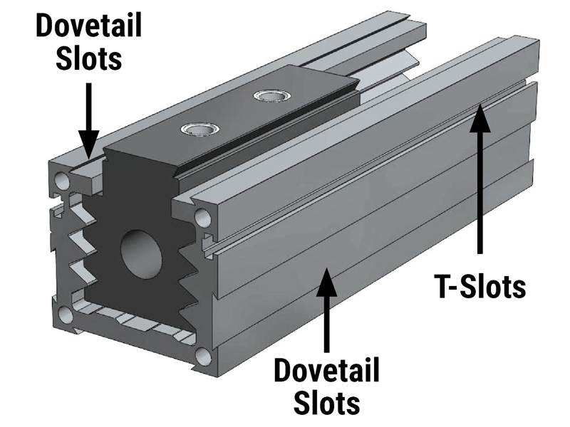
ML actuators are designed to perform well in X Y and other Cartesian arrangements.
The actuator body forms a strong beam with higher moment loading capacity. Special
dovetail slots on all sides allow the actuators to be mounted on their bottom
surface or on either side.
Carriage brackets and special wedge mounting
clamps allow for precise and rigid mounting arrangements. Linear guides can be
installed on one or both sides of the actuator with one or two runner blocks on each
rail for greater rigidity in gantry applications.
Multi-axis gantries can
also be created by combining the ML with other actuators such as the PL or MT
Series.
X Y
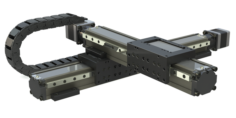
X Z
X Y Z
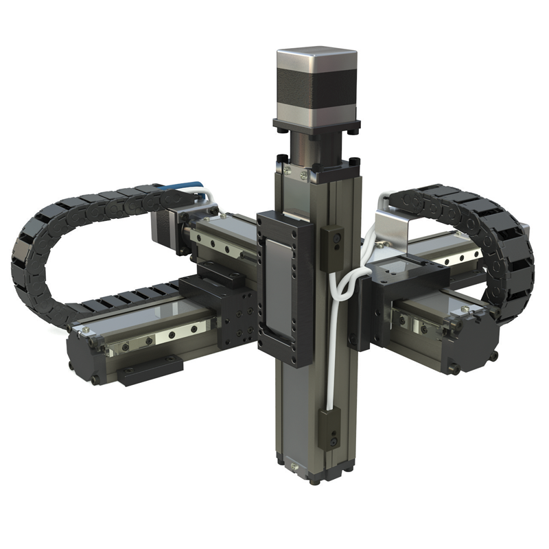
Superior Multi-Axis Mounting for Compact Applications
- Medical
- Biotech
- Instrument Automation
- Packaging
- Pick & Place
- Semi-conductor
- Scanning
MULTI-AXIS MTB Series with MLB
ML Applications


The ML miniature actuator has a combination of compactness and (60 lbf) 265 N pound thrust power gives this actuator an edge for automation applications where space is critical. Plus, the SIMO® machined rail surface and zero backlash lead screw assembly ensures accuracy and precision for syringe pumps and optical control applications.
Linear Guide Supports
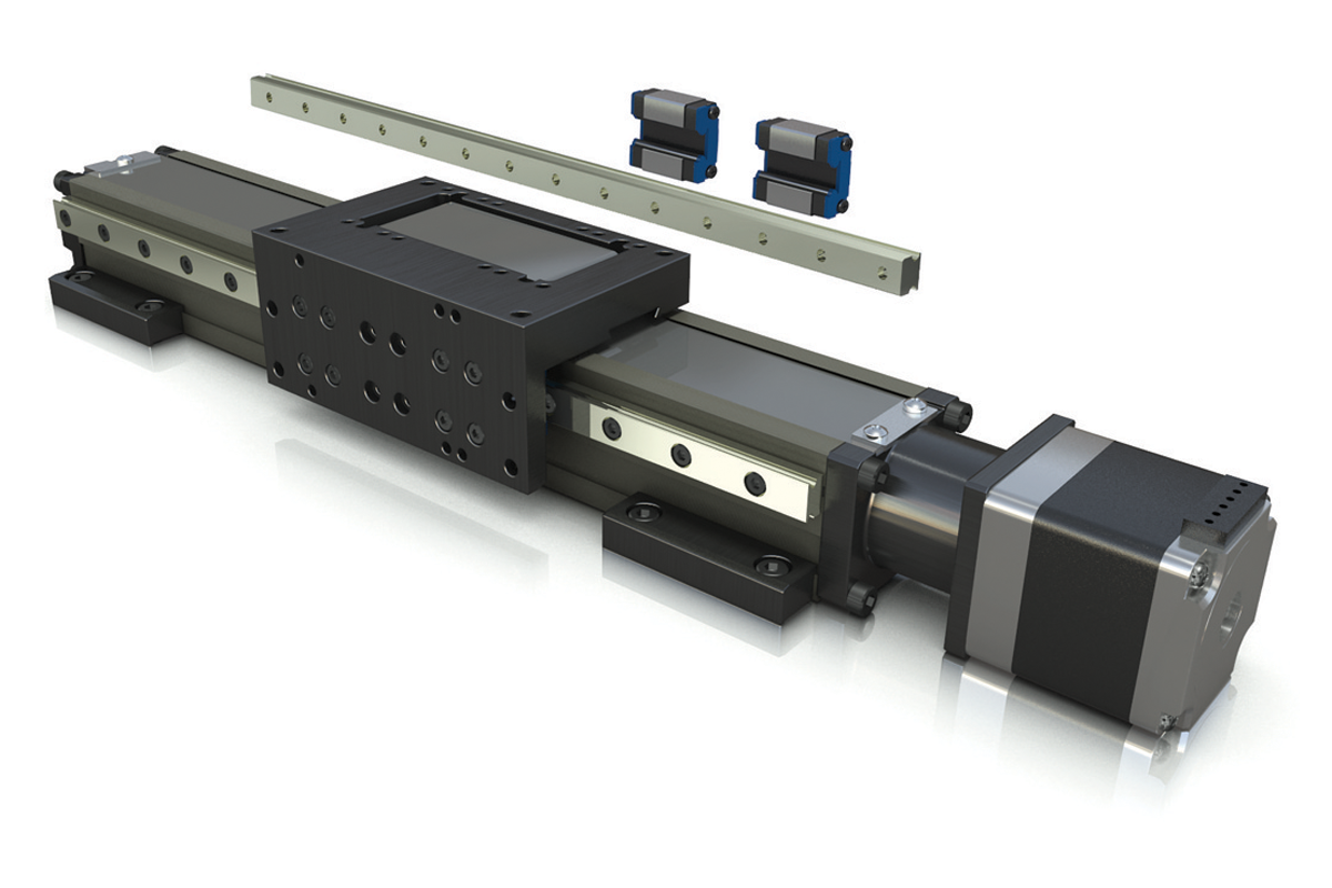
The ML series features the unique option for dual external linear guides (also available with single linear guide option). These re-circulating ball runner blocks assure high speed precision as well as enhanced load capacities and stability.
Support Options to Create Variable
Levels of Performance
| Technical Data Linear Guide Supports |
(1) Single | (2) Dual | (1) Single | (2) Dual | ||||||||
|---|---|---|---|---|---|---|---|---|---|---|---|---|
| # of runner blocks on each guide | # of runner blocks on each guide | |||||||||||
| 1 | 2 | 1 | 2 | 1 | 2 | 1 | 2 | |||||
| MAX Load | Anti-Backlash Lite Preload |
Fx | N | 44 | 44 | 44 | 44 | lbf | 10 | 10 | 10 | 10 |
| Anti-Backlash Normal Preload |
89 | 89 | 89 | 89 | 20 | 20 | 20 | 20 | ||||
| Standard Nut | 267 | 267 | 267 | 267 | 60 | 60 | 60 | 60 | ||||
| Fy | 180 | 250 | 445 | 890 | 40 | 56 | 100 | 200 | ||||
| Fz | 267 | 356 | 445 | 890 | 60 | 80 | 100 | 200 | ||||
| MAX Moments | Mx | Nm | 1.8 | 3.6 | 8.6 | 18 | lbf-in | 16 | 32 | 76 | 160 | |
| My | 1.8 | 5.0 | 3.6 | 10 | 16 | 44 | 32 | 88 | ||||
| Mz | 1.8 | 5.0 | 3.6 | 10 | 16 | 44 | 32 | 88 | ||||
| Bending Moment of Inertia (Second Moment of Area) |
Iy | cm4 | 2.4 | 2.4 | 2.4 | 2.4 | in4 | 0.058 | 0.058 | 0.058 | 0.058 | |
| Iz | 4.4 | 4.4 | 4.4 | 4.4 | 0.106 | 0.106 | 0.106 | 0.106 | ||||
| Base Weight without Motor | Kg | 0.127 | 0.136 | 0.195 | 0.205 | lbf | 0.280 | 0.300 | 0.430 | 0.450 | ||
| Add for 100 mm of Stroke | 0.180 | 0.180 | 0.210 | 0.210 | 0.400 | 0.400 | 0.460 | 0.460 | ||||
| Total Carriage Mass | 0.109 | 0.117 | 0.159 | 0.175 | lbm | 0.240 | 0.257 | 0.350 | 0.385 | |||
| Coefficent of Friction | 0.190 | 0.010 | 0.190 | 0.010 | ||||||||
Notes:
- Moment arms for calculating moments should be measured from the center of the extrusion
- Limit switches must be used in order to prevent the carriage from contacting the actuator end blocks, resulting in damage
- Servo drive system, recommended overtravel of 20 mm
- Stepper motors or manual hand cranks system, add 5 mm of over-travel
Dimensional Data
Single Linear Guide Supports
INCLUDES:
(1) rail, (1) runner block & aluminum alloy L
shaped carriage bracket
- or -
(1) rail, (2) runner blocks & aluminum
alloy L shaped carriage bracket
Dual Linear Guide Supports
INCLUDES:
(2) rails, (1) runner block & aluminum alloy U
shaped carriage bracket
- or -
(2) rails, (2) runner blocks & aluminum
alloy U shaped carriage bracket
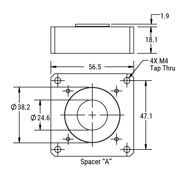
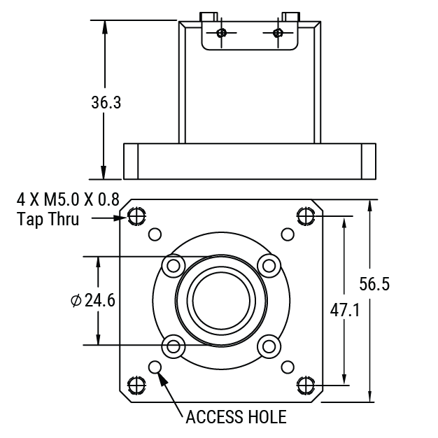
MLC Series
Motor Mount Only
PBC Linear stepper motors do not require a spacer due to the shorter shaft length. A spacer is required for any other manufacturer’s motor. The spacer compensates for several dimensions which commonly vary amongst motor manufacturers (shaft diameter, shaft length, pilot diameter, pilot depth, bolt hole diameter, bolt type).
- Includes motor mount with coupling
- Includes motor spacer (if required)
- Precision machined body
- Small, compact design
- Smooth and quiet operation
- High acceleration, speed and rigidity
MLC Ordering Guide
| Series | Linear Guide Supports* | Leads | Nut Type | Seal Strip | # of Carriages | Body Length | Motor Location | Motor Frame Size | Shaft OD | Coupling Material | Spacer Config | Config | |||
| MLC028D | - | X | XX | X | X | X | - | XXXX | - | X | X | X | X | X | 0 |
SeriesML Series with motor mount 28 x 32 mm Linear Guide Supports*0 = No External Rail 1 = (1) Rail, (1) Runner Block - XY-2 Brkt (R) 2 = (1) Rail, (2) Runner Blocks - XY-2 Brkt (R) 3 = (2) Rail, (1) Runner Block - XY-3 Brkt 4 = (2) Rail, (2) Runner Blocks - XY-3 Brkt 5 = (1) Rail, (1) Runner Block - XY-2 Brkt (L) 6 = (1) Rail, (2) Runner Blocks - XY-2 Brkt (L) 7 = No Seal Strip - XY-1 Brkt *(L) = Left (R) = Right LeadsAH = 1 mm AG = 2 mm AX = 5 mm AJ = 10 mm BD = 12 mm AF = 16 mm AW = 25 mm Nut Type2 = Standard Nut 4 = Anti-backlash (light preload) Seal Strip0 = None 1 = With Seal Strip & XY Bracket # of Carriages1 = 1 Carriage 2 = 2 Carriages 3 = 3 Carriages 4 = 4 Carriages Note: Contact manufacturer before ordering multiple carriages. Body LengthExamples: 0090 = 90 mm 0250 = 250 mm Motor LocationS = Straight (in-line) L = Left R = Right B = Bottom T = Top At time of order, customer must declare their pilot diameter, shaft length and mounting hole pattern of the matching motor so that the proper spacer can be included. Motor Frame SizeA = NEMA 8 (20mm) B = NEMA 11 (28mm) C = NEMA 14 (35mm) E = Metric 40 F = NEMA 17 (42mm) G = NEMA 23 (56/58mm) At time of order, customer must declare their pilot diameter, shaft length and mounting hole pattern of the matching motor so that the proper spacer can be included. Shaft ODA = 3 mm B = 0.125 in C = 4 mm D = 0.1875 in E = 5 mm F = 6 mm G = 0.25 in H = 0.3125 in J = 8 mm At time of order, customer must declare their pilot diameter, shaft length and mounting hole pattern of the matching motor so that the proper spacer can be included. Coupling Material1 = Acetal At time of order, customer must declare their pilot diameter, shaft length and mounting hole pattern of the matching motor so that the proper spacer can be included. Spacer ConfigA = Standard At time of order, customer must declare their pilot diameter, shaft length and mounting hole pattern of the matching motor so that the proper spacer can be included. Config0 = Standard At time of order, customer must declare their pilot diameter, shaft length and mounting hole pattern of the matching motor so that the proper spacer can be included. |
NOTE: Not all combinations are possible. Contact manufacturer for available combinations. Body lengths are available in 1 mm increments up to 701 mm. Standard lengths are multiples of 10 mm. When possible round up to nearest multiple of 10 mm. NEMA 11 stepper motors typically do not have enough torque to drive the anti-backlash nuts. Customers are responsible for doing torque calculations to ensure the motor is properly sized. Specifications are subject to change without notice.
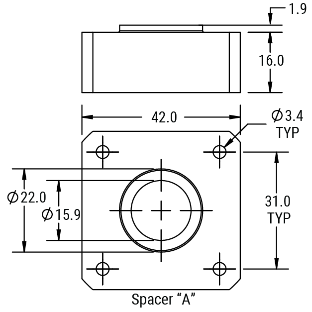
Motor Mount Assembly
Assembly Dimensions
Spacer A
Motor Frame Size
Assembly Dimensions
Spacer A
Motor Frame Size
Assembly Dimensions
Spacer A
Motor Frame Size
Assembly Dimensions
Spacer A
Motor Frame Size
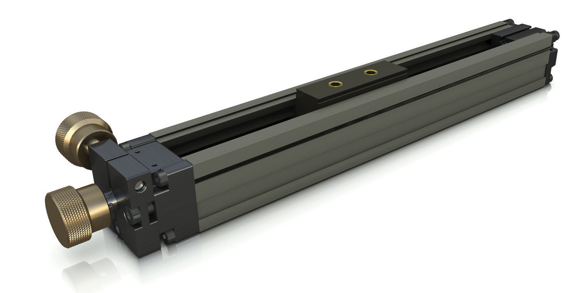
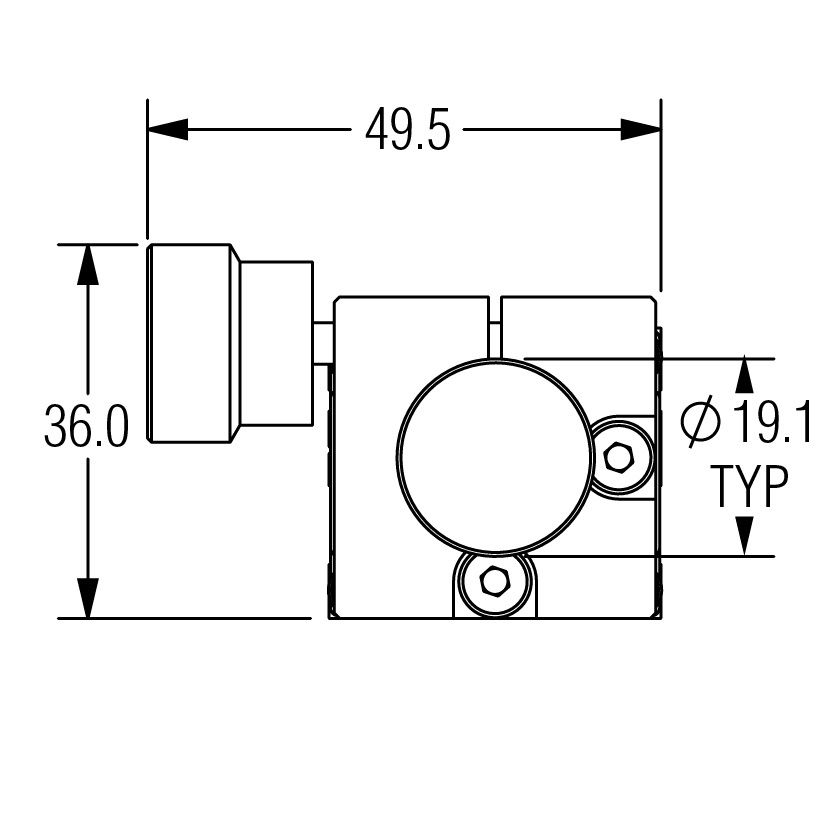
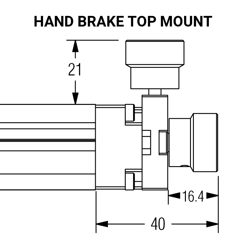
MLD Series
Hand Driven shaft or knob
- Perfect for hand-operated precision control
- Manual brake optional
- Textured knob for both positioning and braking
- Precision machined body
- Small, compact design
- Great repeatability
MLD Ordering Guide
| Series | Linear Guide Supports* | Leads | Nut Type | Seal Strip | # of Carriages | Body Length | (Drive) Knob | Brake | Configuration | |||
| MLD028D | - | X | XX | X | X | X | - | XXXX | - | X | X | 0 |
SeriesML Series with knob/drive lead screw driven 28 x 32 mm Linear Guide Supports*0 = No External Rail 1 = (1) Rail, (1) Runner Block - XY-2 Brkt (R) 2 = (1) Rail, (2) Runner Blocks - XY-2 Brkt (R) 3 = (2) Rail, (1) Runner Block - XY-3 Brkt 4 = (2) Rail, (2) Runner Blocks - XY-3 Brkt 5 = (1) Rail, (1) Runner Block - XY-2 Brkt (L) 6 = (1) Rail, (2) Runner Blocks - XY-2 Brkt (L) 7 = No Seal Strip - XY-1 Brkt *(L) = Left (R) = Right LeadsAH = 1 mm AG = 2 mm AX = 5 mm AJ = 10 mm BD = 12 mm AF = 16 mm AW = 25 mm Nut Type2 = Standard Nut 4 = Anti-backlash (light preload) Seal Strip0 = None 1 = With Seal Strip & XY Bracket # of Carriages1 = 1 Carriage 2 = 2 Carriages 3 = 3 Carriages 4 = 4 Carriages Note: Contact manufacturer before ordering multiple carriages. Body LengthExamples: 0090 = 90 mm 0250 = 250 mm (Drive) Knob0 = No - shaft only 1 = Yes - with knob Brake0 = No 1 = Yes (at drive end) Configuration0 = Standard |
NOTE: Not all combinations are possible. Contact manufacturer for available combinations. Body lengths are available in 1mm increments up to 701mm. Standard lengths are multiples of 10mm. When possible round up to nearest multiple of 10mm. Specifications are subject to change without notice.
Dimensional Data
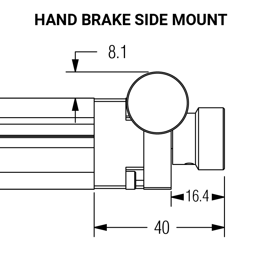
NOTE: Brake installed on side as default and can easily be changed to the top by the customer.
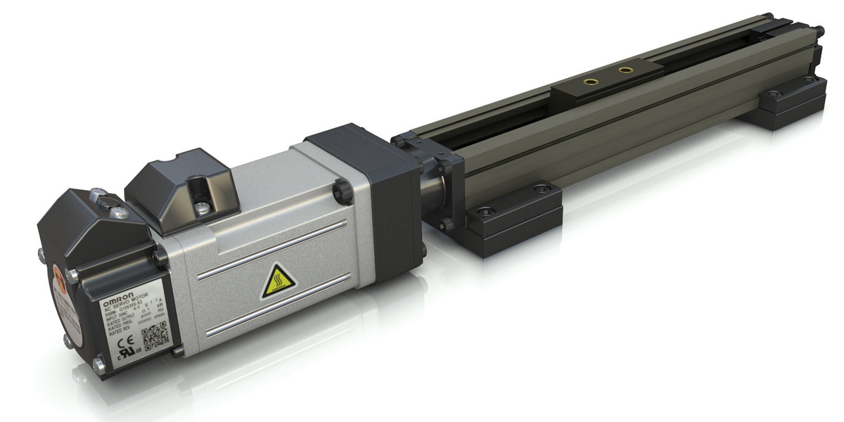
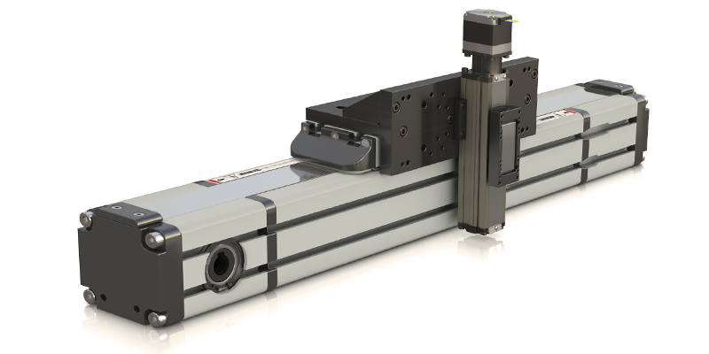
MLB Series
Integrated Motor
- Full stock of open and closed loop stepper motors and servo motors
- Available in NEMA 11,14,17, 23
- Precision machined body
- Small compact design
- High acceleration, speed, and rigidity
- Pre-engineered and assembled for easy installation
MLB Ordering Guide
| Series | Linear Guide Supports* | Leads | Nut Type | Seal Strip | # of Carriages | Body Length | Motor Location | Motor Make | Motor Frame Size | Motor Power | Motor Feature | Configuration | |||
| MLB028D | - | X | XX | X | X | X | - | XXXX | - | X | X | X | X | XX | 0 |
SeriesML Series with knob/drive lead screw driven 28 x 32 mm Linear Guide Supports*0 = No External Rail 1 = (1) Rail, (1) Runner Block - XY-2 Brkt (R) 2 = (1) Rail, (2) Runner Blocks - XY-2 Brkt (R) 3 = (2) Rail, (1) Runner Block - XY-3 Brkt 4 = (2) Rail, (2) Runner Blocks - XY-3 Brkt 5 = (1) Rail, (1) Runner Block - XY-2 Brkt (L) 6 = (1) Rail, (2) Runner Blocks - XY-2 Brkt (L) 7 = No Seal Strip - XY-1 Brkt *(L) = Left (R) = Right LeadsAH = 1 mm AG = 2 mm AX = 5 mm AJ = 10 mm BD = 12 mm AF = 16 mm AW = 25 mm Nut Type2 = Standard Nut 4 = Anti-backlash (light preload) 6 = Anti-backlash (normal preload) Seal Strip0 = None 1 = With Seal Strip & XY Bracket # of Carriages1 = 1 Carriage 2 = 2 Carriages 3 = 3 Carriages 4 = 4 Carriages Note: Contact manufacturer before ordering multiple carriages. Body LengthExamples: 0090 = 90 mm 0250 = 250 mm Motor LocationS = Straight L = Left R = Right B = Bottom T = Top Motor Make1 = PBC Linear™ Open loop stepper motor Motor Frame SizeB = NEMA 11 (28mm) C = NEMA 14 (35mm) F = NEMA 17 (42mm) G = NEMA 23 (56mm) Motor PowerB = Single Stack C = Double Stack* D = Triple Stack *not available with NEMA 14 Motor Feature00 = Hybrid wiring (8 wires), flying leads, no encoders [hybrid wiring can be bi-polar or uni-polar] Configuration0 = Standard |
NOTE: Not all combinations are possible. Contact manufacturer for available combinations. Body lengths are available in 1 mm increments up to 701 mm. Standard lengths are multiples of 10 mm. When possible round up to nearest multiple of 10 mm. Longer lead times apply to non-standard lengths. NEMA 11 stepper motors typically do not have enough torque to drive the anti-backlash nuts. Customers are responsible for doing torque calculations to ensure the motor is properly sized. Specifications are subject to change without notice.
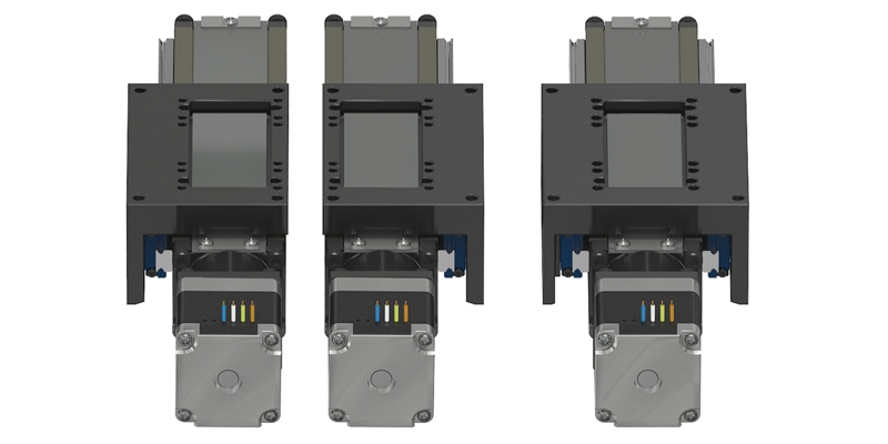
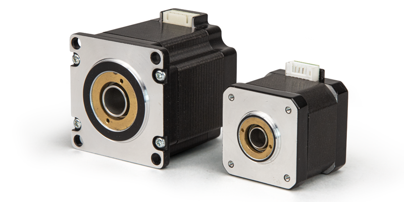
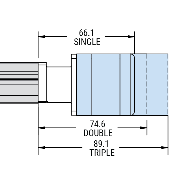
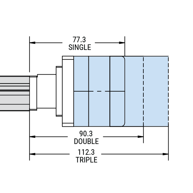
Stepper Motor Options
PBC Linear brand stepper motors are designed to reduce length in the ML actuator. Single, double and triple stack motors are available in each size.

Motor Locations
Using universal motor mounts, PBC Linear’s ML series mini-actuators give our customers the freedom for limitless mounting options. Straight (in-line), top, bottom or side motor mounting allows the ML series to fit seamlessly into any specified application.
Wiring Harnesses
Plug Connector included with all Stepper Motor Equipped MLB Series Actuators
NEMA 11 Series

NEMA 14 Series
NEMA 17 Series

NEMA 23 Series

Stepper Motor


NEMA 11 (28mm)
NEMA 14 (35mm)
NEMA 17 (42mm)
NEMA 23 (56mm)
| NEMA Rating |
Motor Power |
Current per Phase |
Holding Torque | Detent Torque | Rotor Inertia | Length mm (in) |
Weights kg (lb) |
Model P/N# |
|||
|---|---|---|---|---|---|---|---|---|---|---|---|
| A | mN · m | oz-in | mN · m | oz-in | g-cm2 | oz-in2 | |||||
| NEMA 11 | Single | 1 | 50 | 7.08 | 5 | 0.71 | 9 | 0.05 | 31 (1.21) | 0.10 (0.22) | 6200297 |
| NEMA 11 | Double | 0.67 | 90 | 12.75 | 6 | 0.85 | 12 | 0.07 | 40 (1.56) | 0.15 (0.33) | 6200298 |
| NEMA 11 | Triple | 1 | 100 | 14.16 | 8 | 1.13 | 18 | 0.10 | 51 (2.01) | 0.20 (0.44) | 6200299 |
| NEMA 14 | Single | 0.40 | 60 | 8.5 | 10 | 1.42 | 12 | 0.07 | 26 (1.01) | 0.15 (0.33) | 6200300 |
| NEMA 14 | Triple | 0.85 | 100 | 14.16 | 15 | 2.12 | 20 | 0.11 | 37 (1.44) | 0.21 (0.46) | 6200302 |
| NEMA 17 | Single | 1.50 | 360 | 50.99 | 15 | 2.12 | 57 | 0.31 | 39.8 (1.57) | 0.28 (0.62) | 6200303 |
| NEMA 17 | Double | 1.50 | 490 | 69.41 | 25 | 3.54 | 82 | 0.45 | 48.3 (1.90) | 0.36 (0.79) | 6200304 |
| NEMA 17 | Triple | 1.50 | 630 | 89.24 | 30 | 4.25 | 123 | 0.68 | 62.8 (2.47) | 0.60 (1.32) | 6200305 |
| NEMA 23 | Single | 1.50 | 500 | 70.82 | 22 | 3.12 | 135 | 0.74 | 41 (1.61) | 0.42 (0.93) | 6200306 |
| NEMA 23 | Double | 1.50 | 1000 | 141.64 | 40 | 5.66 | 260 | 1.43 | 54 (2.13) | 0.60 (1.32) | 6200307 |
| NEMA 23 | Triple | 1.40 | 1650 | 233.71 | 70 | 9.91 | 460 | 2.53 | 76 (2.99) | 1.00 (2.20) | 6200308 |
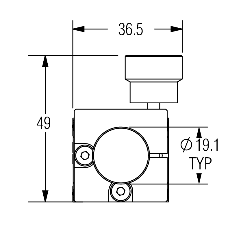
Motor Couplings
Motor Coupling (HUB & Disk)
- Compensates for motor and screw misalignment
- Electrically isolating
- Balanced design
HUB
DISK
For use with NEMA 11, 14, 17 Motors
| HUBS P/N # | Bore* | OD | HUB Length (LH) |
Coupling Length (L) |
Shaft Penetration |
Set Screw | Moment of Inertia (lb-in2) |
Moment of Inertia (kg x m2) |
|---|---|---|---|---|---|---|---|---|
| 6200129 | 3 mm | 12.7 mm | 5.6 mm | 15.9 mm | 5.6 mm | M3 | 0.0056” | 1.64E-06 |
| 6200286 | 5 mm | 12.7 mm | 5.6 mm | 15.9 mm | 5.6 mm | M3 | 0.0050” | 1.47E-06 |
| 6200350 | 6 mm | 12.7 mm | 5.6 mm | 15.9 mm | 5.6 mm | M3 | 0.0047” | 1.37E-06 |
| 6200113 | 0.125’’ | 0.500’’ | 0.222’’ | 0.625’’ | 0.222’’ | M3 | 0.0056” | 1.64E-06 |
| 6200349 | 0.250” | 0.500” | 0.222’’ | 0.625’’ | 0.222’’ | M3 | 0.0045” | 1.32E-06 |
For use with NEMA 23 Motors ONLY
| HUBS P/N # | Bore* | OD | HUB Length (LH) |
Coupling Length (L) |
Shaft Penetration |
Set Screw | Moment of Inertia (lb-in2) |
Moment of Inertia (kg x m2) |
|---|---|---|---|---|---|---|---|---|
| 6200130 | 4 mm | 19.1 mm | 7.6 mm | 22.2 mm | 7.6 mm | M3 | 0.0069 | 2.02E-06 |
| 6200131 | 5 mm | 19.1 mm | 7.6 mm | 22.2 mm | 7.6 mm | M3 | 0.0068 | 1.99E-06 |
| 6200132 | 6 mm | 19.1 mm | 7.6 mm | 22.2 mm | 7.6 mm | M3 | 0.0066 | 1.94E-06 |
| 6200133 | 8 mm | 19.1 mm | 7.6 mm | 22.2 mm | 7.6 mm | M3 | 0.0061 | 1.79E-06 |
| 6200114 | 0.1875” | 0.750” | 0.300” | 0.875” | 0.300” | M3 | 0.0068 | 1.99E-06 |
| 6200115 | 0.2500” | 0.750” | 0.300” | 0.875” | 0.300” | M3 | 0.0065 | 1.91E-06 |
| 6200116 | 0.3125” | 0.750” | 0.300” | 0.875” | 0.300” | M3 | 0.0062 | 1.82E-06 |
*Contact PBC linear if required bore is not listed.
| Disk P/N # | Material | OD | Torsional Stiffness |
Rated Torque | Brake Torque | Parallel Misalignment |
Axial Motion | Moment of Inertia (kg x m2) |
||||||
|---|---|---|---|---|---|---|---|---|---|---|---|---|---|---|
| (mm) | (in) | (Deg/Nm) | (Deg/lb-in) | (Nm) | (lb-in) | (Nm) | (lb-in) | (mm) | (in) | (mm) | (in) | |||
| 6200148 | Acetal | 12.7 | 0.50 | 0.636 | 0.072 | 0.69 | 6 | 3.9 | 34 | 0.1 | 0.004 | 0.05 | 0.002 | 2.93E-08 |
| 6200149 | Acetal | 19.1 | 0.75 | 0.38 | 0.043 | 2.25 | 20 | 10.5 | 93 | 0.2 | 0.008 | 0.10 | 0.004 | 5.87E-08 |
NOTE: Motor coupling assembly (hubs & disk) are included in MLB & MLC Series actuators. One hub of the coupling is integral to the lead screw drive system. Alternate coupling styles are not available
Ordering Accessories
When ordering ML accessories, use the part number (P/N) to specify which accessory you want when placing your ML actuator order. If you have technical question contact a PBC Linear Application Engineer at at 1-800-962-8979.
Motor Mount Assembly
Replacement Parts
Motor Mount Assembly - NEMA 11/14/17
Includes:
| (1) Motor Mount Cover (4) BHCS M3 x 0.5 x 6 mm |
P/N: MLB028A-BMMC-KIT |
Includes:
| (1) Motor Mount Bracket (3) SHCS M3 x 0.5 x 8 mm |
P/N: MLB028A-MTRMNT-UNI-ASY-KIT |
Includes:
| (1) Pulley Belt (3 mm pitch) | P/N: 6140032 |
| (2) Timing Pulley, 9 mm x 5 mm | P/N: 6140035 |
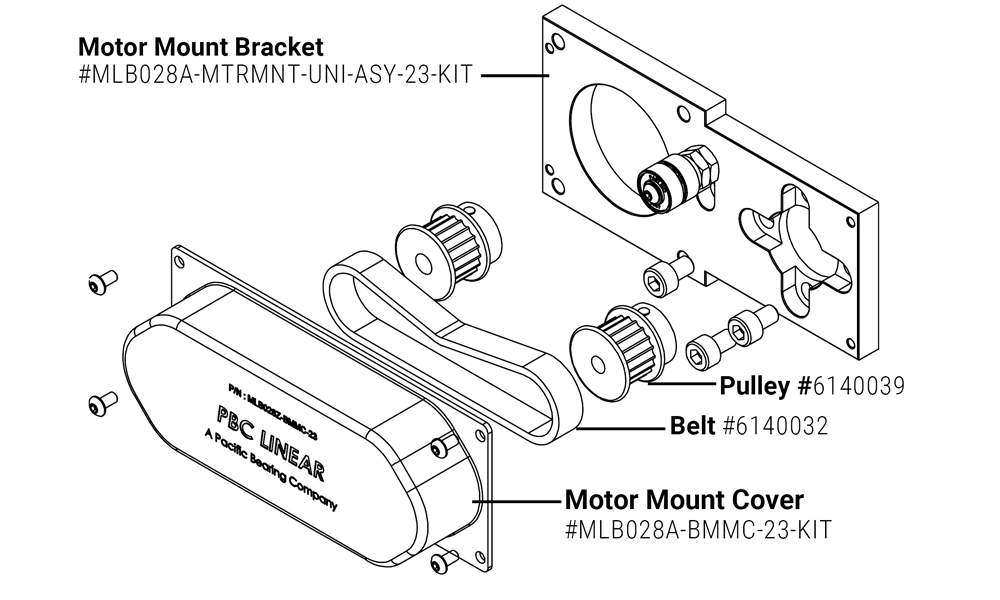
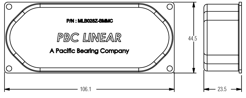
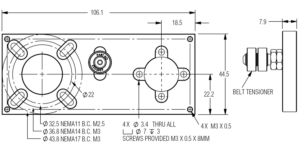
Motor Mount Assembly - NEMA 23
Includes:
| (1) Motor Mount Cover (4) BHCS M3 x 0.5 x 8 mm |
P/N: MLB028A-BMMC-23-KIT |
Includes:
| (1) Motor Mount Bracket (3) SHCS M5 x 0.8 x 8 mm |
P/N: MLB028A-MTRMNT-UNI-ASY-23-KIT |
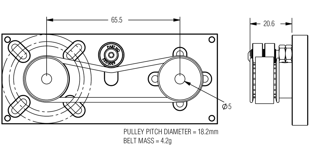
Includes:
| (1) Pulley Belt (3 mm pitch) | P/N: 6140032 |
| (1) Timing Pulley, 9mm x 6.35 mm | P/N: 6140039 |
| (1) Timing Pulley, 9 mm x 5 mm | P/N: 6140035 |
Mounting Hardware
Clamps, Plates &
Sensor Kits
Dovetail Clamps
Two screw design helps ensure quick and easy alignment during
installation.
Kit Includes:
(2) M3 Dovetail Clamp
(4)
M3 x 10mm SHCS


| Single Dovetail Clamp Only | P/N: MLA028A-HDC-M3 |
| Dovetail Clamp Kit | P/N: MLA028A-HDC-M3-KIT |
Riser Plates
Includes:
- (4) M3 x 10mm SHCS
- (2) M3 Dovetail Clamp
- (2) M5 x 16mm SHCS
- (1) 8mm or 15mm Riser Plate
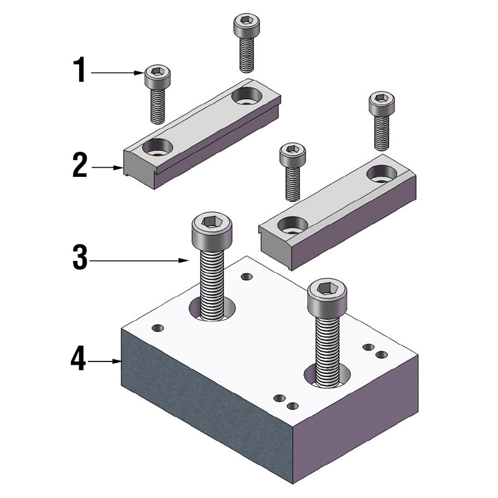
Recommended for NEMA 14 & 17 Motor
| 8 mm Riser Plate only | P/N: MLA028A-RSRPLT-08 |
| 8 mm Riser Plate Kit | P/N: MLA028A-RSRPLT-08-KIT |
Recommended for NEMA 23 Motor
| 15 mm Riser Plate only | P/N: MLA028A-RSRPLT-15 |
| 15 mm Riser Plate Kit | P/N: MLA028A-RSRPLT-15-KIT |
Riser Plate Sensor Kit
Kit Includes:
(1) Riser plate (8 or 15mm)
(2) Dovetail
clamps
(4) M3 x 10mm screws
(1) M3 x 12mm screw
(1) M3 x 6mm screw
(2)
M5 x 16mm screw (optional)
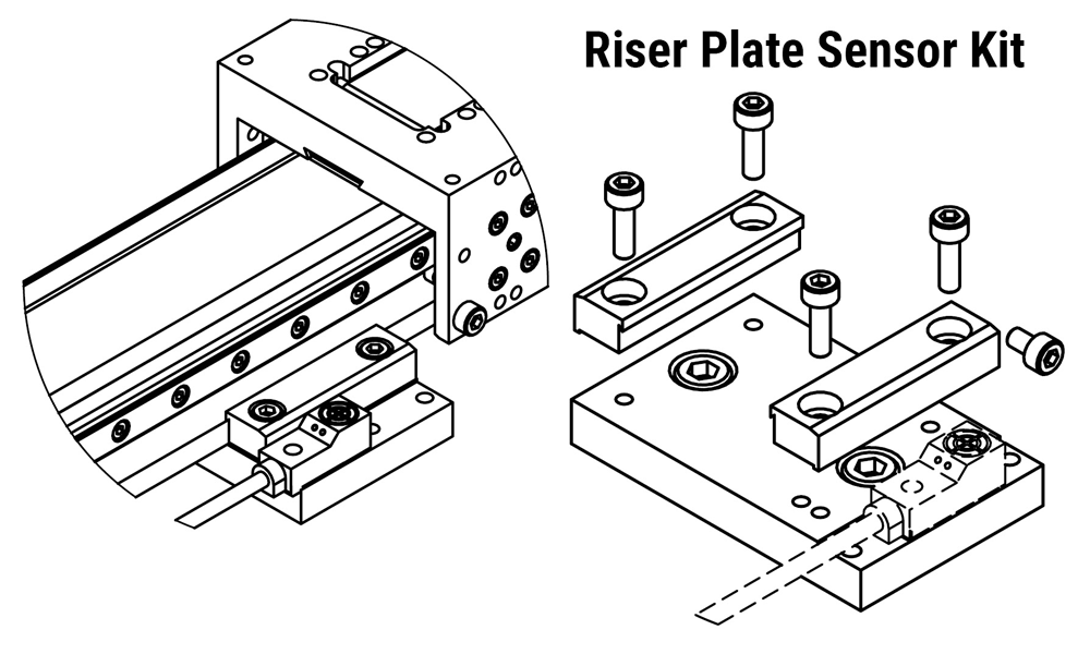
Compatible Sensors: OM-E2S-W2 style
Typical
Applications: ML Actuator gantry’s with (2) linear guides
| Riser Plate Sensor Kit | P/N: MLA028A-RSRPLT-08A-KIT |
| Riser Plate Sensor Kit | P/N: MLA028A-RSRPLT-15A-KIT |
Linear Guide Sensor Kit
Kit Includes:
(1) Bracket
(3) M3 X 4mm screws
(1) Flag, 5mm
sensing distance
(1) OM-Y92E-C1R6 Bracket
(1) M4 X 5mm set screw
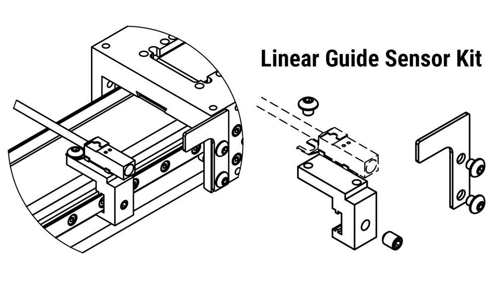
Compatible Sensors: OM-E2S-Q1 style
Typical
Applications: ML Actuators with one or two linear guide(s)
| Linear Guide Sensor Kit | P/N: MLB028A-BRKTA-KIT |
T-Slot Sensor Kit
Kit Includes:
(1) Bracket
(1) M2 X 8mm screw
(1) M2 nut
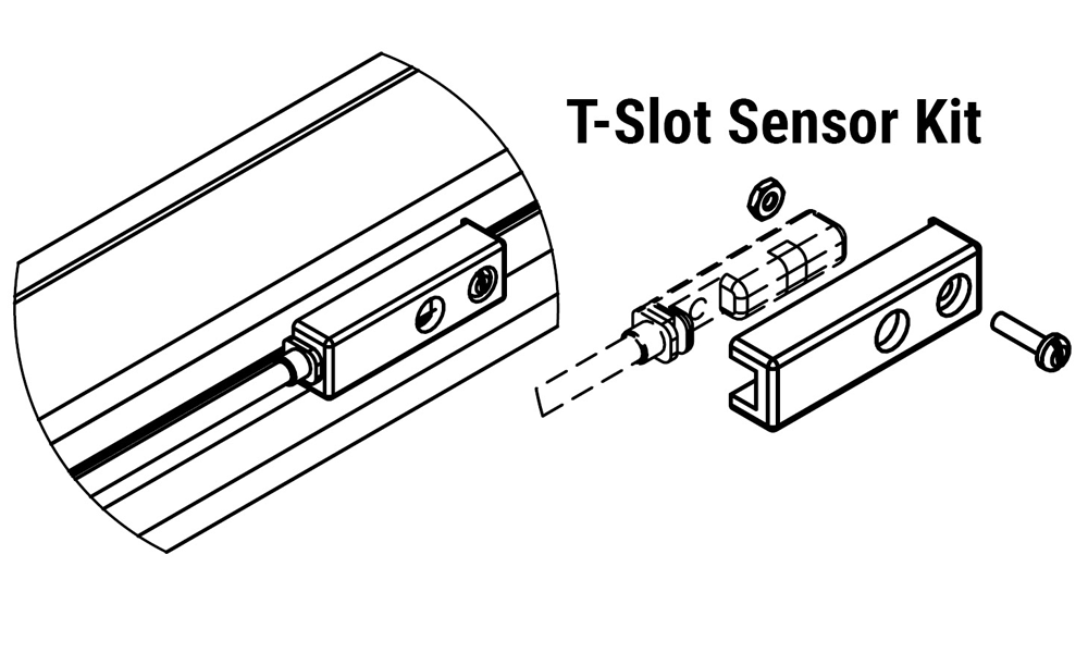
Compatible Sensors: PBC Linear 6200XXX Series
Sensors
Typical Applications: ML Actuator with zero or one
linear guide(s)
| T-Slot Sensor Kit | P/N: MLA028A-SENADT-KIT |
*Note: Sensor mounting kits do not include a sensor. The appropriate sensor should be ordered separately.
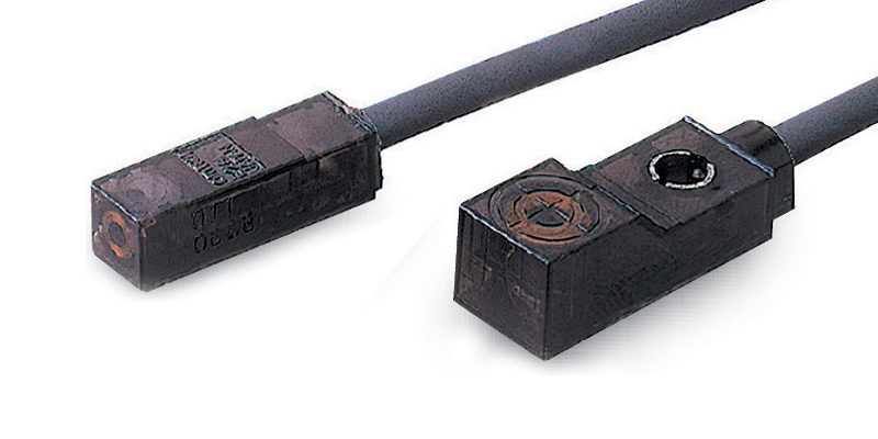
Proximity Sensors
Super Compact Proximity Sensors
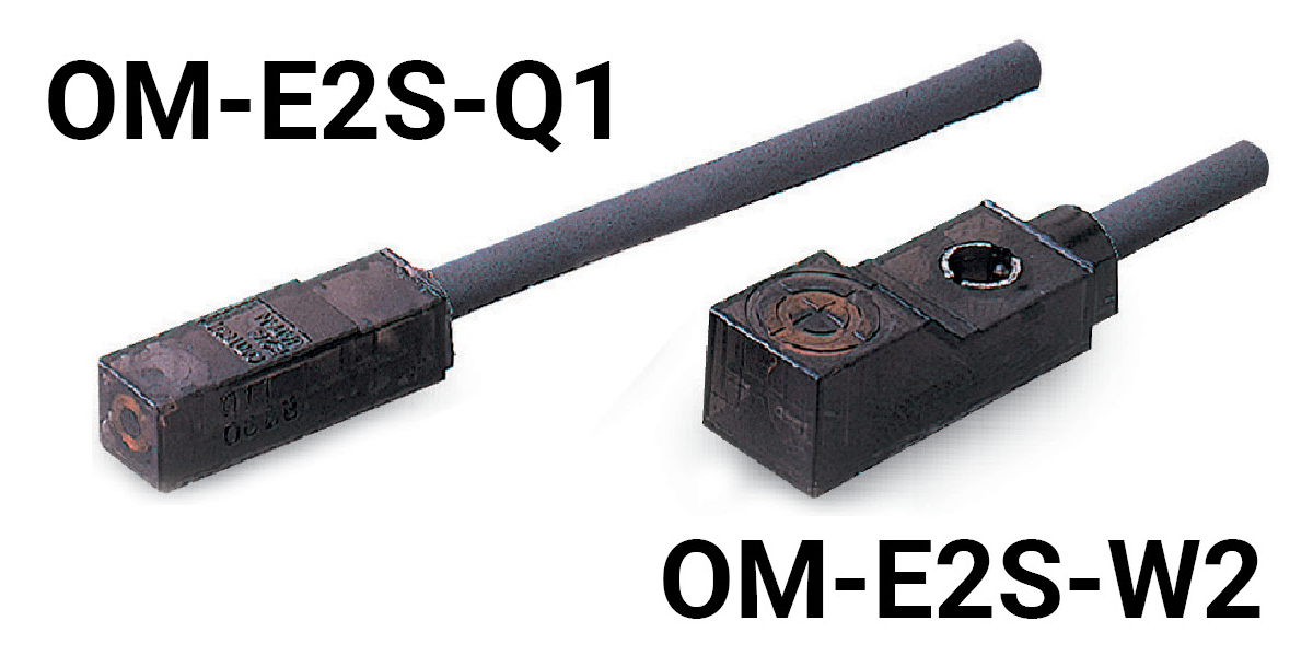
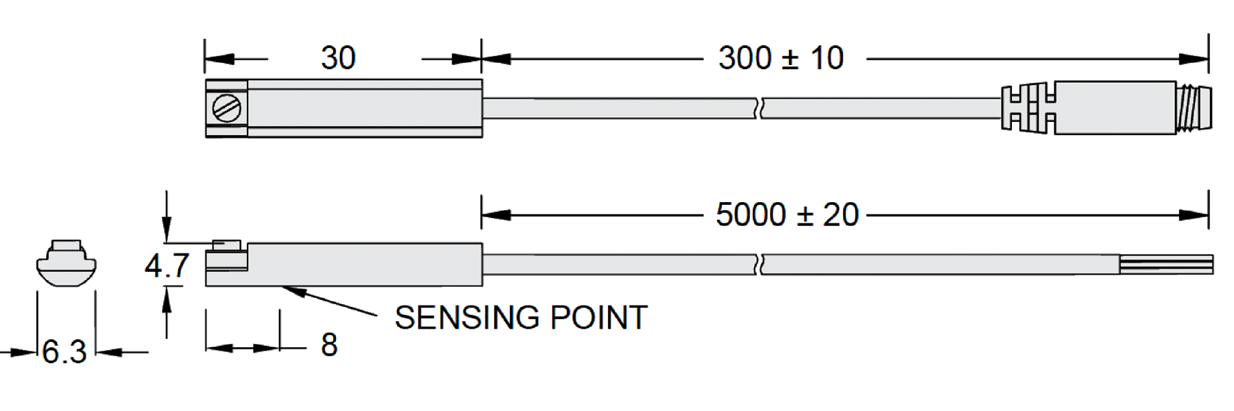
Note: 2.9-dia. vinyl-insulated round cable with 2/3 conductors. (Conductor cross section: 0.14 mm2, Insulator diameter: 0.9 mm), Standard length: 1m
| Sensing Surface |
Sensing Distance |
Sensor Series |
Output Configuration |
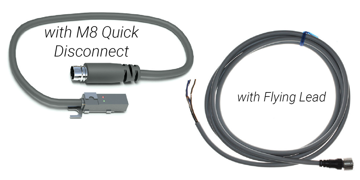
Cable: 5 m Flying Lead | Cable: 275 mm M8 Quick Disconnect | ||
|---|---|---|---|---|---|---|---|
| Normally Open (NO) | Normally Closed (NC) | Normally Open (NO) | Normally Closed (NC) | ||||
| End | 1.6 mm | OM-E2S-Q | NPN | OM-E2S-Q13-□ | OM-E2S-Q14-5M | OM-E2S-Q13-U2 | OM-E2S-Q14-U2 |
| PNP | OM-E2S-Q15-□ | OM-E2S-Q16-5M | OM-E2S-Q15-U2 | OM-E2S-Q16-U2 | |||
| Front/Top | 2.5 mm | OM-E2S-W | NPN | OM-E2S-W23-□ | OM-E2S-W24-5M | OM-E2S-W23-U2 | OM-E2S-W24-U2 |
| PNP | OM-E2S-W25-□ | OM-E2S-W26-5M | OM-E2S-W25-U2 | OM-E2S-W26-U2 | |||
| Bottom | n/a | PBC Linear 6200XXX |
NPN | ||||
| PNP | |||||||
□ = length of cable; 5M” = 5 meters with flying lead; U2 = 275mm with quick disconnect
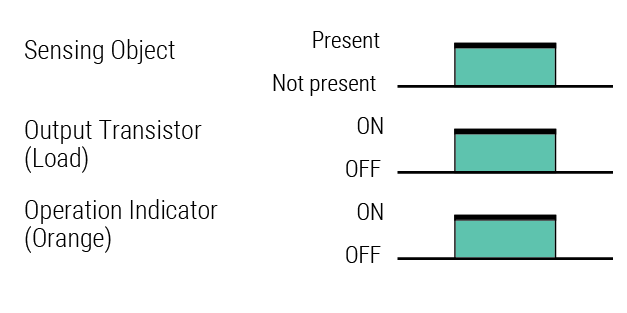
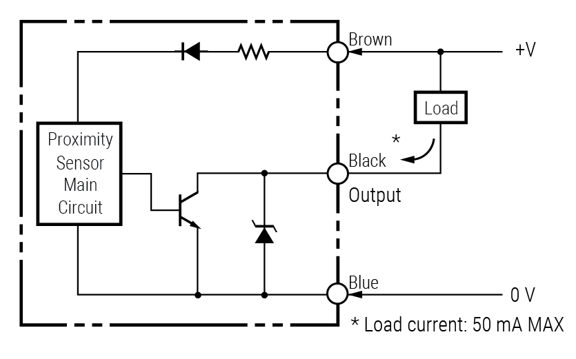
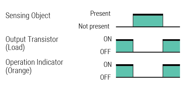
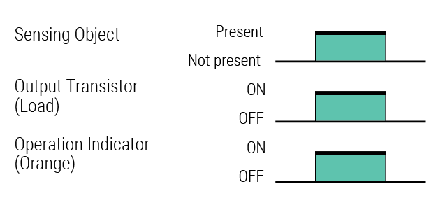
| Operation Status | Output Configuration | P/N # | Timing Chart | Output Circuits |
|---|---|---|---|---|
| NO | NPN | OM-E2S-W23-□ OM-E2S-Q13-□ |
 |
 |
| NC | NPN | OM-E2S-W24-□ OM-E2S-Q14-□ |
 |
|
| NO | PNP | OM-E2S-W25-□ OM-E2S-Q15-□ |
 |
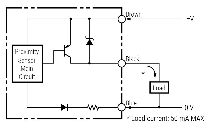 |
| NC | PNP | OM-E2S-W26-□ OM-E2S-Q16-□ |
 |
Magnetic Sensor Switch Specifications
Dimensional
Schematics

NPN (Current Sinking)
PNP (Current Sourcing)
Pinout
| Type | 6200096 | 6200154 | 6200153 | 6200155 | 6200269 | 6200270 | 6200271 | 6200272 |
|---|---|---|---|---|---|---|---|---|
| End Connector | Quick Disconnect | Wire | ||||||
| Wire Length | 300 mm | 5 m | ||||||
| Sensor Type | NPN | PNP | NPN | PNP | ||||
| Switching Logic (Solid State Output) |
NC | NO | NC | NO | NC | NO | NC | NO |
| Operative Voltage | 10–30V DC | |||||||
| Switching Current | 200 mA MAX | |||||||
| Contact Rating | 6 W MAX | |||||||
| Current Consumption | 20 ma @ 24V DC MAX | |||||||
| Voltage Drop | 1.5V MAX | |||||||
| Leakage Current | 0.05 mA MAX | |||||||
| Cable | Ø3 mm, 3 wire, polyurethane | |||||||
| Indicator | Red | Yellow | Yellow | Yellow | Red | Yellow | Yellow | Yellow |
| Operating Frequency | 1000 Hz | |||||||
| Magnet Requirement (Note 1) | 50 | 65 | 50 | 65 | 50 | 65 | 50 | 65 |
| Temperature Range | -10–70˚C (+14–158˚F) | |||||||
| Shock (Note 2) | 50 g | |||||||
| Vibration (Note 3) | 9 g | |||||||
| Enclosure Classification | IEC 529 IP 67 (NEMA 6) | |||||||
| Protection Circuit | Reverse polarity, Short-circuit | |||||||
Notes:
- Units: Gauss Parallel. Measuring standard target: Ø15.5 x Ø8 x 5t (Anisotrophy rubber magnet)
- Sine wave • X Y Z three directions • three times each direction • 11 ms each time
- Double amplitude 1.5 mm • 10Hz–55Hz–10Hz (Sweep 1 min.) • X Y Z three directions • 1 hour each time
| Model P/N: | OM-E2S-W13 OM-E2S-W14 |
OM-E2S-W23 OM-E2S-W24 |
OM-E2S-W15 OM-E2S-W16 |
OM-E2S-W25 OM-E2S-W26 |
|
|---|---|---|---|---|---|
| Sensing surface | Front | Top | Front | Top | |
| Sensing distance | 1.6 mm ± 15% | 2.5 mm ± 15% | 1.6 mm ± 15% | 2.5 mm ± 15% | |
| Set distance | 0 to 1.2 mm | 0 to 1.9 mm | 0 to 1.2 mm | 0 to 1.9 mm | |
| Differential travel | 10% MAX of sensing distance | ||||
| Detectable object type | Ferrous metal | ||||
| Standard target object | Iron, 12 x 12 x 1 mm | Iron, 15 x 15 x 1 mm | Iron, 12 x 12 x 1 mm | Iron, 15 x 15 x 1 mm | |
| Response frequency (see note) |
1 kHz min. | ||||
| Power supply voltage (operating voltage range) |
12 to 24V DC, ripple (p-p): 10% max. (10 to 30V DC) | ||||
| Current Consumption | 13 mA max. at 24 VDC (no-load) | ||||
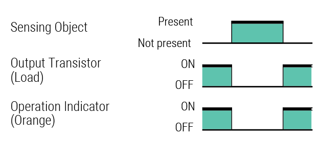
| Operation Mode (with sensing object approaching) |
OM-E2S-_ _ 3 models: NO OM-E2S-_ _ 4 models NC |
||||
| Control Output | Load Current | NPN open collector output 50 mA max. (30 V DC max.) |
PNP open collector output 50 mA max. (30 V DC max.) |
||
| Residual voltage | 1.0 V max. with a load current of 50 mA and a cable length of 1 m |
||||
| Indicator | Operation indicator (orange) | ||||
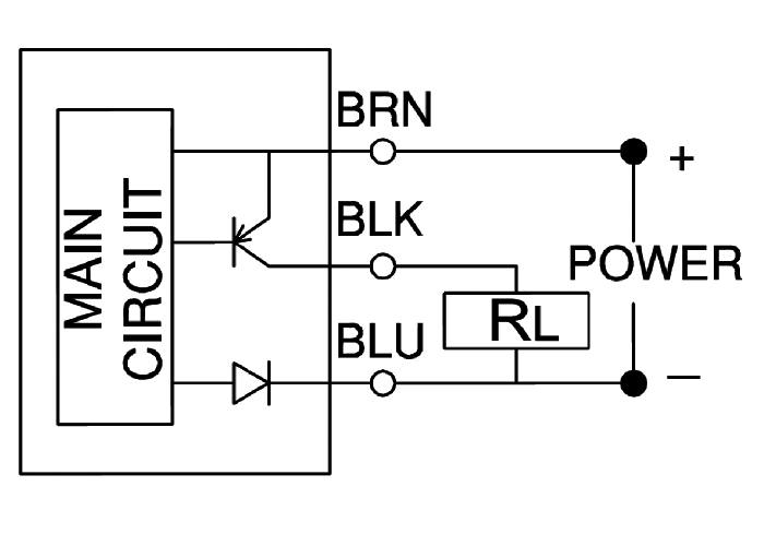
| Protection Circuits | Reverse polarity connection and surge absorber | ||||
| Ambient temperature | Operating | -25˚C to 70˚C (-13˚F to 158˚F) with no icing or condensation |
|||
| Storage | -40˚C to 85˚C (-40˚F to 185˚F) with no icing or condensation |
||||
| Ambient humidity | Operating | 35% to 90% (with no condensation) | |||
| Storage | 35% to 95% (with no condensation) | ||||
| Temperature influence | ± 15% max. of sensing distance at 23˚C in the temperature range of -25 to 70˚C |
||||
| Voltage Influence | ± 2.5% MAX of sensing distance in rated voltage range ± 10% |
||||
| Insulation resistance | 50 M MIN (500V VDC) between current carry parts and case |
||||
| Dielectric strength | 1,000 VAC, 50/60 Hz for 1 min between current carry parts and case |
||||
| Vibration resistance | Destruction: 10 to 55 Hz, 1.0 mm double amplitude for 2 hours each in X, Y and Z directions |
||||
| Shock resistance | Destruction: 500 m/s² (1640 ft/s²) 3 times each in X, Y and Z directions |
||||
| Connection Method | Pre-wired standard length 1 m (39.37 in) | ||||
| Weight (packed state) | Approx. 10 g (0.35 oz) | ||||
| Material/Case | Polyarylate resin | ||||
Maintenance Kit System Parts • Seal Strip Kit
Seal strips are engineered to last the life of the system. In the event that the strip becomes damaged by environmental contamination, PBC Linear offers a replacement seal strip kit.
Kit Includes:
(Carriage bracket sold separately.)
- (1) Seal Strip - Ultra-wear resistant MDS nylon
- (1) Retainer Bracket
- (1) Adjuster Bracket
- (3) PHC M2 x 0.4 x 5 mm
- (1) Hexagon Nut, M2 x 0.4
- (4) Bearings
| Seal Strip Kit | P/N: MLA028A-SSAR-KIT |
Seal strip is 725 mm in length and can be cut shorter using sharp pair of scissors.