Gliding Surface Technology
Product Comparison
Applications
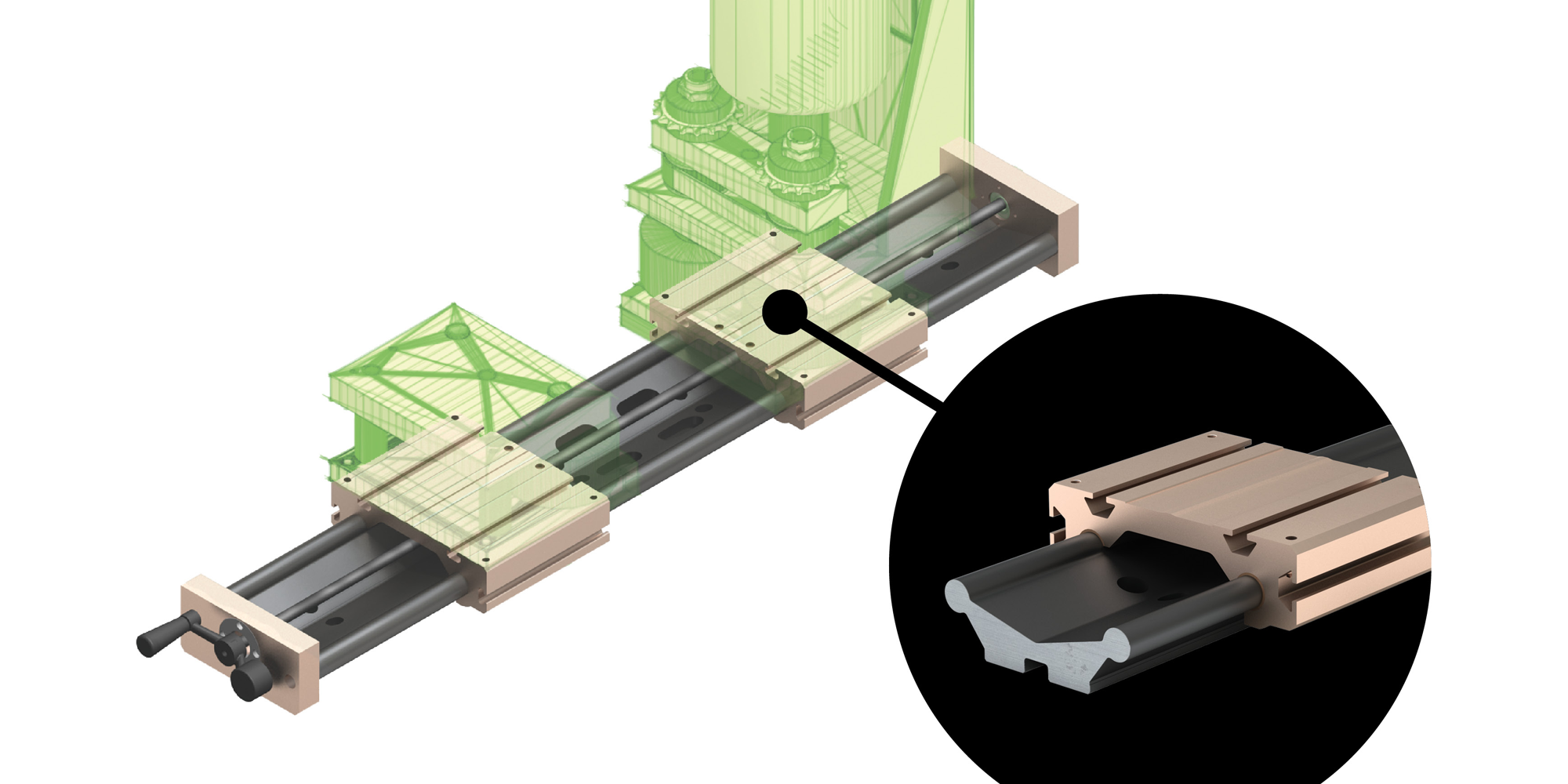
Heavy Duty Vise
With static load capacities up to 1000 lbs (453 kg) and the multiple-carriage option, Uni-Guide™ is an ideal drop-in solution for heavy duty applications.
Medical and Laboratory Equipment
The self-lubricating Frelon® bearing materials are ideal for environments where no grease or lubrication can be present.
Uni-Guide provides smooth and quiet linear motion in a simple, compact assembly that
is ideal for the medical and laboratory industry.
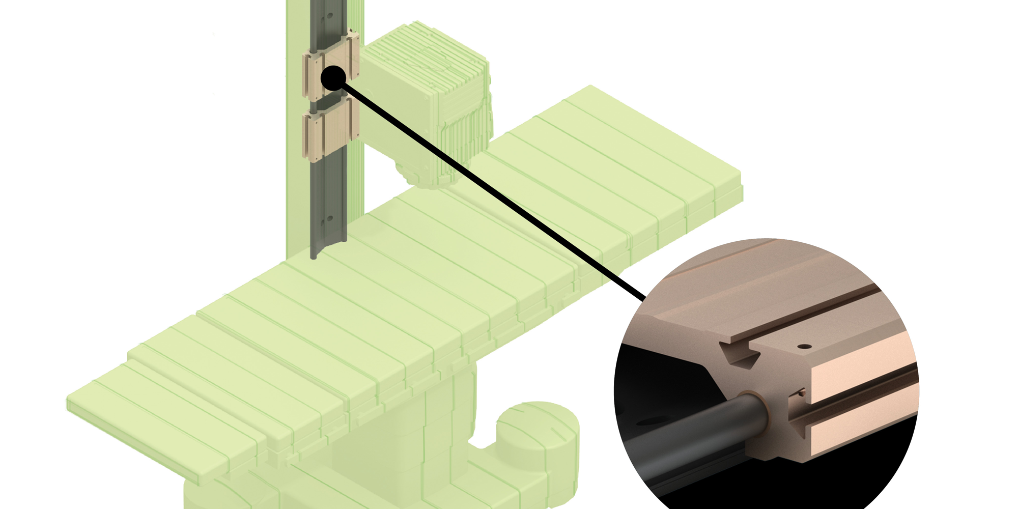
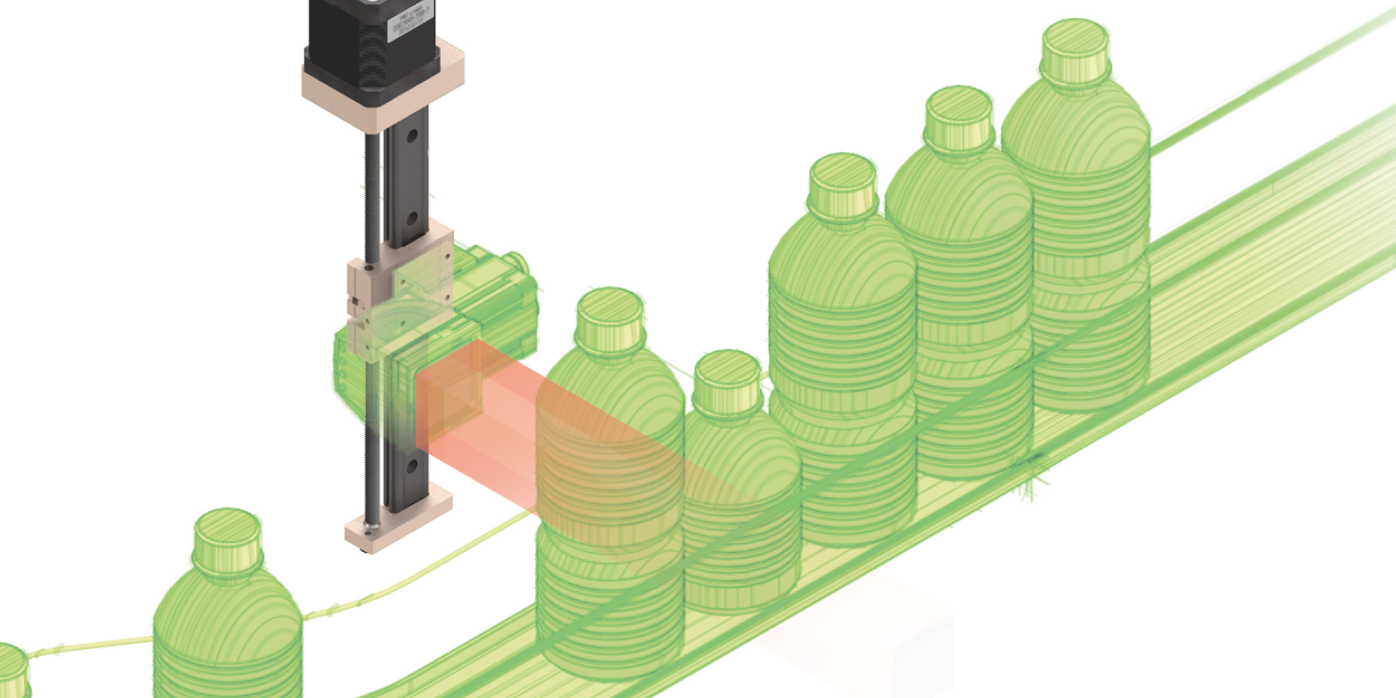
Automation and Assembly Line Gripper
The two-piece, aluminum designed Uni-Guide, is a unique assembly that eliminates
tolerance stack up and can be easily integrated into existing applications.
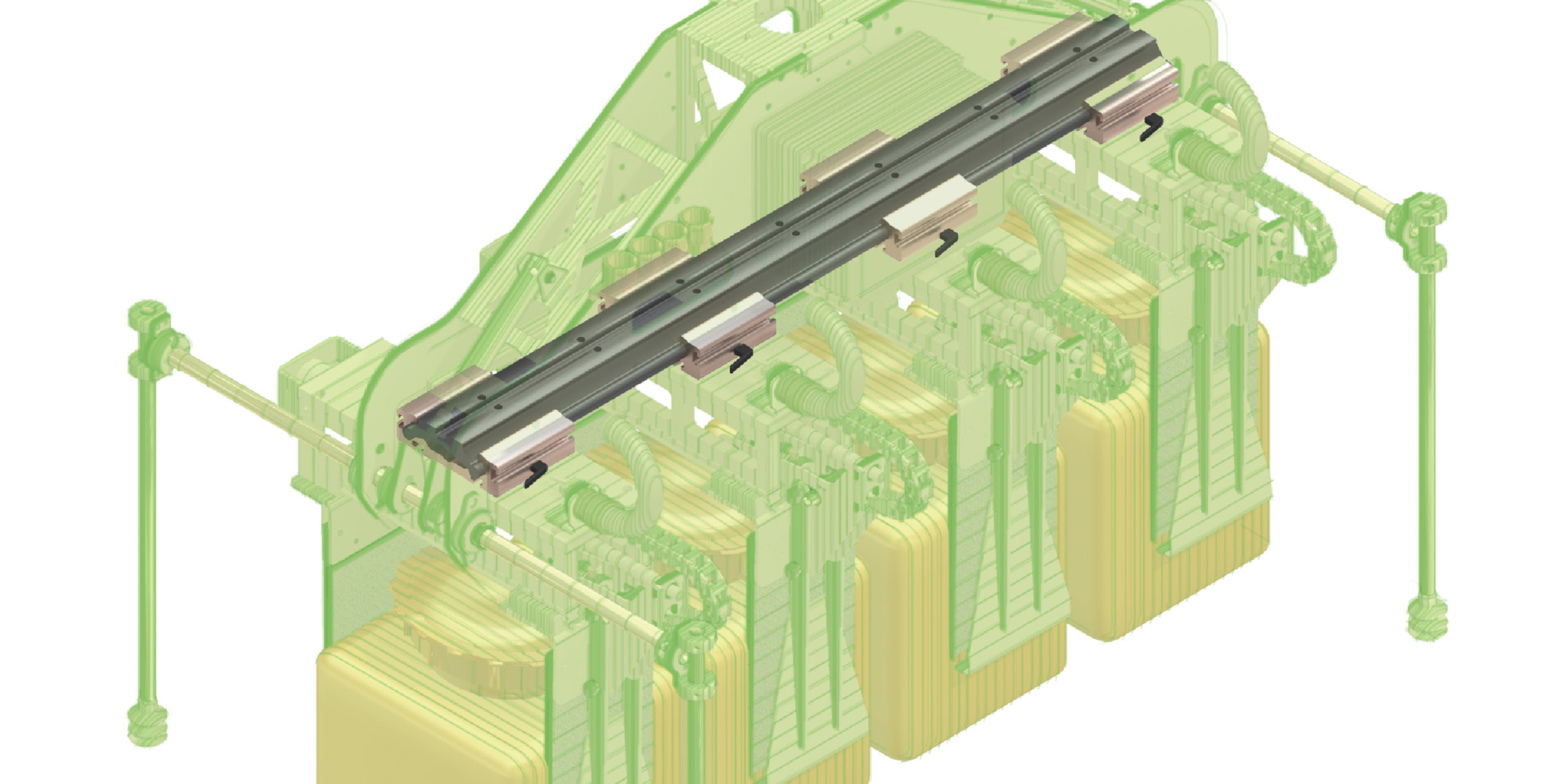
Vision, Sensors, and Scanning
GST rail and carriages provide consistent smooth performance in vision applications
due to not having any metal-to-metal contact.
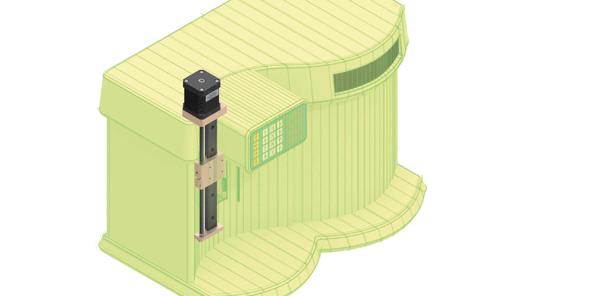
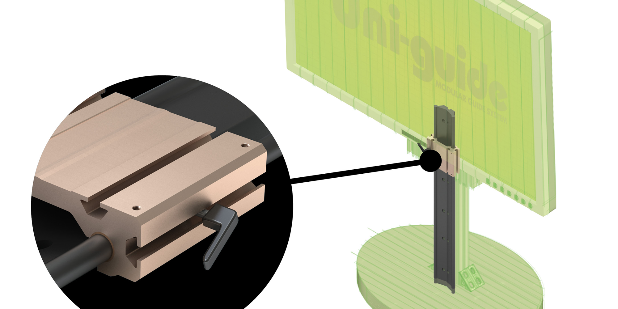
Audio/Visual Display Mounts
Uni-Guide™ provides a versatile solution for display mounts. Features such as hand
cranks, hand brakes and motors are available.
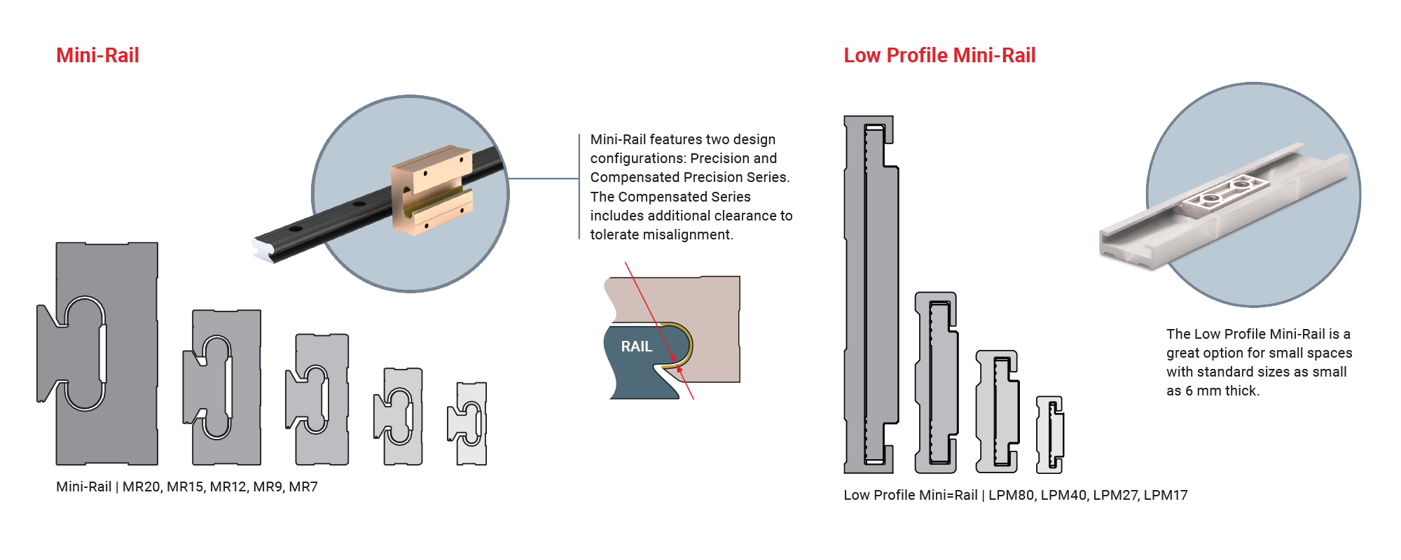
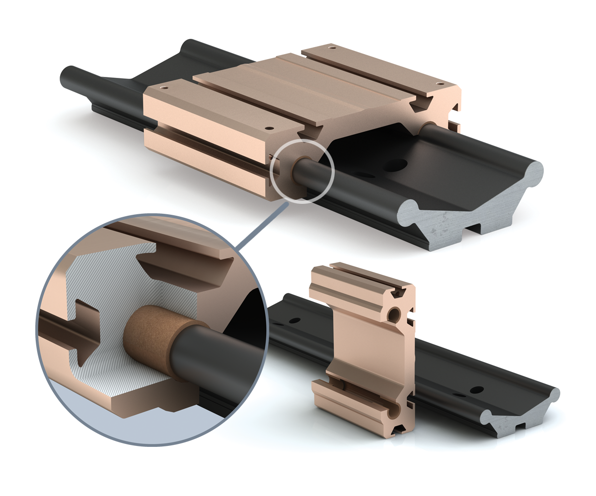
Mini-Rail
Product Overview
An economical alternative to conventional miniature linear guides, Mini-Rail requires little maintenance, is dimensionally interchangeable with industry standard sizes and is maintained in stock for quick delivery. Mini-Rail miniature linear guides are available in lengths up to 3600mm, meaning no cumbersome butt joints. These guides are precision manufactured out of lightweight aluminum alloys to ensure long life and corrosion resistance.
- Ceramic coated aluminum rail and anodized aluminum carriage
- Self-lubricating FrelonGOLD® Liner
- Compact design leaves a small footprint
- Corrosion resistance makes Mini-Rail ideal in harsh environment
- No rolling elements eliminates possibility of catastrophic failure
- Withstands vibration and shock
- Available in five sizes: 7, 9, 12, 15, and 20 mm
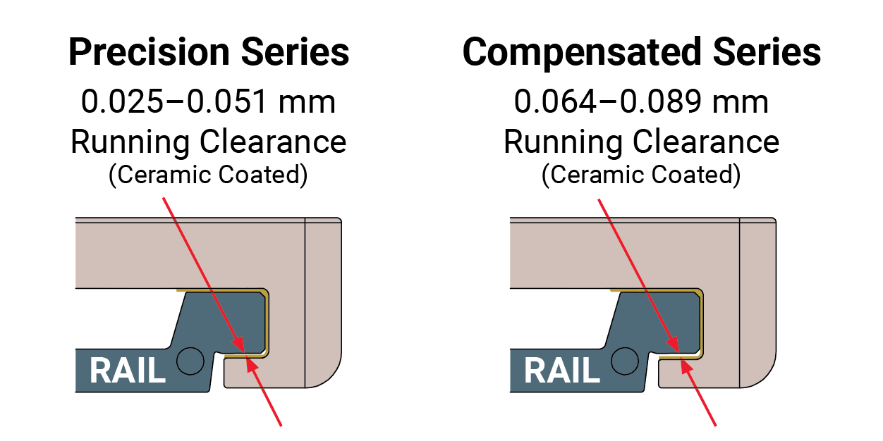
Carriage Configurations
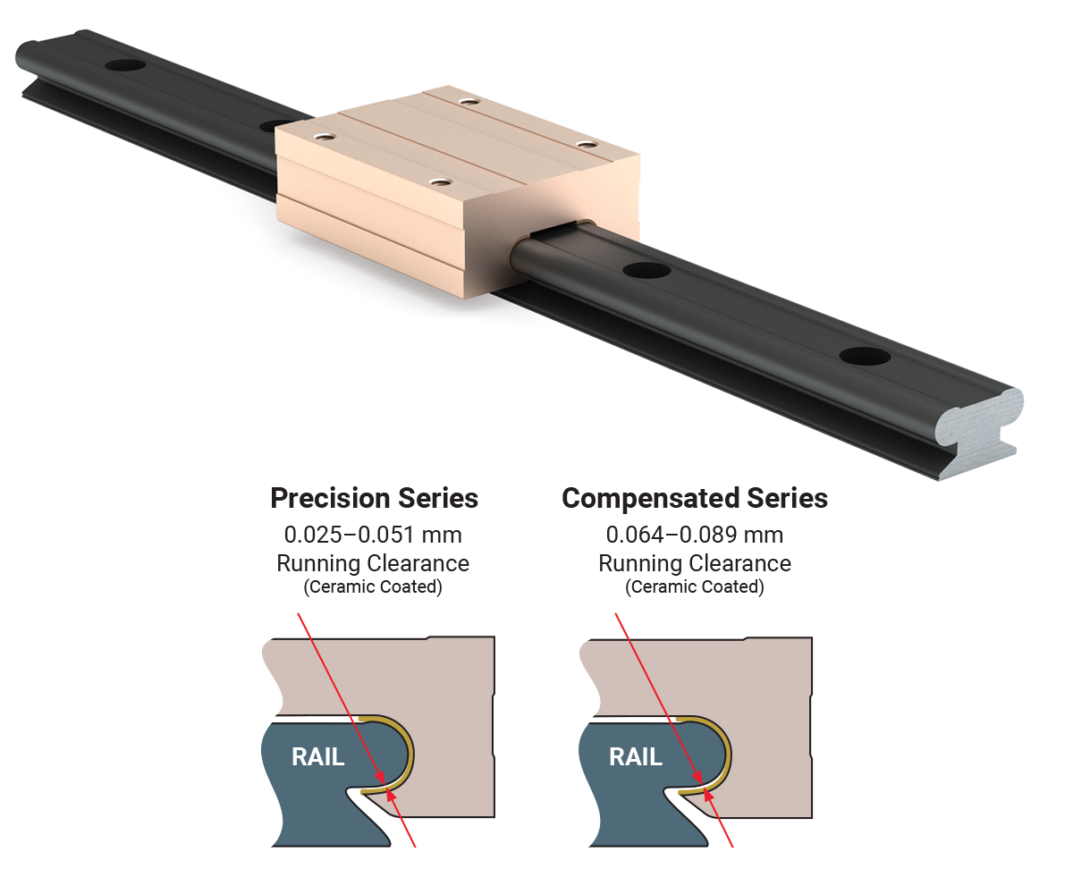
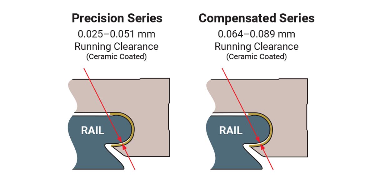
Precision Series: Ceramic coated rails and anodized carriages are
corrosion resistant. FrelonGOLD self-lubricating liner delivers the best overall
performance, the highest loads, the best wear life, and speeds. Most precise running
clearance for high precision applications.
Compensated
Series: Same as Precision Series except with additional clearance
provided to tolerate misalignment.
Applications
• Medical Precision
• Mobile Home Components
• Packaging
• Food
Processing
• Product Movement
• Automation
• Semi-conductor
•
Printing
• Electronics
Accessories
• Hand Brake
Ordering Information
Carriage
| Mini-Rail | Series | Nominal Sizes | Carriage | Carriage Option |
| MR | XX | C | BL | |
Mini-RailMiniature Linear Guide SeriesNo Entry - Precision Series C - Compensated Precision Series Nominal Sizes07 mm 09 mm 12 mm 15 mm 20 mm CarriageC - Carriage Carriage OptionNo Entry - None BL -
Hand Brake |
Note: Mini-Rail carriages are matched to the rails at the time of the order. Adding carriages at a later date may result in an unsatisfactory fit between carriage and rail.
Rail
| Mini-Rail | Nominal Sizes | Rail | Rail Length | |
| MR | XX | R | - | 0100 |
Mini-RailMiniature Linear Guide Nominal Sizes07 mm 09 mm 12 mm 15 mm 20 mm RailR - Rail Rail Length3600 mm MAX |
Carriage And Rail Assembly
| Mini-Rail | Series | Nominal Sizes | Rail Length | Carriage Option | Number of Carriages | |||
| MR | XX | - | 0100 | - | BL | - | X | |
Mini-RailMiniature Linear Guide SeriesNo Entry - Precision Series C - Compensated Precision Series Nominal Sizes07 mm 09 mm 12 mm 15 mm 20 mm Rail Length3600 mm MAX Carriage OptionNo Entry - None BL -
Hand Brake Number of Carriages1 - One Carriage 2 - Two Carriages 3 - Three Carriages 4 -
Four Carriages |
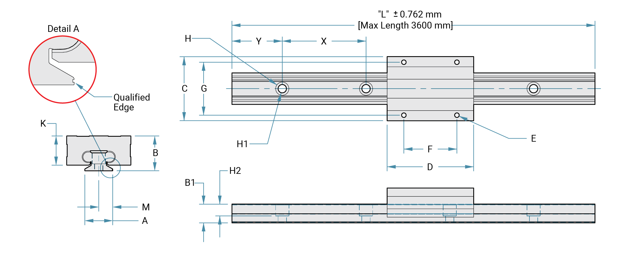
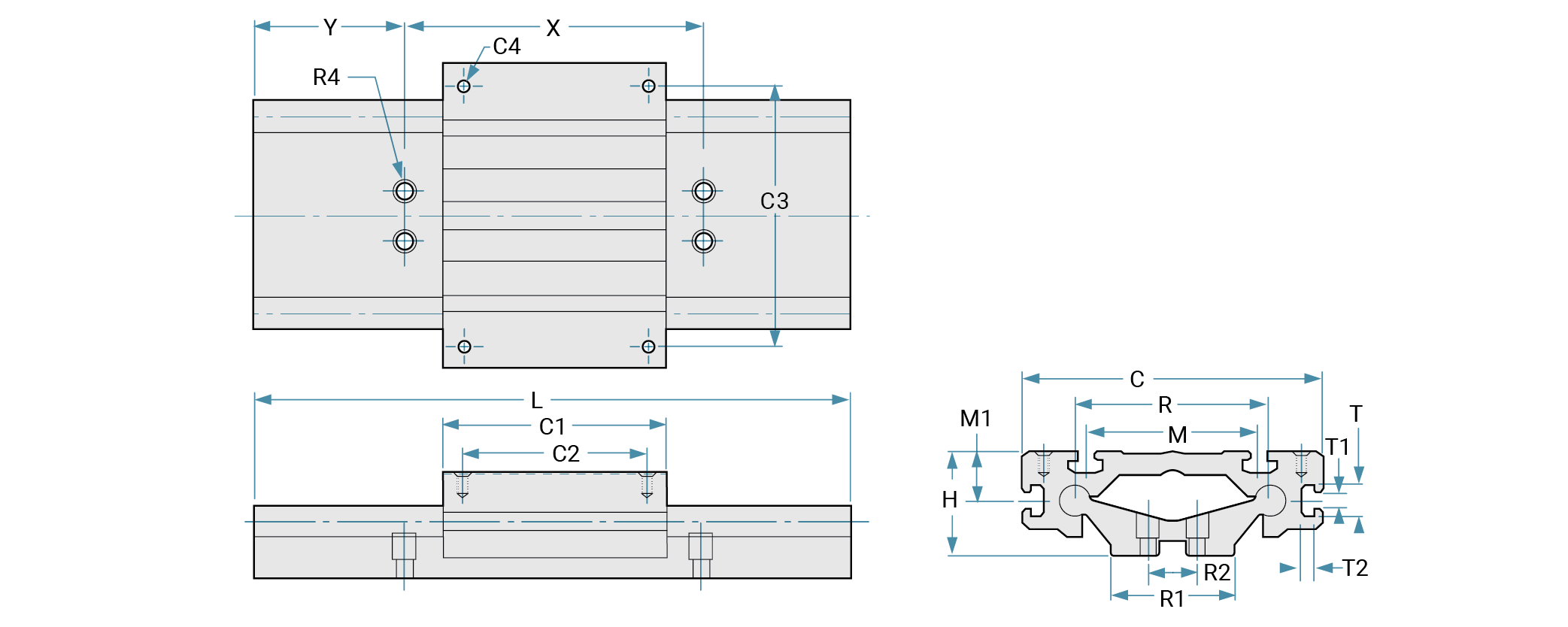
Dimensions
Maximum Length: 3600 mm
Materials: 6061-T6 aluminum rail and carriage, FrelonGOLD®
Max V: 300 sfm for FrelonGOLD (1.524 m/s)
Max P: 3000 psi for FrelonGOLD (20.68 N/mm²)
| Part Number |
Running Clearance |
A | B | B1 | C | D | E | F | G | H | H1 | H2 | K | M | y | x | Rail Wt. Gram/mm |
Carriage Wt. Gram |
|
|---|---|---|---|---|---|---|---|---|---|---|---|---|---|---|---|---|---|---|---|
| Base Width mm |
Overall Height |
Rail Height |
Carriage Width |
Carriage Length |
Carriage Mtg. Hole Size |
Carriage Mtg. Hole Depth |
Carriage Mtg. Hole Ctr. to Ctr. |
Rail Hole Size |
Carriage Height |
Rail Mtg. Hole to Qualified Edge |
Rail Hole to End |
Rail Hole Ctr. to Ctr. |
|||||||
| MR7-xxx | 0.025-0.051 | 7 | 8 | 6.1 | 17 | 24 | M2 x 0.4 | THRU | 8 | 12 | 4.2 | 2.4 | 2.3 | 6.2 | 3.5 | 5.0 | 15 | 0.10 | 5.7 |
| MRC7-xxx | 0.064-0.089 | ||||||||||||||||||
| MR9-xxx | 0.025–0.051 | 9 | 10 | 7.1 | 20 | 30 | M3 x 0.5 | 13 | 15 | 4.5 | 2.6 | 3 | 8.0 | 4.5 | 7.5 | 20 | 0.16 | 8.5 | |
| MRC9-xxx | 0.064–0.089 | ||||||||||||||||||
| MR12-xxx | 0.025–0.051 | 12 | 13 | 8.0 | 27 | 34 | 15 | 20 | 6 | 3.5 | 3.5 | 10.7 | 6.0 | 10 | 25 | 0.22 | 20.0 | ||
| MRC12-xxx | 0.064–0.089 | ||||||||||||||||||
| MR15-xxx | 0.025–0.051 | 15 | 16 | 9.2 | 32 | 42 | 20 | 25 | 4.5 | 14.1 | 7.5 | 15 | 40 | 0.38 | 34.0 | ||||
| MRC15-xxx | 0.064–0.089 | ||||||||||||||||||
| MR20-xxx | 0.025–0.051 | 20 | 25 | 13.4 | 46 | 62 | M4 x 0.7 | 12.5 | 38 | 38 | 9.5 | 6 | 8.5 | 21.2 | 10 | 20 | 60 | 0.48 | 127.9 |
| MRC20-xxx | 0.064–0.089 | ||||||||||||||||||
Note: Cut-to-length rails are available up to 3600 mm. Standard
and cut-to-length rail ends are NOT coated. Fully coated rails are available upon
request for high volume quantity requirements. All carriage mounting holes are
through tapped except MR20 12.5mm of thread.
The “Y” dimension will remain
constant at one end unless requested otherwise. Add the overall length of the rail
to the part number (EX:“MR12-0220” for a Precision Series assembly with a 220mm
rail).
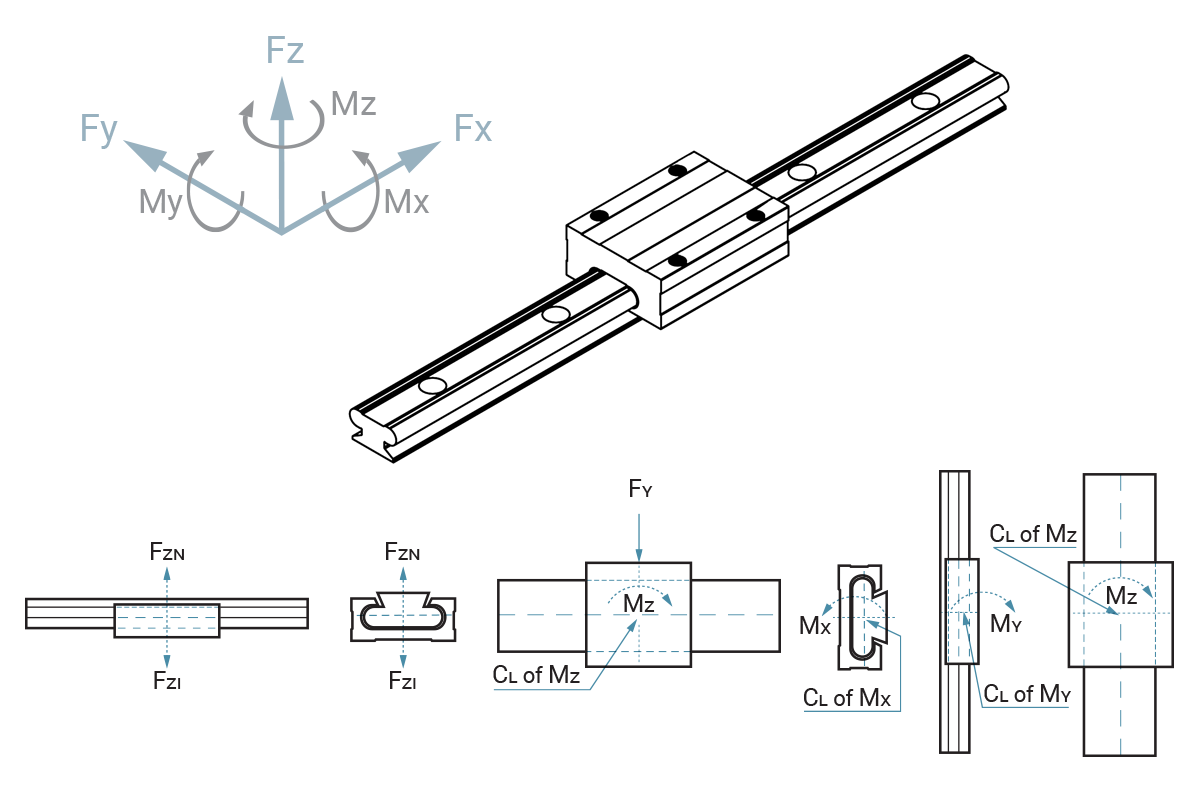
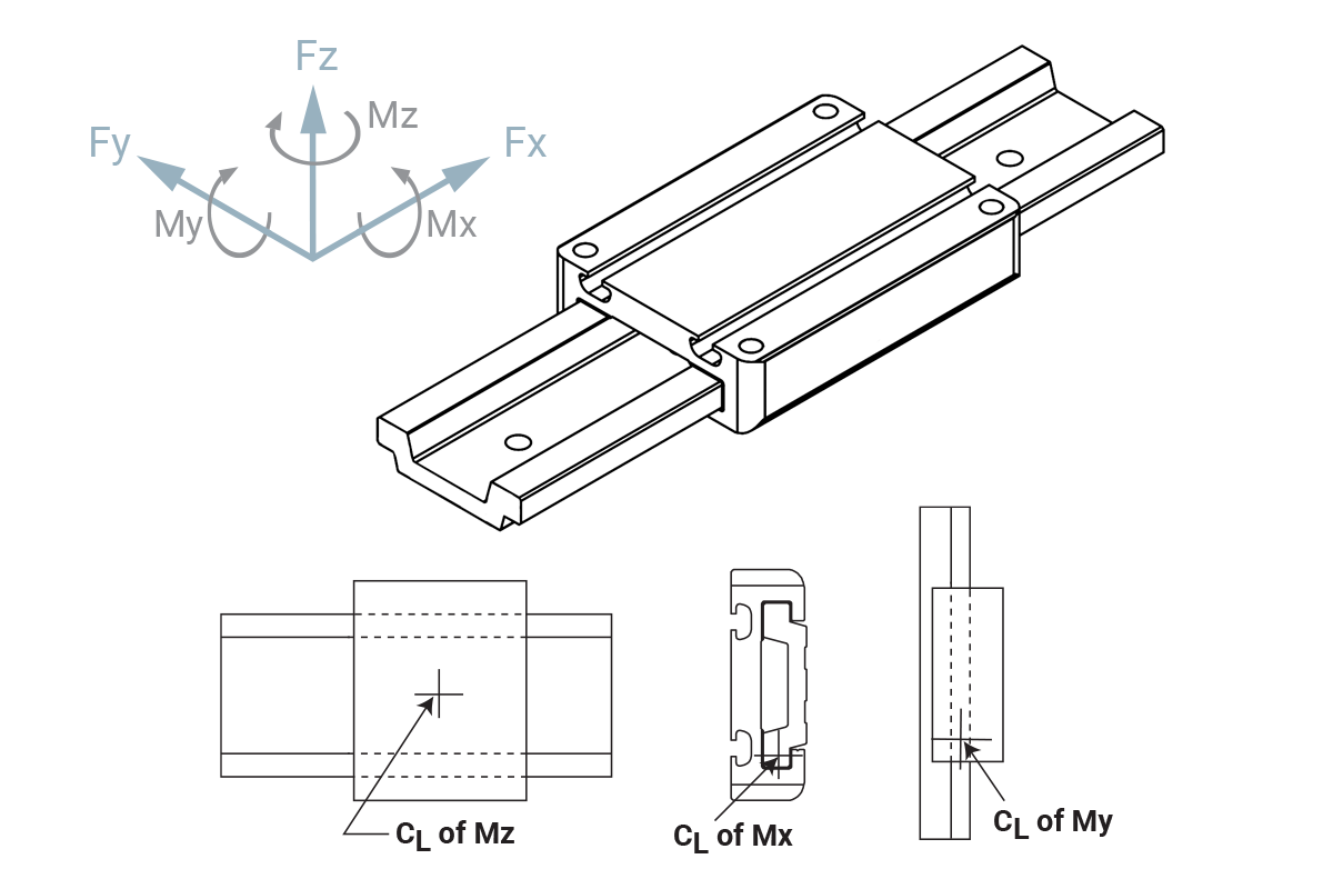
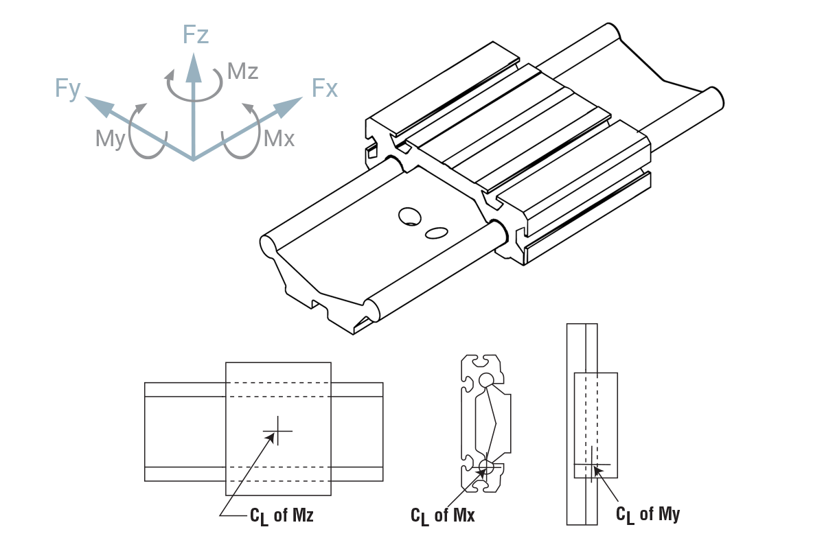
Static Load Data
The numbers below are for rails in a static condition. Refer to the calculations below to establish dynamic parameters.
| Fzn | Fzi | Fy | Mx | My | Mz | |
|---|---|---|---|---|---|---|
| Size | N | N | N | N-m | N-m | N-m |
| 7 | 445 | 89 | 133 | 1.8 | 1.8 | 2.3 |
| 9 | 667 | 125 | 222 | 3.2 | 3.2 | 5.0 |
| 12 | 1334 | 222 | 400 | 5.6 | 5.6 | 9.0 |
| 15 | 2224 | 356 | 667 | 9.0 | 9.0 | 15.1 |
| 20 | 3559 | 578 | 1112 | 14.7 | 14.7 | 24.9 |
Performance Ratings for Linear Motion
Plain bearings are rated by their limiting PV, which is a combination of load over a given surface area and the velocity.
| Bearing Material |
MAX. PV | MAX. P | MAX. V No Lubrication |
|---|---|---|---|
| Frelon GOLD® |
20,000 (psi x ft./min.) or 0.7 N/mm2 x m/s |
3000 psi or 20.68 N/mm2 |
300 sfm or 1.524 m/s |
PV = The performance measurement of plain
bearings.
PV = P x V, where P = pressure (load) in psi
(kgf/cm2)
V = velocity (speed) in sfm
(m/min.)
PV Example:
- Load = 85 psi
- Speed = 180 ft./min.
- PV = 85 x 180 = 15,300 PV
Note: All three parameters must be met by an application for the bearing to
perform properly.
Note: FrelonGOLD® bearing material
coefficient of friction is 0.125.
Cantilevered Loads
Binding of the carriage will occur if the 2:1 ratio for cantilevered loads and drive forces is exceeded. This principle is not load or force dependent. It is a product of the coefficient of frictions associated with plain bearings. Contact factory or website for additional information.

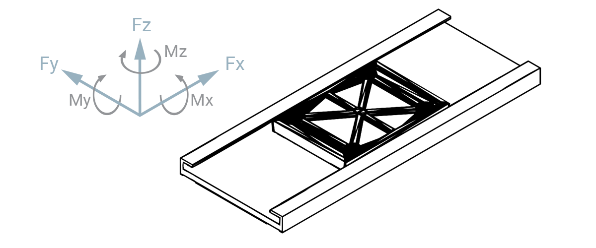
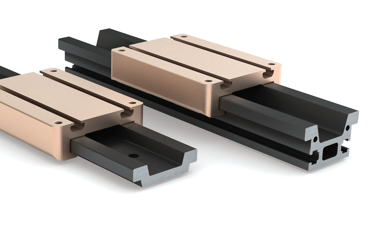
Low Profile Mini-Rail

Product Overview
Low Profile Mini-Rail is the perfect low cost solution for compact, low friction linear motion applications. The anodized aluminum rails offer a unit that is resistant to lubricants, fuels, dyes and weak acids. Being an industry standard interchangeable component, the LPM series is a fool-proof polymer slider.
Features and Benefits
- Low Cost
- Molded polymer slider with molded-in stainless steel threaded inserts
- Anodized aluminum rails
- Industry standard interchangeable
- Compact, low friction solution
- Resistant to contaminants, dyes, and weak acids
- Temperatures range: -35°C to +65°C
- Available in four sizes: 17, 27, 40, and 80 mm
- Running clearance is ≤ 0.5 mm
Applications
- Medical Equipment
- Packaging Precision
- Automation Industry
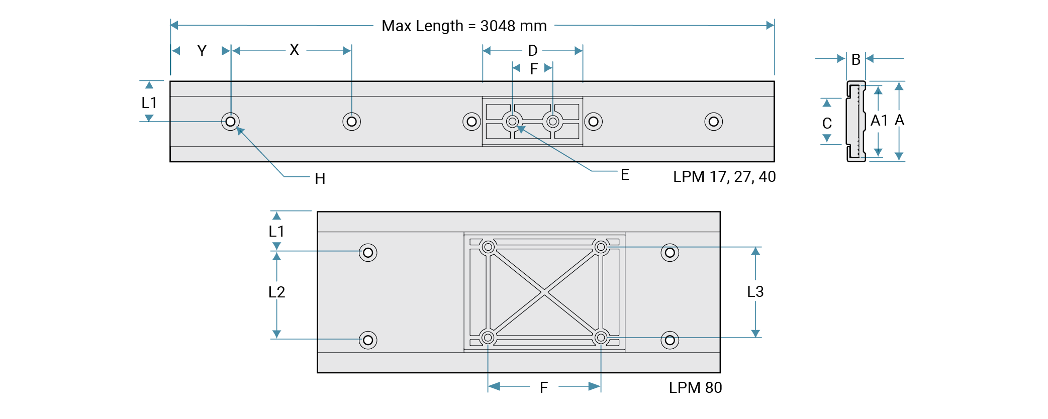
Dimensions
Materials: Polymer slider (UL 94 HB flammability rating) Molded-in
stainless steel thread inserts Anodized aluminum rails
Running
Clearance: Less than or equal to 0.5 mm
Maximum Velocity: 10 m/s
Load Reduction
Factor: 0.7-1.0 for low speed application; 0.4-0.7 for medium speed
application; 0.1-0.4 for high speed application
| Part Number |
A1 | A | B | C | D | E | F | H C’Bore |
L1 | L2 | L3 | Y | X | Carriage Wt. |
Rail Unit Wt. |
Load Capacity | |||||||||
|---|---|---|---|---|---|---|---|---|---|---|---|---|---|---|---|---|---|---|---|---|---|---|---|---|---|
| Fy | Fz | Mx | My | Mz | |||||||||||||||||||||
| mm | mm | mm | mm | mm | mm | mm | mm | mm | mm | mm | mm | g | g/mm | N | lb. | N | lb. | N-m | lb.-in | N-m | lb.-in | N-m | lb.-in | ||
| LPM17 | 14.6 | 17 | 6.0 | 9.6 | 25 | M3 x 0.5 | 14 | M3 SBHCS |
8.5 | N/A | N/A | 20 | 60 | 1.1 | 0.15 | 35 | 8 | 10 | 2.5 | 0.2 | 1.5 | 0.3 | 2.5 | 0.2 | 1.5 |
| LPM27 | 24 | 27 | 9.5 | 14 | 40 | M4 x 0.7 | 20 | M4 SBHCS |
13.5 | N/A | N/A | 20 | 60 | 4.8 | 0.33 | 130 | 30 | 85 | 20 | 1.0 | 10 | 2.5 | 20 | 1.0 | 10 |
| LPM40 | 36 | 40 | 9.5 | 23 | 50 | M4 x 0.7 | 20 | M4 SBHCS |
20 | N/A | N/A | 20 | 60 | 9.8 | 0.38 | 270 | 60 | 150 | 35 | 2.5 | 25 | 5.0 | 50 | 2.5 | 25 |
| LPM80 | 75.2 | 80 | 12.0 | 57 | 80 | M4 x 0.7 | 56 | M4 SBHCS |
20 | 40 | 45 | 25 | 150 | 32.3 | 1.07 | 515 | 120 | 250 | 55 | 7.0 | 60 | 14 | 125 | 7.0 | 60 |
Note: Apply a load reduction factor 0.25 on Fy rating if the system is used inverted.
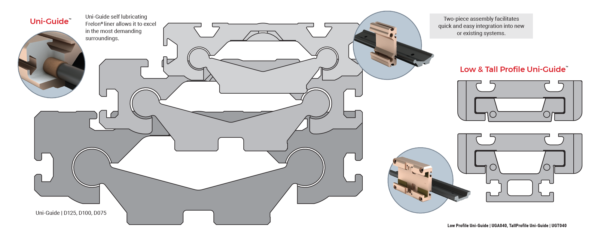
Low and Tall Profile Uni-Guide
Product Overview
The Low and Tall Profile Uni-Guides are solutions that maintain the proven advantages
of the standard Uni-Guide in a simple, low cost and compact assembly. This two-piece
assembly equipped with FrelonGOLD® liner creates a maintenance-free, smooth and
quiet linear motion solution.
The PBC Linear patented SIMO milling operation
creates a precision-machined rail and carriage surface providing tight tolerances
and alignment accuracy. The Low and Tall Profile Uni-Guides are available in both
the precision and compensated series, allowing varying amount of running clearance
to tolerate misalignment for a given application.
Features and Benefits
• Low cost
• Ceramic coated aluminum rail, standard anodized carriage with
FrelonGOLD liner
• Low wear, high load capacities, and maintenance free
operation
• Two-piece assembly facilitates a quick and easy integration into new
or existing systems
• No metal-to-metal contact, which eliminates catastrophic
failure
• Vibration damping and shock resistant
• Ideal for contaminated
environments and clean rooms - hard anodized aluminum prevents contaminants from
sticking
• Angled rail design ensures optimum washdown
• Operates well in a
wide temperature range
• Suitable for an extremely short stroke
Carriage Configurations
Precision Series: Ceramic coated rails and carriages are corrosion
resistant. FrelonGOLD self-lubricating liner delivers the best overall performance,
the highest loads, the best wear life, and speeds. Most precise running clearance
for high precision applications.
Compensated Series: Same as
Precision Series except with additional clearance provided to tolerate misalignment.
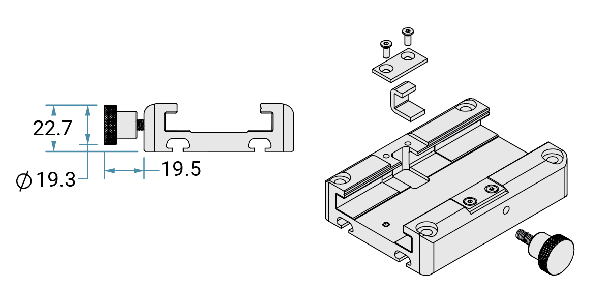
Accessories
• Hand Brake
• Felt Wick Lubrication - You will have to add lubrication to the
felt wick. If felt wick is installed in the carriage, remove carriage from rail and
add lubrication. If wick is shipped separate from carriage, add lubrication to felt
wick and install into carriage before operation.
Note: Does not apply to Standard Uni-Guide products.
Plain
bearings should comply with the 2:1 ratio rule.
Applications
• Medical equipment
• Laboratory equipment
Ordering Information
Rail
| Uni-Guide | Series | Internal/External Size | Identifier | Rail Length | Anodizing | Hole Pattern | Version | ||
| UG | A | 040 | R | - | XXXX | - | 0 | 0 | 0 |
Uni-GuideUG - Uni-Guide SeriesA - Low Profile T - Tall Profile Internal/External Size040 - 40 mm IdentifierR - Rail Rail LengthXXXX - Enter Length of Rail in Millimeters (2750 mm maximum) Anodizing0 - Standard Hole Pattern0 - Standard (60 mm) (UGA only) 1 - No holes (UGT only) Version0 - Standard |
Carriage
| Uni-Guide | Series | Internal/External Size | Identifier | Carriage Length | Running Clearance | Carriage Height | Frelon Type | Carriage Options | Version | |
| UG | A | 040 | C | - | X | X | 1 | G | X | 0 |
Uni-GuideUG - Uni-Guide SeriesA - Standard (used with both low profile and tall rail) Internal/External Size040 - 40 mm IdentifierC - Carriage Carriage Length0 - 100 mm 1 - 150 mm 2 - 200 mm Running ClearanceP - Precision (0.025 - 0.051 mm) C - Compensated (0.064 - 0.089) Carriage Height1 - Standard carriage w/t-slots Frelon TypeG - GOLD Carriage Options0 - None 1 - CHB (hand brake) 2 - JKM (lube option) 3 - Both Version0 - Standard |
Carriage and Rail Assembly
| Uni-Guide | Series | Internal/External Size | Rail Length | Carriage Length | Running Clearance | Frelon Type | Carriage Options | Number of Carriages | ||||
| UG | - | T | 040 | - | 0100 | - | 0 | P | G | 00 | - | 1 |
Uni-GuideUG - Uni-Guide SeriesA - Low Profile T - Tall Profile Internal/External Size040 - 40 mm Rail LengthXXXX - Enter Length of Rail in Millimeters 2750 mm MAX Carriage Length0 - 100 mm 1 - 150 mm 2 - 200 mm Running ClearanceP - Precision (0.025 - 0.051 mm) C - Compensated (0.064 - 0.089) Frelon TypeG - GOLD Carriage Options00 - None 10 - CHB (hand brake) 20 - JKM (lube option) 30 - Both 10 and 20 Carriage Options1, 2, 3, 4, 5 - Carriages |
Note:
- Specify Y dimension (hole to end) at time of order. Default end to first hole is 30 mm.
- 60 mm hole spacing provided for higher moment capacity. For low moment applications, every other hole may be used.
- FrelonGOLD® must be paired with standard anodized rail.
- "None” carriage option is ready to accept both CHB and JKM options for after market addition.
- JKM option is a felt wick without lubrication and requires the customer to add lubrication prior to operation. See page 31 for recommended lubrications.
Dimensions
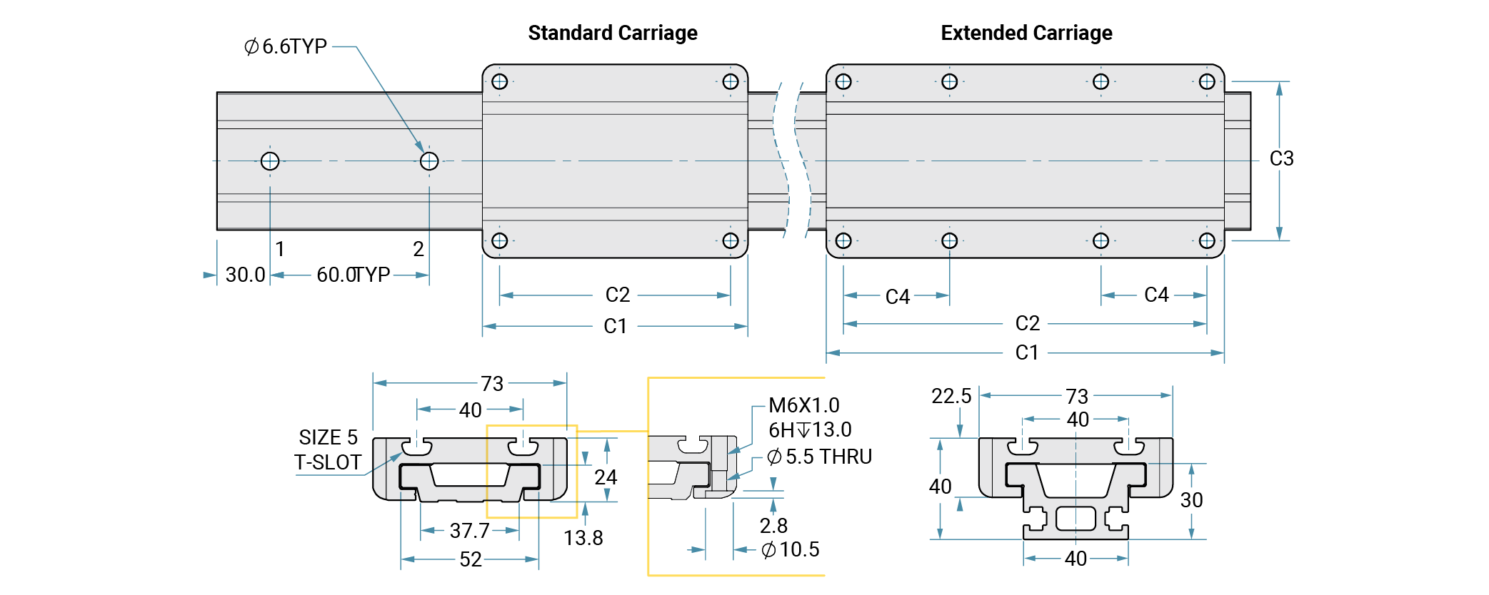
Notes:
- Default end to first hole is 30 mm.
- 60 mm hole spacing provided for higher moment capacity.
For low moment applications, every other hole may be used.
| Carriage Part # | Standard Carriage mm |
||||
|---|---|---|---|---|---|
| C1 | C2 | C3 | C4 | lb (kg) | |
| UGA040C-0x1xxx | 100 | 87 | 60 | N/A | 0.504 (0.23) |
| Extended Carriage | |||||
| UGA040C-1x1xxx | 150 | 137 | 60 | 40 | 0.750 (0.34) |
| UGA040C-2x1xxx | 200 | 187 | 60 | 60 | 1.014 (0.46) |
1 N=0.2248 lbf 1 N-m = 0.7376 ft.-lb
T-Nut Info
| Part No. | Part No. • Size |
|---|---|
| UGA and UGT | 6100443 • M5 x 0.8 |
Static Loads Data
The numbers below are for guides only in a static condition. The drive mechanism selected (lead screw, ball screw, cylinder, etc.) becomes the limiting factor when calculating maximum load and speed capacities. The user is responsible for determining the maximum capacity for the complete system based on the manufacturer’s data for their drive configuration.
| Size | Fz MAX Load lb. |
Fz MAX Load N |
Fz Inverted MAX Load lb. |
Fz Inverted MAX Load N |
|---|---|---|---|---|
| UGA040C-0x1xxx | 1843 | 8200 | 607 | 2700 |
| UGA040C-1x1xxx | 1483 | 6600 | 607 | 2700 |
| UGA040C-2x1xxx | 1101 | 4900 | 607 | 2700 |
| Size | Fy lb |
Mx in/lb |
My in/lb |
Mz in/lb |
Fy N |
Mx Nm |
My Nm |
Mz Nm |
|---|---|---|---|---|---|---|---|---|
| UGA040C-0x1xxx | 1101 | 1062 | 1505 | 1505 | 4900 | 120 | 170 | 170 |
| UGA040C-1x1xxx | 1281 | 1062 | 2567 | 2567 | 5700 | 120 | 290 | 290 |
| UGA040C-2x1xxx | 1371 | 1062 | 2567 | 2567 | 6100 | 120 | 290 | 290 |
Load/Moment Conversion
N = 4.45 x (lbs.)
N-m = 0.113 x (in.-lbs.)
Accessories
• Hand Brake
• Felt Wick*
*Warning: Felt wick is shipped without lubrication and requires the customer to add lubrication prior to operation of the carriage and rail.
Performance Ratings for Linear Motion
Plain bearings are rated by their limiting PV, which is a combination of load over a given surface area and the velocity.
| Bearing Material |
MAX. PV | MAX. P | MAX. V No Lubcrication |
|---|---|---|---|
| FrelonGOLD® | 20,000 (psi x ft./min.) or 0.7 N/mm2 x m/s |
3000 psi or 20.68 N/mm2 |
300 sfm or 1.524 m/s |
PV = The performance measurement of plain
bearings.
PV = P x V, where P = pressure (load) in psi
(kgf/cm2)
V = velocity (speed) in sfm
(m/min.)
PV Example: Load =
85 psi
Speed = 180 ft./min.
PV = 85 x 180 = 15,300 PV
Note: All three
parameters must be met by an application for the bearing to perform
properly.
Note: FrelonGOLD® bearing material coefficient of
friction is 0.125.
Cantilevered Loads
Binding of the carriage will occur if the 2:1 ratio for cantilevered loads and drive forces is exceeded. This principle is not load or force dependent. It is a product of the coefficient of frictions associated with plain bearings. Contact factory or website for additional information.

Uni-Guide
Product Overview
Uni-Guide reduces bulky part count with its two-piece assembly, simplifying integration into both new and existing applications. Accompanied by PBC Linear's FrelonGOLD® liner, Uni-Guide facilitates smooth, maintenance-free travel throughout the life of the system. Designed to thrive in challenging environments, UniGuide offers best-in-class linear motion performance.
Features and Benefits
• Ceramic coated, aluminum rail and anodized carriage
• Self-lubricating,
maintenance-free FrelonGOLD Liner
• The two-piece assembly makes for a quick and
easy integration while also eliminating the need for alignment in both new and
existing applications
• Excels in demanding extremes including temperature, heavy
particulates, washdown and extreme vibration
• No rolling elements, eliminating
possibility of catastrophic failure
• Easy drop-in unit – no alignment
necessary
• Slide sizes ranging from 75, 100, and 125 mm
• Continuous lengths
up to 10 feet (3,048 m)
• Standard cut-to-length rails and carriage assemblies
Accessories
• Hand brake
• Hand crank
• NEMA 17, 23, and 34 motor mount (driven systems)
Applications
• Automation & assembly line gripper
• Medical & laboratory equipment
•
Heavy duty vise
• Audio/visual display mounts
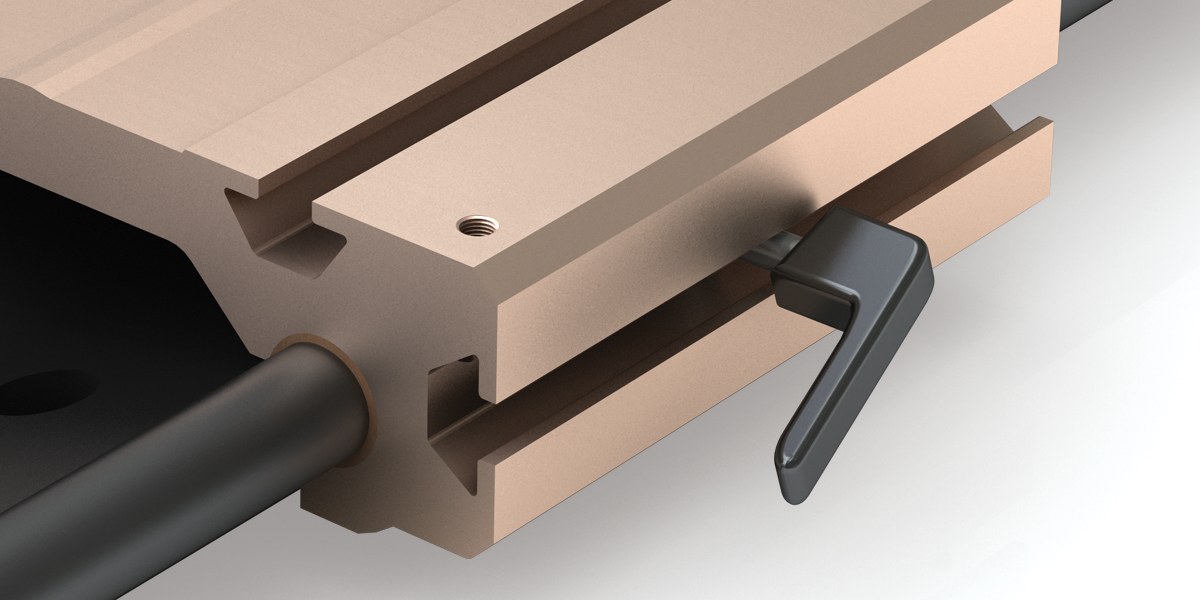
Hand Brake
Ordering Information
Carriage and Rail Assembly
| Series | Carriage Options | Nominal Size | Carriage Options | Overall Rail Length | Number of Carriages | ||
| D | XXX | - | XXX.XXX | - | X | ||
SeriesD - Standard Uni-Guide Carriage OptionsNo Entry - Standard Carriage L - Extended Length Carriage Nominal Size075 mm, 100 mm, 125 mm - Based on mm from shaft center-to-center Carriage OprionsNo Entry - None CHB - Hand Brake Overall Rail LengthLength
of Rail in Inches xxx.xxx (EX: 6" = 006.000) Number of Carriages
|
Note: Specify Y-dimension (hole to end) at time of order.
Dimensions
Standard Inch Series With No Drive Mechanism Inches
| Part Number |
R | R1 | R2 | X | R4 Bolt Size |
Y | H | C | C1 Standard |
C2 Standard |
C1 Extended |
C2 Extended |
C3 | C4 Bolt Size |
M | M1 | L Max-feet |
|---|---|---|---|---|---|---|---|---|---|---|---|---|---|---|---|---|---|
| D075 | 2.95 | 2.0 | 0.75 | 4 | 1/4 | 2 | 1.625 | 4.6 | 3.5 | 3.00 | 4.5 | 4.00 | 4.00 | 10-32 | 2.60 | 0.819 | 10 |
| D100 | 3.94 | 2.6 | 1.00 | 6 | 5/16 | 3 | 2.125 | 6.1 | 4.5 | 3.75 | 6.0 | 5.25 | 5.25 | 1/4-20 | 3.50 | 1.020 | |
| D125 | 4.92 | 3.3 | 1.25 | 3/8 | 3 | 2.625 | 7.6 | 6.0 | 5.25 | 7.5 | 6.75 | 6.75 | 5/16-18 | 4.33 | 1.300 |
Carriage Types
| Part No. | Drill | Depth | Tap | Depth |
|---|---|---|---|---|
| D075-xxx | 0.159 | 0.534 | 10-32 | 0.440 |
| D100-xxx | 0.201 | 0.750 | 1/4-20 | 0.500 |
| D125-xxx | 0.257 | 5/16-18 | 0.625 |
T-Slot Information Inches
| Part No. | T | T1 | T2 | Part No. • Size |
|---|---|---|---|---|
| D075-xxx | 0.590 | 0.256 | 0.236 | 6100435 • M6 x 1.0 |
| D100-xxx | 0.661 | 0.319 | 0.268 | 6100436 • M8 x 1.25 |
| D125-xxx |
Rail Ф Approximate
| D075 | 0.470 = 12 mm |
| D100 | 0.630 = 16 mm |
| D125 | 0.820 = 22 mm |
Rail Straightness
| ±.002"/ft |
|---|
Weight
| Part No. | Rail Per Inch lb. |
Standard Carriage |
Extended Carriage lb. |
|---|---|---|---|
| D075-xxx | 0.19 | 0.98 | 1.26 |
| D100-xxx | 0.32 | 2.12 | 2.82 |
| D125-xxx | 0.48 | 4.56 | 5.70 |
Static Loads Data
The numbers below are for guides only in a static condition. The drive mechanism selected (lead screw, ball screw, cylinder, etc.) becomes the limiting factor when calculating maximum load and speed capacities. The user is responsible for determining the maximum capacity for the complete system based on the manufacturer’s data for their drive configuration.
| Size | Fz MAX Load lb. |
Fz MAX Load N |
Fz Inverted MAX Load lb. |
Fz Inverted MAX Load N |
|---|---|---|---|---|
| D075 | 500 | 2224 | 125 | 556 |
| D100 | 750 | 3336 | 190 | 845 |
| D125 | 1000 | 4448 | 250 | 1112 |
| Size | Fy lb |
Mx in/lb |
My in/lb |
Mz in/lb |
Fy N |
Mx Nm |
My Nm |
Mz Nm |
|---|---|---|---|---|---|---|---|---|
| D075 | 250 | 340 | 340 | 350 | 1112 | 38 | 38 | 40 |
| D100 | 375 | 650 | 650 | 730 | 1668 | 73 | 73 | 82 |
| D125 | 500 | 1200 | 1200 | 1225 | 2224 | 136 | 136 | 138 |
Load/Moment Conversion
N = 4.45 x (lbs.)
N-m = 0.113 x (in.-lbs.)

Performance Ratings for Linear Motion
Plain bearings are rated by their limiting PV, which is a combination of load over a given surface area and the velocity.
| Bearing Material |
MAX. PV | MAX. P | MAX. V No Lubcrication |
|---|---|---|---|
| FrelonGOLD® | 20,000 (psi x ft./min.) or 0.7 N/mm2 x m/s |
3000 psi or 20.68 N/mm2 |
300 sfm or 1.524 m/s |
PV = The performance measurement of plain
bearings.
PV = P x V, where P = pressure (load) in psi
(kgf/cm2)
V = velocity (speed) in sfm
(m/min.)
PV Example: Load =
85 psi
Speed = 180 ft./min.
PV = 85 x 180 = 15,300 PV
Note: All three
parameters must be met by an application for the bearing to perform
properly.
Note: FrelonGOLD® bearing material coefficient of
friction is 0.125.
Cantilevered Loads
Binding of the carriage will occur if the 2:1 ratio for cantilevered loads and drive forces is exceeded. This principle is not load or force dependent. It is a product of the coefficient of frictions associated with plain bearings. Contact factory or website for additional information.

DRIVEN SYSTEMS: Mini-Rail

Product Overview
The lead screw driven Mini-Rail (MR-LS) system maintains all of the great features and benefits of Mini-Rail. The system is a fully interchangeable and economical solution to industry standard linear guides, and contains no rolling elements which avoids catastrophic failure.
Features and Benefits
- Right hand rolled thread
- 304 stainless steel screw with PTFE coating
- Self-lubricating Polyacetal, anti-backlash nut
- Lengths up to 640 mm
- Eight (8) leads available
Accessories
- NEMA 17 motor mount kit
- Hand brake
- Knob
Dimensions
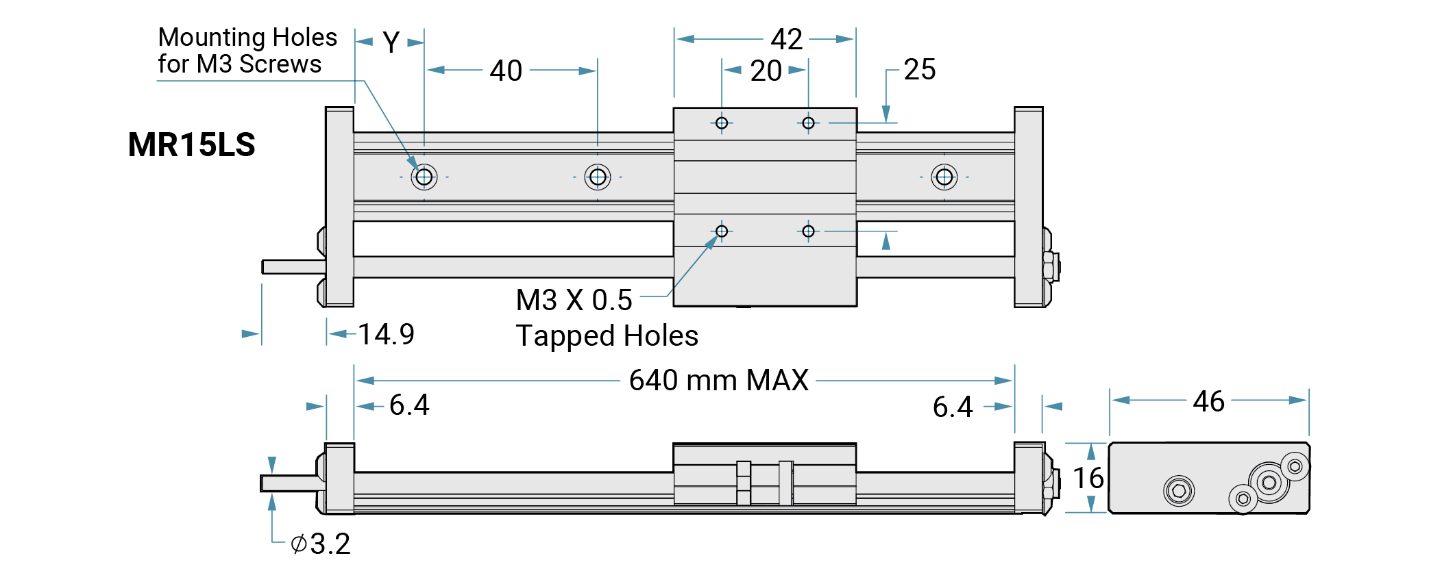
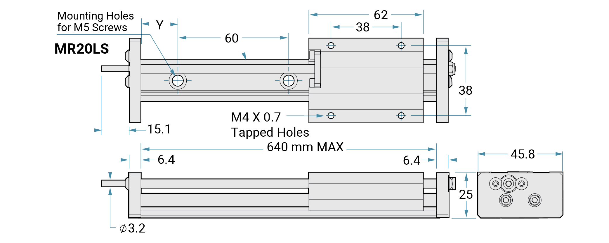
Note: Maximum length for lead screw driven MR is 640
mm
Note: Specify Y dimension (First Hole Offset - FHO) at time
of order
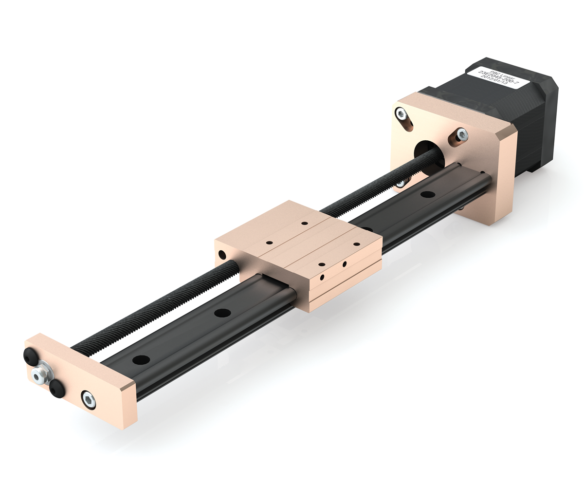
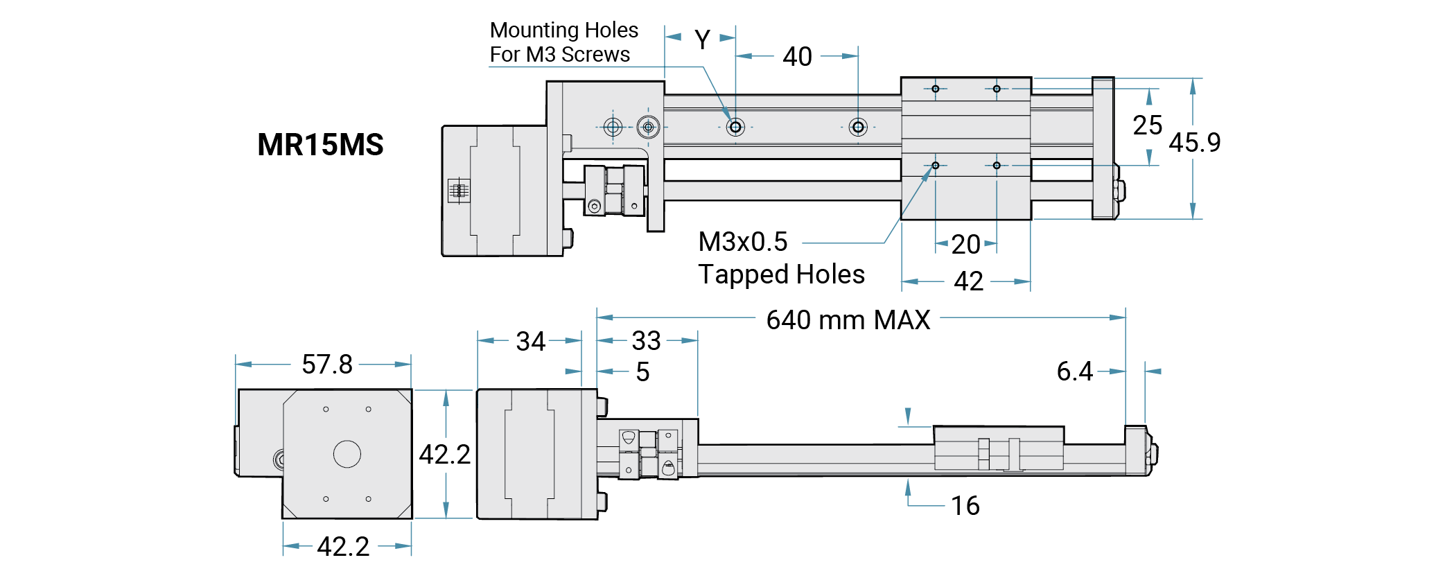
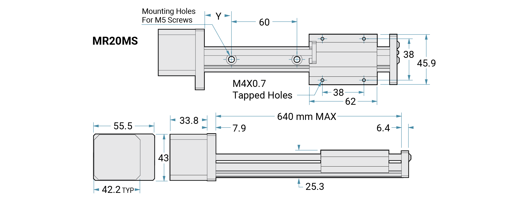
Product Overview
The Lead Screw Driven Mini-Rail with the attached motor brings another great feature forward in linear motion. Also equipped with all the great features of Mini-Rail, this low cost option is equipped with a high torque stepper motor (NEMA 17).
Features and Benefits
• Low cost
• High torque single stack stepper motor 42 mm (NEMA 17)
• Robust
design - outstanding reliability
• 304 stainless steel screw with PTFE
coating
• Fewer parts - less maintenance
• Integral screw for MR20 (coupling
used for MR15)
• Ball bearing supports in the end blocks
• Preloaded
Polyacetal, anti-backlash nut
• Lengths up to 640 mm
• Eight (8) leads
available
Dimensions
Ordering Information
Lead Screw Driven
| Mini-Rail | Nominal Size of Base in mm | Lead Screw | Length of Rail in mm | Screw Lead Option | Driving Mechanism | Mechanical Brake | Number of Carriages |
| MR | XX | LS | XXX | XX | XX | XX | X |
Mini-RailMR - Mini-Rail Nominal Size of Base in mm15 mm 20 mm Lead ScrewLS - Lead Screw Length of Rail in mmCut to length (Max. of 64Ø mm) Screw Lead OptionAH - 01 mm (0.039 in.) AG - 02 mm(0.079 in.) AR - 04 mm (0.157 in.) AX - 05 mm (0.197 in.) BG - 06 mm (0.236 in.) BH - 08 mm (0.315 in.) AJ - 10 mm (0.394 in.) BD - 12 mm (0.472 in.) Driving MechanismØØ - No knob SK - With screw knob 17 - NEMA 17 motor mount* Mechanical BrakeØØ - No Brake BL - With brake lever mounted on carriage Number of Carriages1 - One
carriage |
Note: Coupling not included; PBC Linear Recommends R+W EKL2 Coupling or equivalent. Actuator requires 3.18 mm (0.125") bore)
Lead Screw Driven with Motor
| Mini-Rail | Nominal Size of Base in mm | Lead Screw | Length of Rail in mm | Screw Lead Option | Nominal Size of Stepper Motor | Number of Carriages | |
| MR | XX | MS | XXX | XX | M42 | 00 | X |
Mini-RailMR - Mini-Rail Nominal Size of Base in mm15 mm 20 mm Lead Screw
Length of Rail in mmCut to length (Max. of 64Ø mm) Screw Lead OptionAH - 01 mm (0.039 in.) AG - 02 mm(0.079 in.) AR - 04 mm (0.157 in.) AX - 05 mm (0.197 in.) BG - 06 mm (0.236 in.) BH - 08 mm (0.315 in.) AJ - 10 mm (0.394 in.) BD - 12 mm (0.472 in.) Nominal Size of Stepper MotorM42 - 42 mm (NEMA 17) Number of Carriages1 - One
carriage |
Note: Specify Y-dimension (hole to end) at time of order.
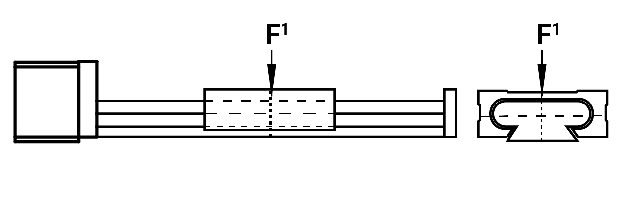
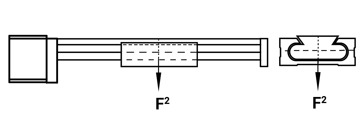
Static Loads Data
The numbers below are for rails in a static condition. Refer to the calculations below to establish dynamic parameters.
| F1 N |
|
|---|---|
| Size 15 | Size 20 |
| 3114 | 6005 |
| F2 N |
|
|---|---|
| Size 15 | Size 20 |
| 356 | 578 |
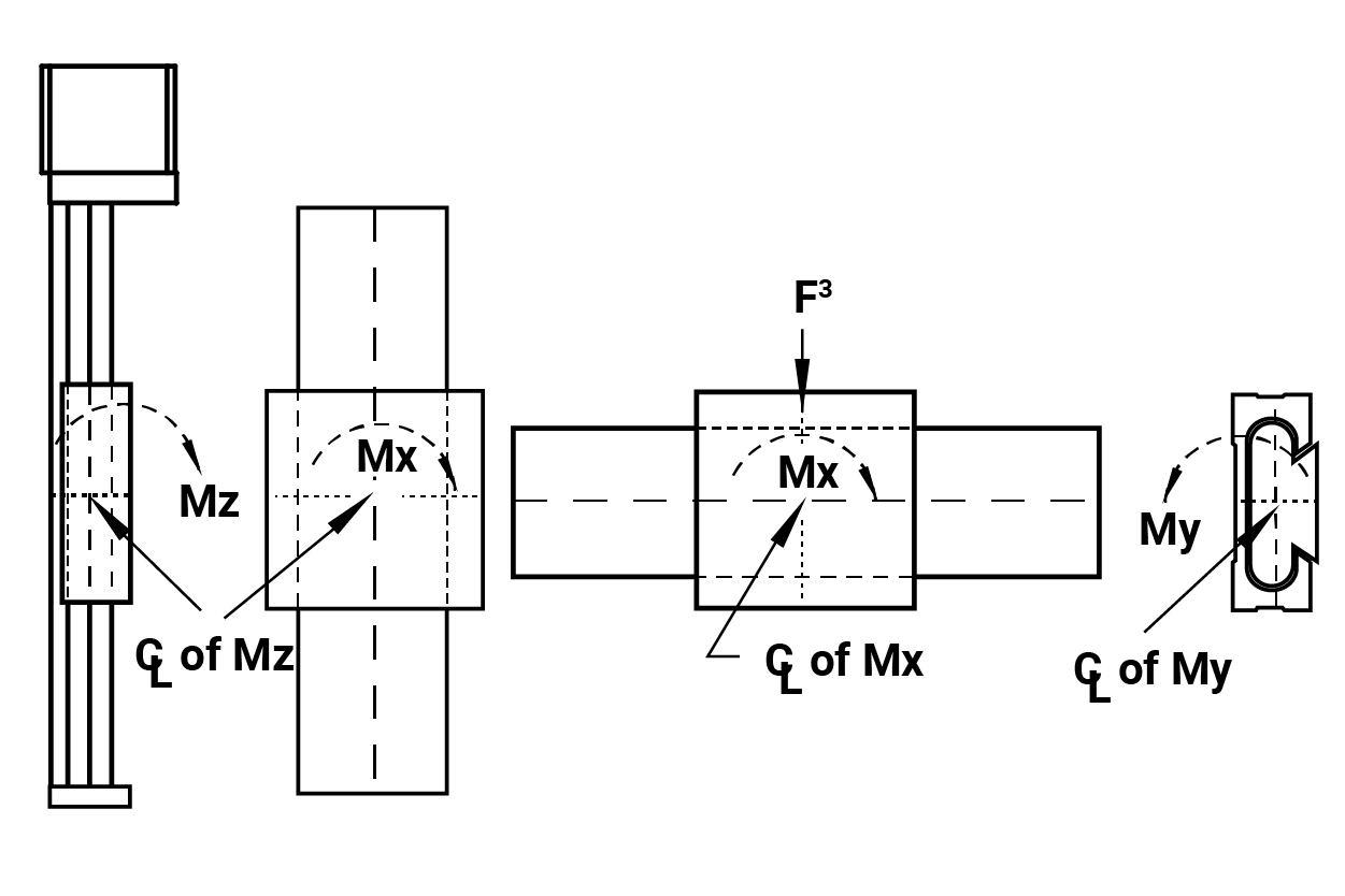
| F3 N-m |
Mx N-m |
My N-m |
Mz N-m |
|---|---|---|---|
| 1112 | 24.9 | 14.7 | 14.7 |
Size 17 stepper motor with 6 mm (0.236") screw
Performance Ratings for Linear Motion
Plain bearings are rated by their limiting PV, which is a combination of load over a given surface area and the velocity.
| Bearing Material |
MAX. PV | MAX. P | MAX. V No Lubcrication |
|---|---|---|---|
| FrelonGOLD® | 20,000 (psi x ft./min.) or 0.7 N/mm2 x m/s |
3000 psi or 20.68 N/mm2 |
300 sfm or 1.524 m/s |
PV = The performance measurement of plain
bearings.
PV = P x V, where P = pressure (load) in psi
(kgf/cm2)
V = velocity (speed) in sfm
(m/min.)
Note: All three parameters must be met by an
application for the bearing to perform properly.
Cantilevered Loads
Binding of the carriage will occur if the 2:1 ratio for cantilevered loads and drive forces is exceeded. This principle is not load or force dependent. It is a product of the coefficient of frictions associated with plain bearings. Contact factory or website for additional information.

Load/Moment Conversion
N = 4.45 x (lb.)
N-m = 0.113 x (in-lb.)
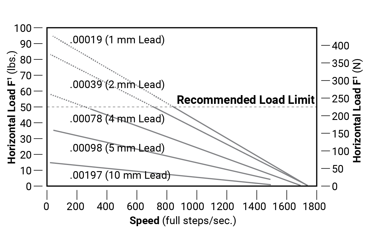
| Lead | Lead Code | Linear Travel per Step | |
|---|---|---|---|
| mm | Inch | ||
| 1 mm | AH | 0.005 | 0.000197 |
| 2 mm | AG | 0.010 | 0.000394 |
| 4 mm | AR | 0.020 | 0.000787 |
| 5 mm | AX | 0.025 | 0.000984 |
| 6 mm | BG | 0.030 | 0.001181 |
| 8 mm | BH | 0.040 | 0.001575 |
| 10 mm | AJ | 0.050 | 0.001969 |
| 12 mm | BD | 0.060 | 0.002362 |
Note: 1.8° = 200 steps per revolution
DRIVEN SYSTEMS: Uni-Guide
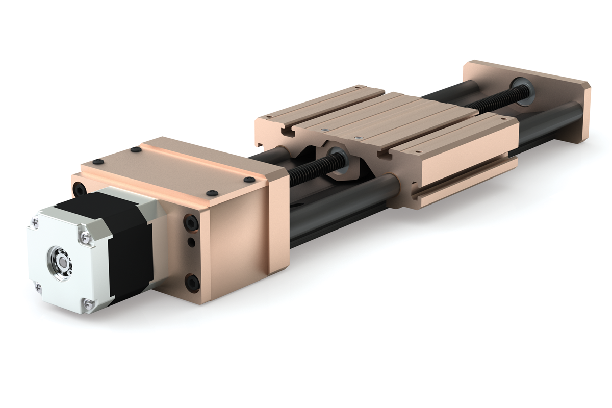
Product Overview
The Uni-Guide driven system offers all the same best-in-class linear motion performance advantages as the standard Uni-Guide. The reduced part count will continue to simplify assembly and integration, and will facilitate smooth, maintenance-free travel throughout the life of the system.
Features and Benefits
• Thrives in the most challenging environments
• Self lubricating FrelonGOLD®
liner
• Offers three (3) slide sizes: 75, 100, 125 mm
• Standard cut-to-length
rail & carriage assemblies
• Easy drop-in unit - no alignment necessary
Accessories
• NEMA 17, 23 and 34 motor mount kit
• Hand brake (components)
• Hand crank
(components)
Drive Shafts

Ordering Information
| Series | Carriage Options | Nominal Size | Drive Options | Drive Mounting Options | Overall Rail Length | Number of Carriages | ||
| D | XXX | M | - | XXX.XXX | - | X | ||
SeriesD - Standard Uni-Guide Carriage OptionsNo Entry - Standard Carriage L - Extended Length Carriage Nominal Size075 mm - Based on mm from shaft center-to-center 100 mm - Based on mm from shaft center-to-center 125 mm - Based on mm from shaft center-to-center Drive OptionsM - Right Hand Lead Screw with Standard Pitch M1 - Right Hand Lead Screw with Optional Pitch Notes: Screw options require attaching collar. Call the factory for other optional drive mechanism. Drive Mounting OptionsNo Entry - H - Hand Crank N - NEMA Standard Motor Mount HB - Handbrake (requires handcrank and screw) HCHB - Hand Crank and Carriage Brake CHB - Carriage Handbrake H2CHB - CHB option with two brakes Overall Rail LengthLength
of Rail in Inches xxx.xxx (EX: 6" = 006.000). Number of Carriages |
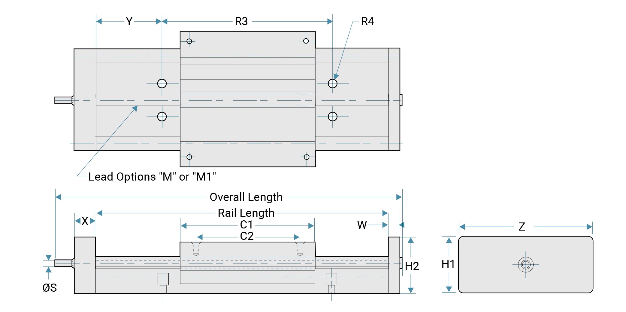
Dimensions
| Part No. |
Nominal Screw Dia. |
M Standard Lead |
M1 Optional Lead |
C1 Standard |
C2 Standard |
C1 Extended |
C2 Extended |
C3 | S in |
Y in |
R3 in |
R4 in |
W in |
X in |
Z in |
H1 in |
H2 in |
|---|---|---|---|---|---|---|---|---|---|---|---|---|---|---|---|---|---|
| D075 | 10 mm | 6 mm | 12 mm | 3.5 | 3.00 | 4.5 | 4.00 | 4.00 | 0.187 | 2 | 4 | 1/4 | 0.375 | 0.625 | 3.42 | 1.75 | 1.625 |
| D100 | 12 mm | 6 mm | 12 mm | 4.5 | 3.75 | 6.0 | 5.25 | 5.25 | 0.314 | 3 | 6 | 5/16 | 0.500 | 0.625 | 3.42 | 1.75 | 1.625 |
| D125 | 16 mm | 5 mm | 12 mm | 6.0 | 5.25 | 7.5 | 6.75 | 6.75 | 0.314 | 3 | 6 | 3/8 | 0.500 | 1.000 | 5.78 | 3.5 | 2.500 |
Note: Optional leads may be available - consult factory. Specify Y
dimension (hole to end) at time of order.
Stroke = Rail Length - Carriage Length
- Overtravel Idle End - Over Travel Drive End.
Hand Brake Inches

| Part No. | W | D | H2 |
|---|---|---|---|
| D075HB | 3.42 | 1.74 | 3.4 |
| D100HB | 4.57 | 2.50 | 4.3 |
| D125HB | 5.79 | 3.47 | 4.7 |
Hand Crank

| Part No. | P | H |
|---|---|---|
| D075XH | 2.31 | 1.75 |
| D100XH | 2.31 | 2.25 |
| D125XH | 2.31 | 3.25 |
Motor Mount Attachment

| Part No. | NEMA Motor | B | E | D |
|---|---|---|---|---|
| D075XN | NEMA 17 | 2.0 | 1.81 | 3.25 |
| D100XN | NEMA 23 | 2.5 | 1.81 | 3.25 |
| D125XN | NEMA 34 | 3.5 | 2.3 | 4.25 |
Static Loads Data
The numbers below are for guides only in a static condition. The drive mechanism selected (lead screw, ball screw, cylinder, etc.) becomes the limiting factor when calculating maximum load and speed capacities. The user is responsible for determining the maximum capacity for the complete system based on the manufacturer’s data for their drive configuration.
| Size | Fz MAX Load lbs |
Fz MAX Load N |
Fz Inverted MAX Load lbs |
Fz Inverted MAX Load N |
|---|---|---|---|---|
| D075 | 500 | 2224 | 125 | 556 |
| D100 | 750 | 3336 | 190 | 845 |
| D125 | 1000 | 4448 | 250 | 1112 |
Performance Ratings for Linear Motion
Plain bearings are rated by their limiting PV, which is a combination of load over a given surface area and the velocity.
| Bearing Material |
MAX. PV | MAX. P | MAX. V No Lubcrication |
|---|---|---|---|
| FrelonGOLD® | 20,000 (psi x ft./min.) or 0.7 N/mm2 x m/s |
3000 psi or 20.68 N/mm2 |
300 sfm or 1.524 m/s |
PV = The performance measurement of plain
bearings.
PV = P x V, where P = pressure (load) in psi
(kgf/cm2)
V = velocity (speed) in sfm
(m/min.)
PV Example: Load = 85 psi
Speed =
180 ft./min.
PV = 85 x 180 = 15,300 PV
Note: All
three parameters must be met by an application for the bearing to perform
properly.
Note: FrelonGOLD® bearing material coefficient of
friction is 0.125.
Load/Moment Conversion
N = 4.45 x (lbs.)
N-m = 0.113 x (in.-lbs.)
Cantilevered Loads
Binding of the carriage will occur if the 2:1 ratio for cantilevered loads and drive forces is exceeded. This principle is not load or force dependent. It is a product of the coefficient of frictions associated with plain bearings. Contact factory or website for additional information.

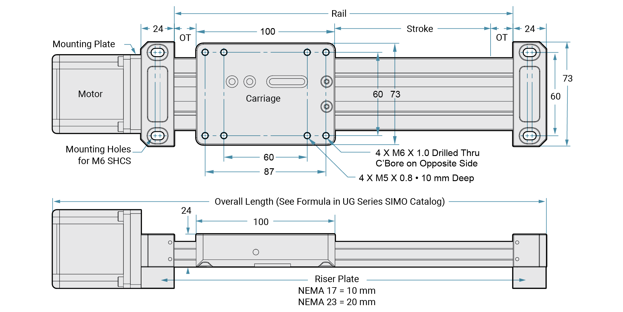
DRIVEN SYSTEMS: Low Profile Uni-Guide
PBC Linear offers a Low Profile Uni-Guide driven system through the SIMO Series line of products. This process has revolutionized traditional machining. The SIMO process uses synchronized cutters, eliminating built-in extrusion variances by machining all critical edges concurrently. This ensures tight tolerances, limited variance and a remarkably straight and repeatable surface at negligible additional cost.
Product Overview
- Utilizes a self-lubricating and maintenance free nut
- Standard fixed nut or Constant Force anti-backlash nut available
- Lead screw material:
- 10 mm diameter
- 300 series stainless steel with PTFE coating
- 1, 2, 5, 10, 16 mm leads most common
- Other leads available – consult factory
- Ideal for a broad range of applications such as kiosks, assembly, automation, medical, and laboratory
Features and Benefits
- Standard integrated screw stepper motors
- 42 mm (NEMA 17)
- 56 mm (NEMA 23)
- Integrated lead screw eliminates components and tolerance stack-ups
- Improves rigidity and performance
- Reduces system cost
Accessories
- Hand knobs – for manual positioning or applications that require precision adjustment
- Riser blocks
- Toe clamps and t-nuts
- Brake knobs
- Optional motor mounts
Ordering Information
| SIMO Series | Rail Type | Rail Width | Order Type | Carriage Type | Options | Rail Length | Drive Type | Drive End Option | Motor Option | Lead | Nut | Accuracy | Other Options | |||||
| UG | A | 040 | D | - | A1 | X | - | XXXX | - | LS | X | XX | - | XX | X | 1 | - | 0 |
SIMO SeriesUG - SIMO Uni-Guide Rail TypeA - Low Profile Rail Width40 mm Order TypeD - Driven Carriage TypeA1 -
GST with FrelonGOLD Options0 - No Options 1 - Carriage Brake 2 - Lube 3 - Both Rail Length1500 mm max Consult Factory for Longer Lengths Drive TypeLS - Lead Screw Drive End Options1 - Shaft 2 - Knob 3 - PBC Integrated Motor Screw Motor Option00 - No Motor/Stub Shaft Only A1 - 42 mm (N17) Single Stack A2 - 42 mm (N17) Double Stack A3 - 42 mm (N17) Triple Stack B4 - 56 mm (N23) Single Stack B5 - 56 mm (N23) Double Stack B6 - 56 mm (N23) Triple Stack ZZ - No Motor/Stub Shaft with Assembled Motor Mount* Lead (mm)AF - 16 AJ - 10 AX - 5 AG - 2 AH - 1 *Consult Factory for Other Leads Nut1 - Standard 2 - Anti-Backlash Accuracy1 - Class 10 Other Options
|
Dimensions
Plain Bearings • Frelon® Material
Product Overview
- Frelon liner is bonded to the carriage at the molecular level, which transfers the load and dissipates heat buildup
- No metal-to-metal contact provides a smoother, quieter running assembly
- Anodized aluminum prevents rust and corrosion
- Maintenance free, smooth and quiet operation - plus long life
- No rolling elements, no catastrophic failure
Frelon Liner Materials
Frelon liners are compounds of PTFE and fillers developed for improved performance over other bearings. They provide low wear, low friction, self-lubrication, and high strength.
PTFE Features:
- Self-lubricating, runs without added lubricant
- Embeddability of hard particulate
- Wide temperature range (-400°F/+400°F) (-240°C/+204°C)
- Chemically inert
- Vibration damping and shock resistant
Filler Benefits
• High load capacity
• High strength
• Low wear rate versus other materials

Load Capacity of Liner
| Bearing Material | Static Load Capacity |
|---|---|
| FrelonGOLD® | 3000 psi or 210.9 kgf/cm2 |
- Frelon liner can carry from 4 to 20 times the load capacity of a ball bearing
- Allows the engineer to maintain performance in a smaller designed package
- Shock loads and vibration are absorbed
Speed Characteristics
| Bearing Material |
No Lube Continuous Motion |
No Lube Intermittent Motion |
With Lubrication* |
|---|---|---|---|
| FrelonGOLD | 300 sfm | 825 sfm | 825 sfm |
| 60 in/sec. | 165 in./sec. | 165 in./sec. | |
| 1.524 m/sec. | 4.19 m/sec. | 4.19 m/sec. |
Exceeding these speeds causes frictional heat and accelerates liner
wear.
*Depending on the lubrication used, loads, and frequency of
continuous or intermittent motion, speeds can be in excess of the numbers
shown.
Performance Ratings (for Linear Motion)
Plain bearings are rated by their limiting PV which is a combination of load over a
given surface area and the velocity.
PV = The performance
measurement of plain bearings
PV = P x V where P = pressure
(load) in psi (kgf/cm2)
V = velocity (speed) in sfm
(m/min.)
Note: All 3 parameters must be met by an
application for the bearing to perform properly.
| Bearing Material |
MAX. "PV" | MAX. "P" | MAX. "V" No Lubrications |
|---|---|---|---|
| FrelonGOLD | 20,000 (psi) x ft./min.) or 430 (kgf/cm2 x m/min.) |
3000 psi or 210.9 kgf/cm2 |
300 sfm or 91.44 m/min. |

Transfer Process of Liner to Rail
The interaction of Frelon material and the rail creates a natural, microscopic
transfer of Frelon to the running surface. A thin film is deposited on the rail, and
the valleys in the surface finish are filled in with Frelon material during the
initial break-in period. This transfer creates the self-lubricating condition of
Frelon riding on Frelon.
This break-in period will vary depending on several
criteria:
- Preparation of the rail prior to installation: It is best to clean the rail with a 3-in-1 type oil before installing the carriages. This ensures that the surface will receive a full transfer of material.
- Speed, load, and length of stroke specific to the application: Typically, the initial transfer process will take approximately 50-100 strokes of continuous operation. The running clearance on the bearing will increase an average of 0.0002" to 0.0005", depending on the length of the stroke and surface requiring the transfer.
- How often the rail is cleaned: If the rail is cleaned regularly, increased wear will be seen in the carriage. This is due to the transfer process being performed over and over again.
Do not repeatedly clean the rail with alcohol! This will remove the previously transferred material entirely and increase the wear to the carriage liner.
Frelon Transfer Process

At break-in, Frelon deposits a microscopic film on the shaft and fills the valleys in the surface finish creating a Frelon-on-Frelon running condition that is true self-lubrication.
Lubrication
- Reduce friction up to 50%.
- Minimize wear of liner.
- Reduce heat buildup allowing greater speeds. Actual speeds achieved are dependent on type of lubricant and frequency of application.
- Aid in cleaning the rail for a proper transfer process. Initial lubrication is strongly recommended.

Chemical Resistance
The bearing surface of the rail can stand up to harsh environments and will provide
excellent performance in a submerged condition.
FrelonGOLD –
the fillers in the material can be attacked by deionized water and other harsh
chemicals.
Anodized Aluminum (Standard) – good chemical
resistance in most industrial applications.

Temperature
GST linear guides can operate in a wide range of temperatures (-400°F/+400°F) (-240°C
/+204°C).
• Maintains the same performance characteristics
• The thin
liner allows heat to dissipate through the carriage
Thermal Expansion
The standard bearing clearance options are designed for use in most industrial
applications.
For temperatures below 0° F, the Standard I.D. is
recommended.
For extreme high temperatures, Mini-Rail offers the Compensated
I.D. which is recommended for the increased running clearance.
CAUTION: It is always best to inspect actual size at extreme temperatures to insure proper running clearance.
Vacuums/Outgassing/Cleanrooms
Due to self-lubrication, low outgassing, and a minimum of particulate (buildup), the
carriages are excellent in clean rooms and vacuums.
Testing has been done on
the Frelon® materials in accordance with ASTM E-595-90 with acceptable maximums of
1.00% TML and 0.10% CVCM.
| Material | %TML | %CVCM |
|---|---|---|
| FrelonGOLD | 0.00 | 0.00 |
TML = Total Mass Loss
CVCM = Collected Volatile
Condensable Materials
Temperature Extremes

Washdown and Submerged Applications
GST linear guides will provide excellent performance in a washdown or submerged
condition.
The linear guide will employ the fluid as a lubricant showing
increased velocities and wear life. Oils and non-salt water are especially
effective.
Note: Please contact manufacturer before
utilizing units with the FrelonGOLD liner for submerged applications.

Plain Bearings • Types & Effects of Lubrication
Types and Effects of Lubrication
Lubrication is any outside technique used for reducing the friction, wear, or both of
a bearing. Proper lubrication of carriages is critical. Evaluate
lubrication needs on an application by application basis to determine whether or not
it should be used at all, what type is needed, and how it is applied. Below are some
criteria on which to base the lubricant decision:
Do not use WD40™,
PTFE sprays, or other oils, greases, or sprays that contain fluorocarbons or
silicone. In testing, these lubricants have proven to cause long-term stick-slip
problems with the Frelon lined carriages. They tend to become a gummy substance that
ultimately increases friction.
WD40™ is a registered trademark of the WD40
Corporation.
Recommended Lubricants:
- Way lube oils
- Lightweight oils
- 3-in-1 type oils
- Lightweight petroleum based greases
Using Oils with GST Units
DO NOT USE ANY TYPE OF MOTOR OIL OR OILS WITH
ADDITIVES!
These types of oils work well short term, but quickly
become ineffective, and will cause stick-slip reactions. As a rule of thumb, the
less additives in the oil, the better the performance. Recommended oils are Mobil
Vactra #2 (a way lube oil) and any standard 3-in-1 oil. The 3-in-1 oils are
tremendous cleaning oils and are the best in preparing for a proper transfer of
teflon to the rail.
Grease Products
DO NOT USE A MOLY FILLED OR OTHER TYPE FILLED GREASES!
They
become like a lapping compound and increase wear dramatically.
Proper Use of Greases
Proper use of grease is critical for trouble-free operation. If a felt wick is
present, be sure it is removed because grease inserted into the carriage will cause
the wick to act like a brake.
Do not fill all of the running
clearance with grease!
The temptation is to treat it like a
rolling element and fill it until it weeps from the end. This will cause greater
friction and binding.
The rule of thumb for the carriage liner that “thin is
better” applies to the use of grease also.
If grease is used and does not work in
the application, it is possible to salvage the carriage with minimal work and to
continue to operate. Follow the steps below:
- If possible, remove the carriage from the rail, wipe the grease from the liner, use a 3-in-1 type oil to clean the excess remaining grease, and reinstall.
- If it is not possible to remove the carriage, wipe as much grease as possible away from the ends, then start to add a 3-in-1 type oil for cleaning the liner. If there is a Zerk hole, apply forced air to the carriage to speed the cleaning process and continue using oil lubrication.
Plain Bearings • Cantilevered Loads
Cantilevered Loads
- Maximum 2:1 ratio
- 1x = carriage separation on same rail
- 2x = distance from rail to load or force
Example: If 2x equals 10” then 1x must be at least
5”
Binding will occur if the 2:1 ratio is exceeded!
CAUTION: This principle is NOT load dependent! It is NOT due to edge loading. It is also NOT dependent on the driving force used! The carriages will bind whether hand or mechanically driven. This principle is a product of friction.

Working through the following equation will explain why this is a product of
friction:
\( P \) = force being applied
\( L \) =
distance out from rail that P is being applied
\( s \) = center to center spacing
of carriage
\( f \) = resultant force on carriage by rail
\( F \) = friction
force on each carriage
\( \mu \) = coefficient of friction (about .25 when not
moving)
Balance the moments:
\( f \cdot s = L \cdot P
\)
\( \displaystyle \frac{L}{s} = \frac{f}{P} \)
Compute friction
force:
\( F = f \cdot \mu \)
Note: Total friction
force pushing up is 2 * F. To lock up the slide, the total friction force must
be equal to (or greater than) P.
\( P = 2 \cdot F = 2 \cdot f \cdot
\mu \)
Substitute for P:
\( \displaystyle \frac{L}{s} =
\frac{f}{(2 \cdot f \cdot \mu)} = \frac{1}{(2 \cdot \mu)} \Rightarrow \frac{L}{s} =
\frac{1}{(2 \cdot \mu)}\)
Note: The forces drop out of the
equation
Assume static coefficient of friction is .25 (µ = .25) then
L / s = 2 That is the 2:1 ratio.
There may be other factors that add to the
braking effect, but the coefficient of friction is the main
cause.
Note: Proper lubrication can help to drop friction and extend
the 2:1 ratio.

Counterbalance
If holding the 2:1 ratio is not possible, one method of preventing binding problems
is using a counter balance.
Use the number of bearing pads or surfaces within
a carriage and determine spacing based on the length of the carriage.
For
efficient counter balances in horizontal applications, use this formula:
\( M \cdot Y = W \cdot Z \)
Note: To avoid problems when running without mass:
\( \displaystyle (M) \, Z = 1 - \frac{1}{2} s \)
W can be calculated. Load on bearing will be:
\( M + W \)
# of carriage
Example: \( 50 \cdot 24 = W \cdot Z \, (Z = 1 - \frac{1}{2} \cdot 6 = 9) \)
\( \displaystyle \frac{W = 50 \cdot 24 = 133 \, lb.}{9} \)
Load per bearing:
\( \displaystyle \frac{(50 + 133)}{4} = \text{45.75 lb. / bearing} \)
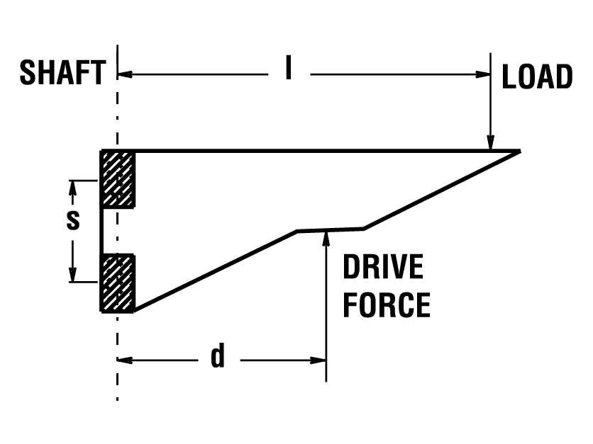
Cantilever Loads and Drive Force Location without Counterbalance
\( d \) = distance from shaft to Drive Force
\( l \) = distance from shaft to
the load center of gravity
\( s \) = center to center spacing of the carriage on
the rail (If non-self-aligning, then outside to outside distance should be
used.)
\( \displaystyle L = \frac{l}{s} \) = Load Force Ratio
\( \displaystyle
D = \frac{d}{s} \) = Drive Force Ratio
Hanging or “Top Heavy” Horizontal Applications with High Acceleration Rates:
If your application will have high acceleration forces, use this formula for the value of the Drive Force Ratio:
\( D = 0.8 \cdot L \cdot \sqrt{a} \) where a is acceleration in g’s.

General Rules:
- Drive Force Ratio (D) should never be larger than 2. A Drive Force Ratio (D) larger than 2 can cause the slide to lock up.
- Load Force Ratio (L) can be larger than 2, but as this ratio increases, the drive force required to move the slide increases dramatically. A Load Force Ratio (L) larger than 4 is not recommended.
- If the slide is occasionally operated unloaded, use the distance to the slide’s center of gravity as the distance to the load ( l ).
Vertical Applications
- If L is between 0 and 2, the lowest drive forces occur when the value of D is about 90% of L (D = .9 x L). However, D values between 0 and L will work fine.
- If L is between 2 and 4, use this equation: D = 4 - L
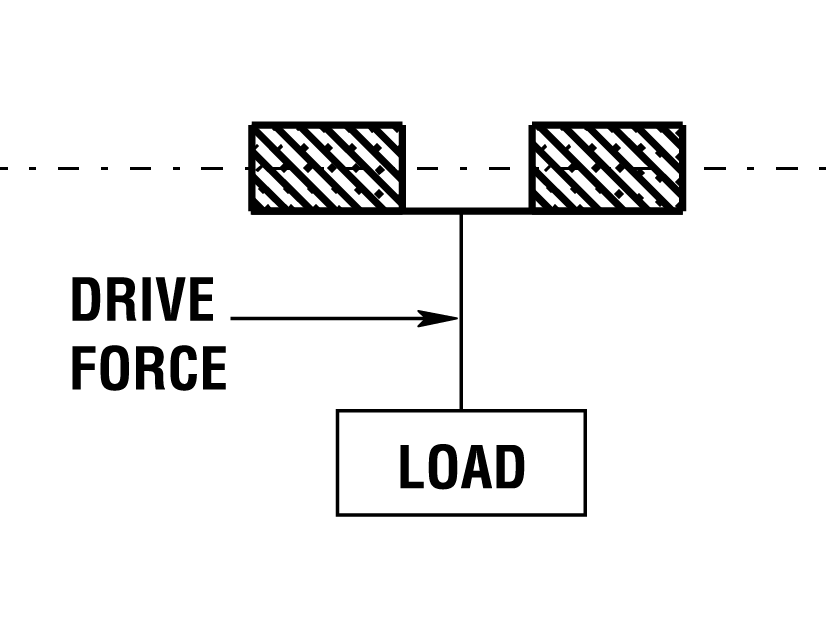
Horizontal Applications
For best results, the drive force should be applied as close to the shaft as possible no matter what the value of the Load Force Ratio (L) is.
Plain Bearing • Chemical Reaction Information
FrelonGOLD® material is a composite of PTFE and a bearing filler. The PTFE is
chemically inert. The chemical resistance shown in the chart below is defined by the
compatibility of the filler with the various chemicals.
The table is provided
as a reference only. The data given will be affected by factors such as temperature,
PV, degree of contact, strength of solution, etc. In each specific application, it
is always advisable to conduct specific testing to determine suitability of use.
This table only addresses general corrosion, NOT galvanic, SCC, or other types of
corrosion. Corrosion rates are at room temperature unless otherwise
noted.
Standard and hard coat data only apply when the coating is intact. If
the coating is worn through or damaged, an area of galvanic and pitting corrosion
will be created. Then use the bare aluminum data.
Gliding Surface Technology
products use aluminum alloy, which is known to have the best corrosion resistance of
the high strength aluminum alloys. The sulfuric bath anodizing and nickel acetate
sealing provide the best corrosion resistance available in anodized coatings. They
can withstand a rigorous 14-day exposure in a 5% salt spray solution at 96°F per
military specifications without significant damage. With the coating intact, it is
considered to be inert in most fluids with a pH value between 5 and 8. Hard coat
anodizing provides the same chemical resistance but is applied to a .002" thickness,
providing a more durable surface that will stand up to greater abuse. However, if
the coating is penetrated, the resistance is reduced.
Special stainless steel
components use AISI 316 stainless, which has superior resistance over 303, 304, 420,
440, 17-4PH, and most other common stainless grades. 316 is generally considered to
be the most corrosion resistant of conventional stainless
steels.
Note: This information was compiled for Pacific Bearing®
Company by Materials Engineering, Inc. of Virgil, IL. This specification
information is believed to be accurate and reliable, however, no liability is
assumed. Information is for reference only. User must test specific
applications.

Plain Bearing • Chemical Reaction Chart
| Performance | Wear | |
|---|---|---|
| E | Excellent | < 0.002” per year |
| G | Good | < 0.020” per year |
| S | Satisfactory | < 0.050” per year |
| U | Unsatisfactory | > 0.040” per year |
| Chemical | Frelon GOLD® |
Bare Aluminum |
Standard and Hard Coat Anodized Aluminum |
316 Stainless Steel |
|---|---|---|---|---|
| Acetic Acid, 20% | U | G | G | E |
| Acetone | G | E | E | E |
| Ammonia, Anhydrous | G | E | E | E |
| Ammonium Chloride, 10% | U | U | U | G |
| Ammonium Hydroxide, 10% | U | U | U | E |
| Ammyl Acetate (122°F / 50°C) | G | E | E | E |
| Barium Hydroxide | U | U | U | G |
| Beer | G | E | E | E |
| Boric Acid Solutions | G | E | E | G |
| Butane | G | G | G | G |
| Calcium Chloride, 20% | G | G | G | G |
| Calcium Hydroxide, 10% | G | G | G | G |
| Carbon Dioxide | G | E | E | G |
| Carbon Monoxide | G | E | E | E |
| Chlorine Gas, Dry | G | G | G | G |
| Chlorine Gas, Wet | U | U | U | U |
| Chromic Acid, 10% | U | G | E | E |
| Citric Acid, 5% | G | E | E | E |
| Ethyl Acetate | G | E | E | G |
| Ethyl Alcohol | G | E | E | G |
| Ethylene Glycol | G | E | E | G |
| Ferric Chloride, 50% | U | U | U | U |
| Formic Acid - Anhydrous | U | E | E | E |
| Gasoline, Unleaded | G | G | G | G |
| Hydrochloric Acid, 20% | U | U | U | U |
| Hydrochloric Acid, 35% | U | U | U | U |
| Hydrocyanic Acid, 10% | U | G | G | G |
| Hydrofluoric Acid - Dilute | U | U | U | U |
| Hydrofluoric Acid, 48% | U | U | U | U |
| Hydrogen | G | E | E | E |
| Hydrogen Peroxide - Dilute | U | E | E | G |
| Sea Water | G | G | E | G |
| Hydrogen Sulfide, Dry | U | G | E | E |
| JP-4 | G | G | G | G |
| Kerosene | G | G | G | G |
| Lacitic Acid, 10% | G | G | G | E |
| Magnesium Chloride, 50% | G | U | U | G |
| Mercury | U | U | U | E |
| Methyl Alcohol | G | G | G | G |
| Methyl Ethyl Ketone | G | G | G | G |
| Methylene Chloride | G | E | E | G |
| Mineral Oil | G | G | G | G |
| Naptha | G | G | G | G |
| Nitric Acid, 70% | U | U | U | E |
| Phosphoric Acid, 10% | U | U | U | E |
| Sodium Chloride | G | U | U | E |
| Sodium Hydroxide, 20% | G | U | U | G |
| Sodium Hypochlorite, 20% | U | G | G | U |
| Sodium Peroxide, 10% | U | G | G | G |
| Steam (see water) | - | - | - | - |
| Sulfur Dioxide, Dry | G | G | G | G |
| Sulfur Dioxide, Wet | U | U | U | G |
| Sulfur Trioxide | U | G | G | G |
| Sulfuric Acid, 50% | U | U | U | U |
| Sulfurous Acid | U | G | G | E |
| Toluene (122°F / 50°C) | G | E | E | E |
| Turpentine | G | G | E | E |
| Water, Demineralized | U | G | E | E |
| Water, Distilled | G | U | S | G |
| Water, Sewage | G | U | S | G |
| Xylene | G | G | G | G |
| Zinc Chloride Solutions | U | U | U | G |
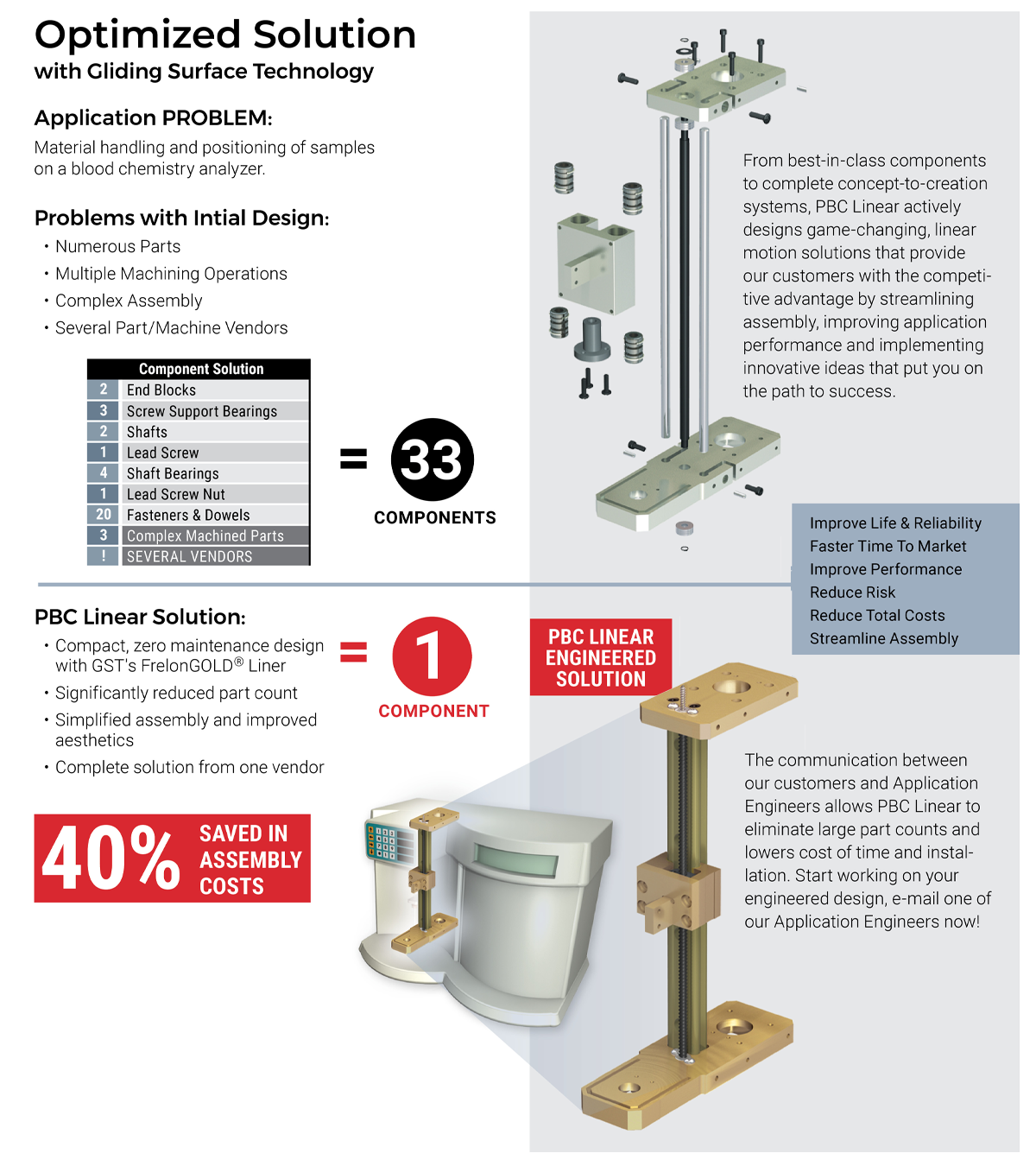
Optimized Solution