CAM Roller Technology
Product Comparison
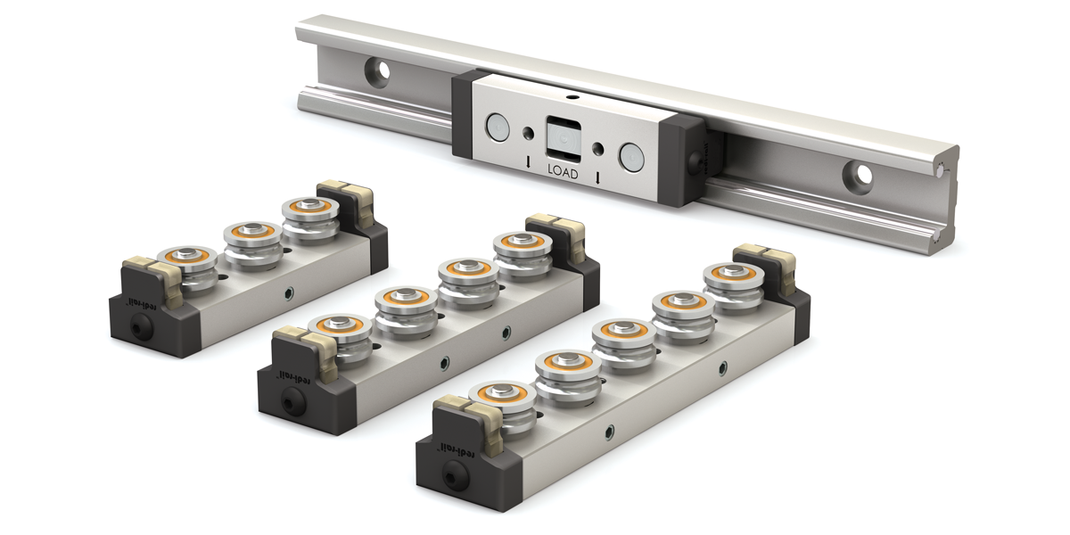
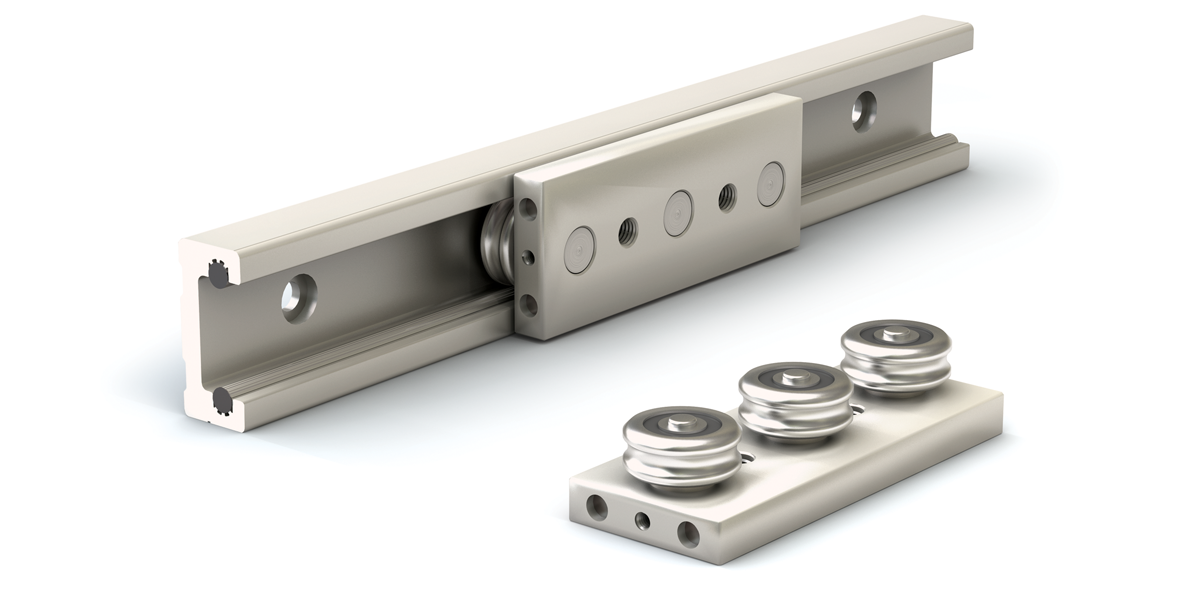
Redi-Rail
Metric Series
Radial capacities from 1,000 N–5,950 N
Patented Side adjustable preload makes fine-tuning easy for the optimal fit
Redi-Rail
Inch Series
Radial capacities from 340 lb.–850 lb.
Industrial strength rail and slider are sealed against contamination
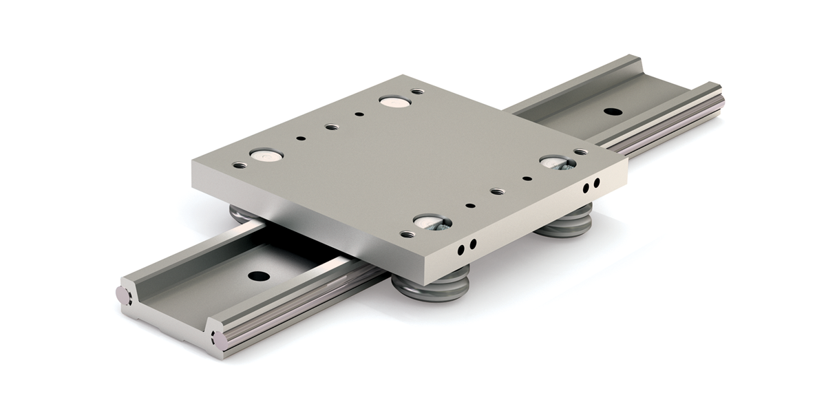
Low Profile Redi-Rail
Radial capacity to 1,220 N
Low 19 mm profile is lightweight and thrives in tight spaces
Hevi-Rail
Bearing and rail system static radial capacities from 5.23 kN–59.2 kN
Heavy duty bearing system handles extremely high loads and is cost effective
Commercial Rail
Radial capacities from 210 N–1,330 N
Roll formed rails and machined aluminum slider body with preload adjustability
Hardened Crown Roller
Loads to 300 lb.
Low cost, strong, long-lasting solution
V-Guide
Radial capacities from 1,260 N–9,991 N
Industry standard v-wheels and rails are a versatile linear motion solution
Applications
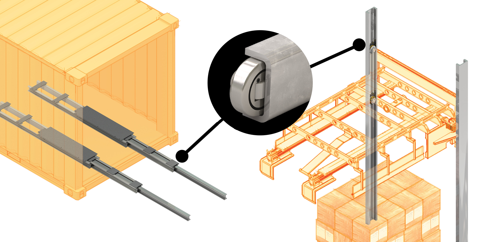
Rack Systems & Mobile Command Centers
Hevi-Rail® combined roller systems handle extremely high loads in industrial strength applications. Systems can be optimized to provide telescopic sliding solutions.
Depalletizers & Heavy duty lift systems
Cam Roller products from PBC Linear, such as Hevi-Rail, provide the industrial strength and cantilever load capabilities required in heavy duty lift systems.
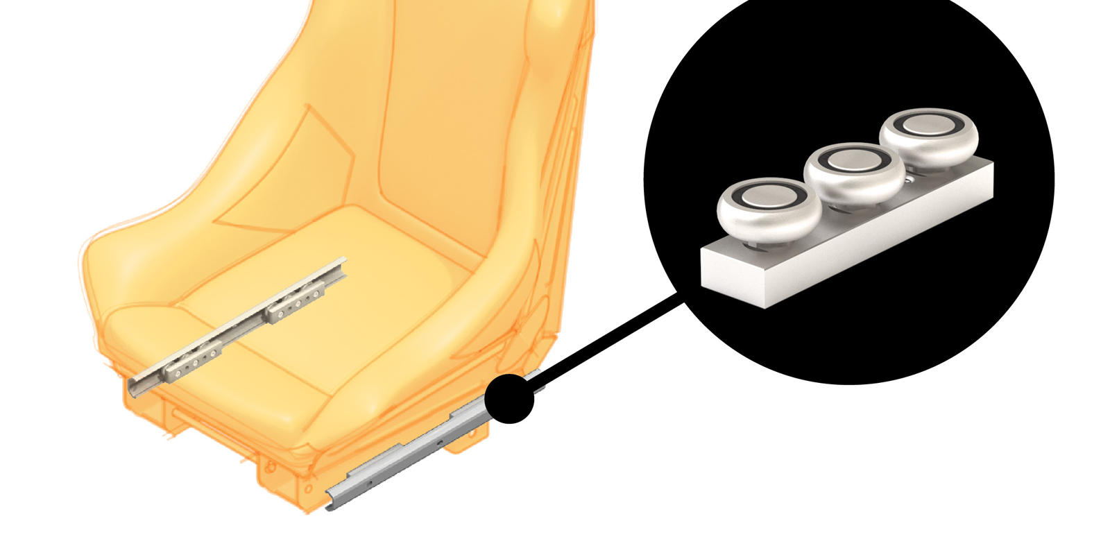
Ergonomic & Mobile Seat Adjustment
Commercial Rail roller bearings, Redi-Rail®, and Hardened Crown Roller each offer reliable mechanical roller systems for seat adjustment in clean and dirty environments.
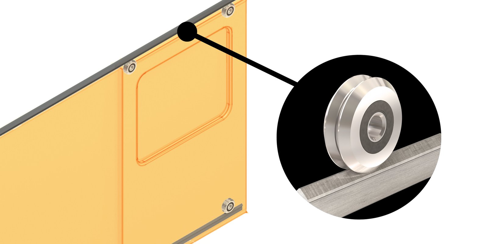
Sliding Doors
V-Guide wheels and rails are ideal for sliding door mechanisms. They provide smooth and quiet travel in a wide range of environments.
Medical & Laboratory Equipment
Redi-Rail provides smooth and consistent rolling performance for medical applications such as tables, carts, and chairs.
Kiosk & Automated Retail
A motion control solution, such as Redi-Rail®, has many benefits including reduced part count, decreased installation costs, and improved performance.

Mobile Equipment
PBC Linear Hevi-Rail® and Commercial Rail provide top quality motion control and thrive in harsh environments: extreme temperatures, heavy vibration, high loads, and contaminants.
Material Handling & Heavy Duty Industrial Systems
Hevi-Rail bearings provide smooth linear guidance in the toughest applications. Hevi-Rail is an economical solution in the harshest industrial environments, handling loads up to 6.6 tons per bearing.

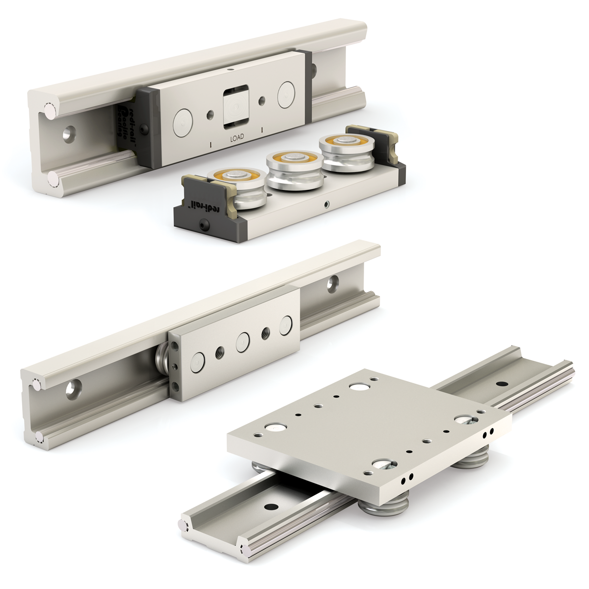
Redi-Rail Linear Guides
Metric Series
Product Overview
- Patented side adjustment feature makes setting preload easy
- Integral seals to wipe raceway
- Gothic arch rollers
- Operating temperature range from -20°C to 80°C (-4°F to 176°F)
- Oil-filled plastic or UHMW spring loaded wipers
- Custom carriages can be designed, engineered, and manufactured to meet your specific requirements
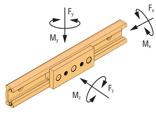
| Series | # of Rollers |
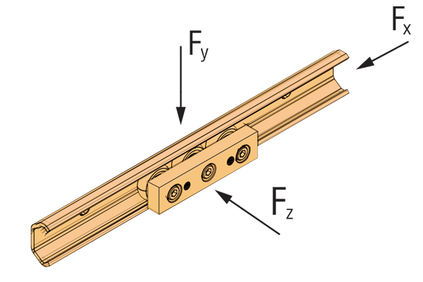
Fd N |
Fy N |
Fz N |
Mx N-M |
My N-M |
Mz N-M |
MAX Speed | |
|---|---|---|---|---|---|---|---|---|---|
| M/min | M/S | ||||||||
| RR14 | 3 | 1,440 | 1,000 | 330 | 2 | 6 | 13 | 300 | 5 |
| RR30 | 4 | 1,440 | 1,000 | 440 | 4 | 11 | 25 | 300 | 5 |
| RR30 | 5 | 2,160 | 1,500 | 550 | 4 | 17 | 38 | 300 | 5 |
| RR45 | 3 | 4,404 | 2,660 | 827 | 7 | 20 | 48 | 420 | 7 |
| RR45 | 4 | 4,404 | 2,660 | 1,103 | 13 | 40 | 96 | 420 | 7 |
| RR45 | 5 | 6,606 | 3,990 | 1,379 | 13 | 60 | 144 | 420 | 7 |
| RR65 | 3 | 10,200 | 5,950 | 1,678 | 19 | 58 | 155 | 480 | 8 |
| RR65 | 4 | 10,200 | 5,950 | 2,237 | 38 | 116 | 309 | 480 | 8 |
| RR65 | 5 | 15,300 | 8,925 | 2,796 | 38 | 175 | 464 | 480 | 8 |
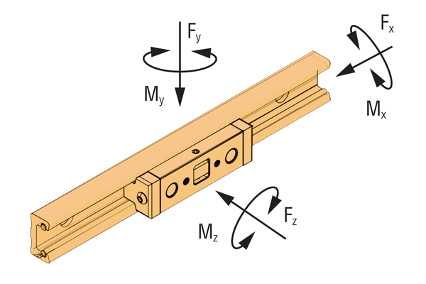
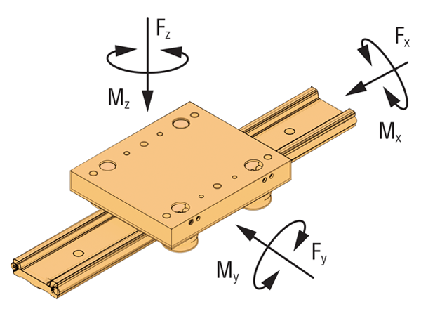
\( F_d \) = Dynamic capacity (LC)
\( F_z \) = Axial capacity
\( F_y \) = Radial capacity
\( M_x, M_y, M_z \) = Moment capacities
Conversions
newton (N) • 0.2248 = lb.
(lb) meter • 0.0397 = inch
newton - meter (N-m) • 8.851 = in.-lb.
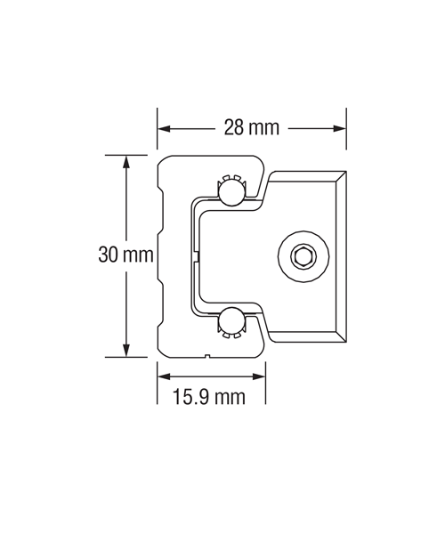
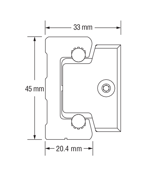
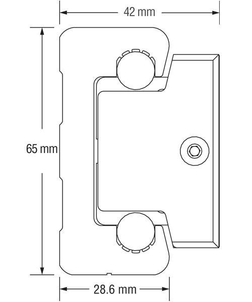
1:1 Scale Dimensions shown in mm
RR30
RR45
RR65
Inch Series
| Series | # of Rollers |
Fd lb. |
Fy lb. |
Fz lb. |
Mx lb./in. |
My lb./in. |
Mz lb./in. |
MAX Speed | |
|---|---|---|---|---|---|---|---|---|---|
| FPM | IPM | ||||||||
| RR14 | 3 | 421 | 340 | 79 | 21 | 54 | 201 | 500 | 6,000 |
| RR18 | 3 | 1,032 | 850 | 168 | 67 | 153 | 677 | 800 | 9,600 |
Low Profile
| Series | # of Rollers |
Fd | Fy | Fz | Mx | My | Mz | MAX Speed | |||||||
|---|---|---|---|---|---|---|---|---|---|---|---|---|---|---|---|
| N | lb. | N | lb. | N | lb. | N-M | lb./in. | N-M | lb./in. | N-M | lb./in. | FPM | IPM | ||
| RRL34 | 4 | 1,488 | 329 | 1,220 | 270 | 510 | 110 | 14 | 120 | 31 | 270 | 13 | 110 | 500 | 6,000 |

\( F_d \) = Dynamic capacity (LC)
\( F_z \) = Axial capacity
\( F_y \) = Radial capacity
\( M_x, M_y, M_z \) = Moment capacities
Conversions
newton (N) • 0.2248 = lb.
(lb) meter • 0.0397 = inch
newton - meter (N-m) • 8.851 = in.-lb.
1:1 Scale Dimensions shown in inches for RR14 & RR18; mm for RRL34
RR14
RR18
RRL34
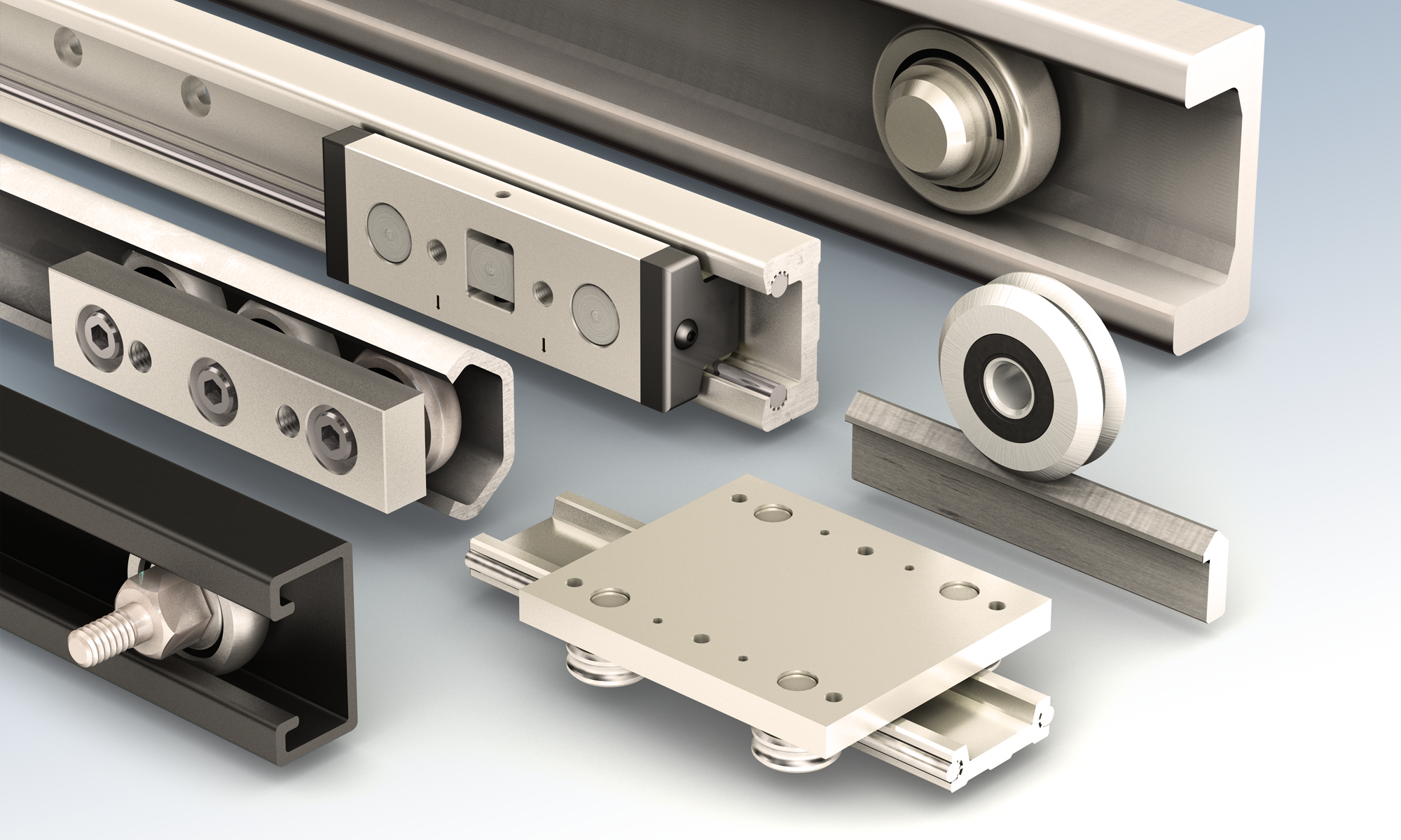
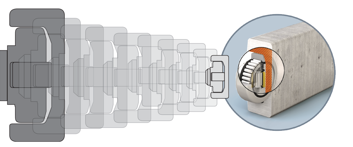
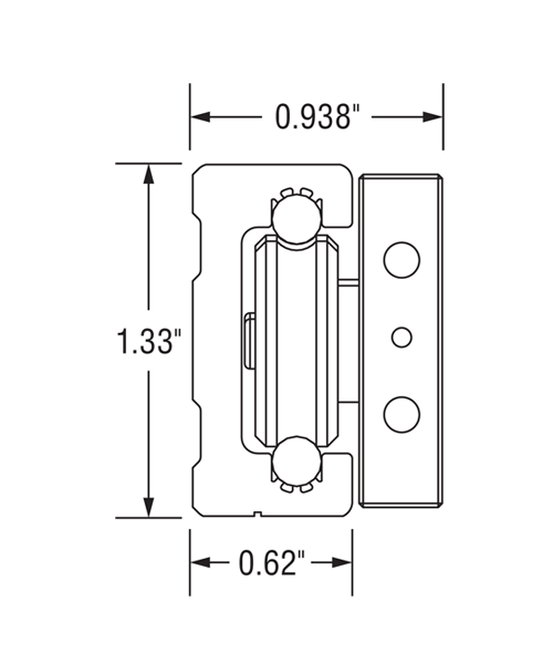
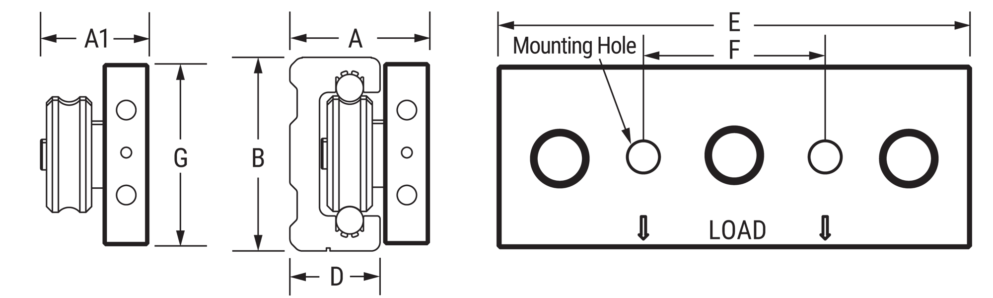
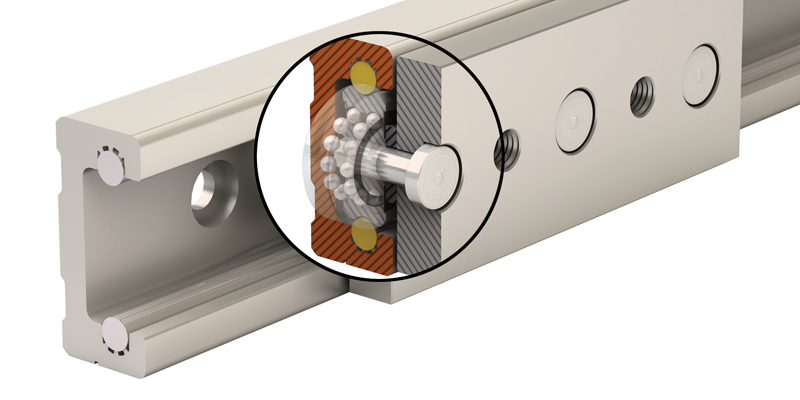
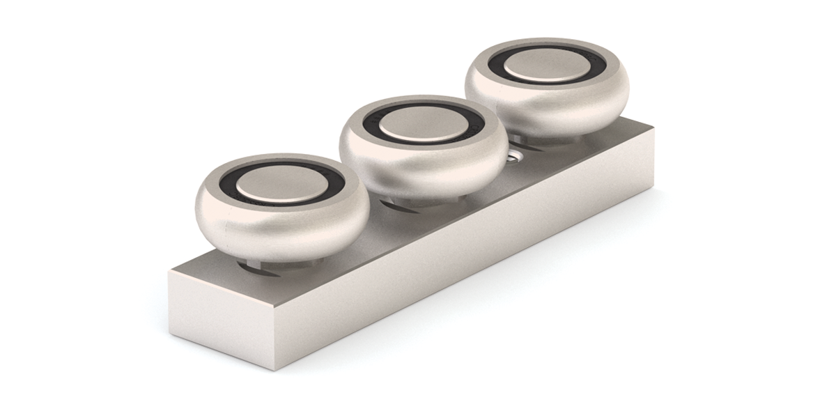
Redi-Rail Linear Guides • ISO Metric Series
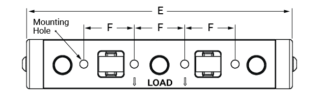
Carriage Dimensions
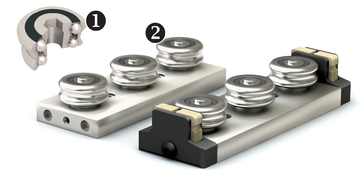
1. Double Row Bearing
High speed & acceleration
2. Sealed Roller
Ideal around contaminants
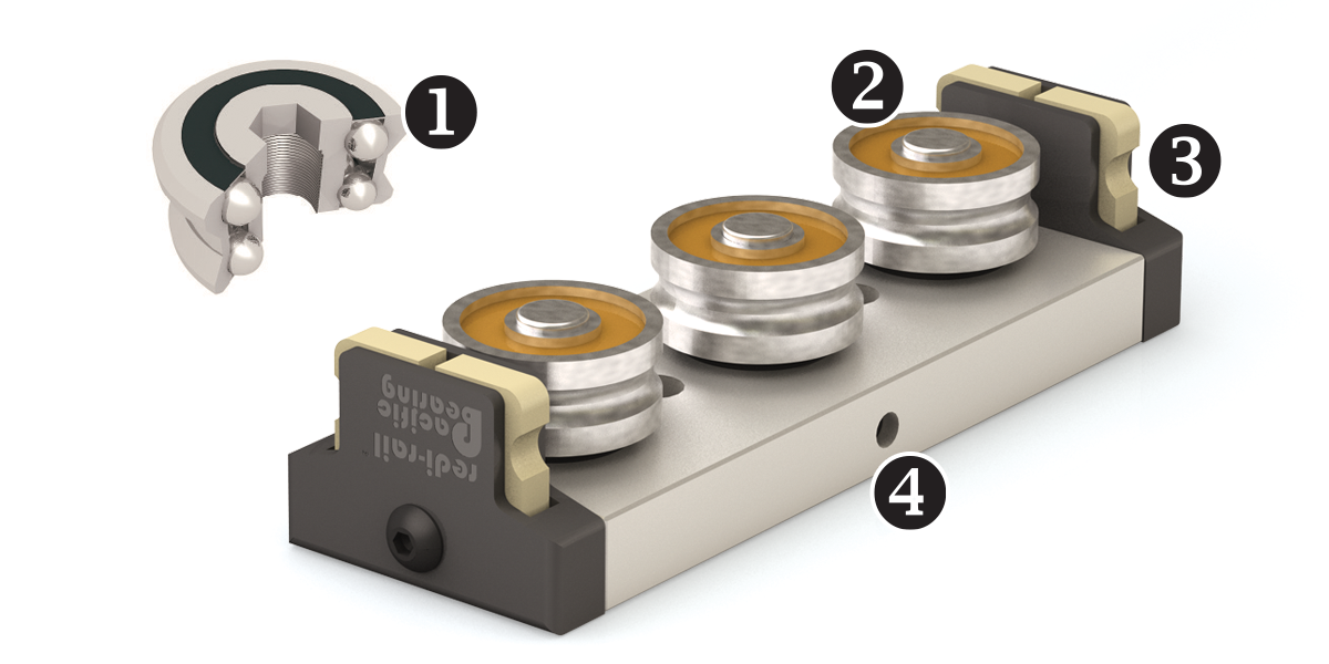
3. Wiper
Molded plastic casing spring-load for even pressure
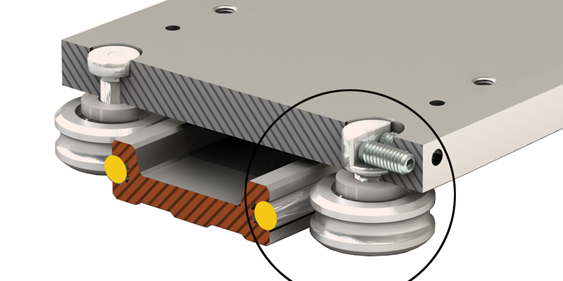
4. Pre-Load Adjustment
Patented side adjustable preload
Load Ratings
| Part No. |
# of Rollers |
Fd N |
Fy N |
Fz N |
Mx N-M |
My N-M |
Mz N-M |
|---|---|---|---|---|---|---|---|
| RRS30 | 3 | 1,440 | 1,000 | 330 | 2 | 6 | 13 |
| 4 | 1,440 | 1,000 | 440 | 4 | 11 | 25 | |
| 5 | 2,160 | 1,500 | 550 | 4 | 17 | 38 | |
| RRS45 | 3 | 4,404 | 2,660 | 827 | 7 | 20 | 48 |
| 4 | 4,404 | 2,660 | 1,103 | 13 | 40 | 96 | |
| 5 | 6,606 | 3,990 | 1,379 | 13 | 60 | 144 | |
| RRS65 | 3 | 10,200 | 5,950 | 1,678 | 19 | 58 | 155 |
| 4 | 10,200 | 5,950 | 2,237 | 38 | 116 | 309 | |
| 5 | 15,300 | 8,925 | 2,796 | 38 | 175 | 464 |
\( F_d \) = Dynamic capacity (LC)
\( F_z \) = Axial capacity
\( F_y \) = Radial capacity
\( M_x, M_y, M_z \) = Moment capacities
Conversions
newton (N) • 0.2248 = lb.
(lb) meter • 0.0397 = inch
newton - meter (N-m) • 8.851 = in.-lb.
Dimensional Information mm
| Part No. |
# of Rollers |
A1 | A | G | B | D | E | F | Mounting Holes |
Weight kg |
|---|---|---|---|---|---|---|---|---|---|---|
| RRS30 | 3 | 22.6 | 28 | 25.4 | 30 | 15.9 | 86.90 | 26 | M5 x 0.8 | 0.09 |
| 4 | 22.6 | 28 | 25.4 | 30 | 15.9 | 112.00 | 26 | M5 x 0.8 | 0.12 | |
| 5 | 22.6 | 28 | 25.4 | 30 | 15.9 | 137.00 | 26 | M5 x 0.8 | 0.17 | |
| RRS45 | 3 | 25.8 | 33 | 38.1 | 45 | 20.4 | 117.00 | 36 | M8 x 1.25 | 0.23 |
| 4 | 25.8 | 33 | 38.1 | 45 | 20.4 | 152.00 | 35 | M8 x 1.25 | 0.28 | |
| 5 | 25.8 | 33 | 38.1 | 45 | 20.4 | 189.50 | 35 | M8 x 1.25 | 0.33 | |
| RRS65 | 3 | 32.3 | 42 | 50.8 | 65 | 28.6 | 162.00 | 52 | M8 x 1.25 | 0.39 |
| 4 | 32.3 | 42 | 50.8 | 65 | 28.6 | 215.35 | 52 | M8 x 1.25 | 0.51 | |
| 5 | 32.3 | 42 | 50.8 | 65 | 28.6 | 268.70 | 52 | M8 x 1.25 | 0.63 |
Carriage Ordering Information
| Redi-Rail Slide | Nominal Size | Wiper Options | Adjustable Pre-Load | Number of Rollers | Corrosion Resistance | ||
| RRS | XX | U | A | - | X | - | SS |
Redi-Rail SlideNominal SizeDimension
Wiper OptionsNo Entry = Oil filled plastic (standard) U = UHMW wipers Adjustable Pre-LoadNumber of Rollers3 = 3 Rollers 4 = 4 Rollers* 5 = 5 Rollers* * 4 and 5 wheel carriages not available in stainless steel option. Corrosion ResistanceSS = 440 SST Rollers Applies only to Stainless Steel Roller Version |
Online Configurator
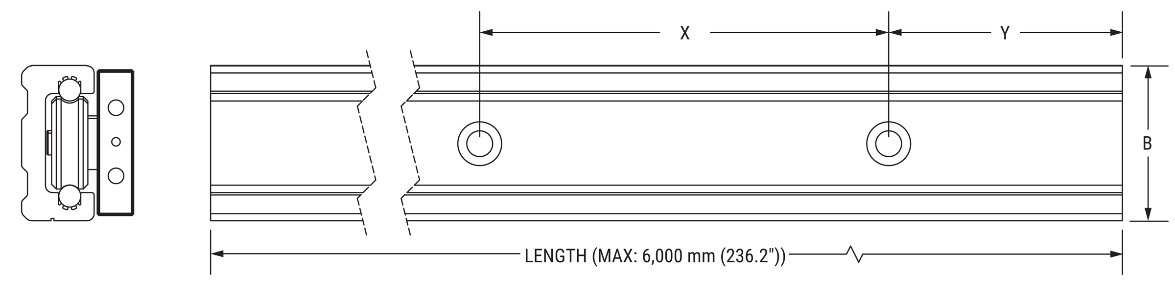
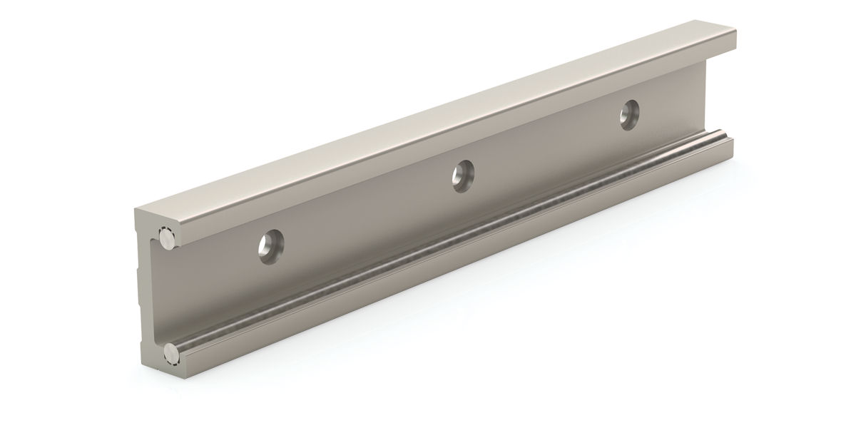
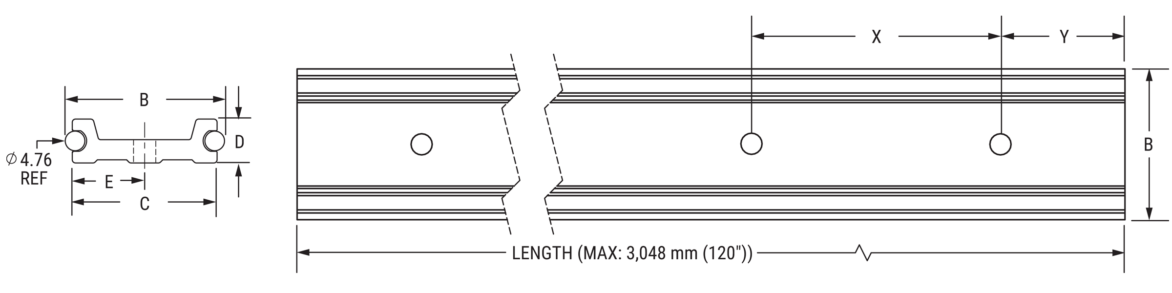
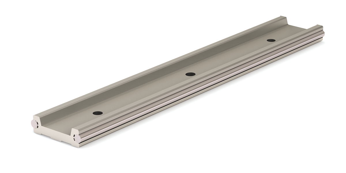
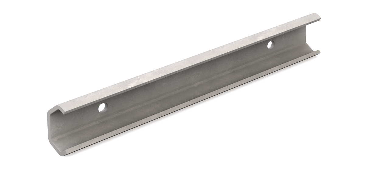
Rail Dimensions
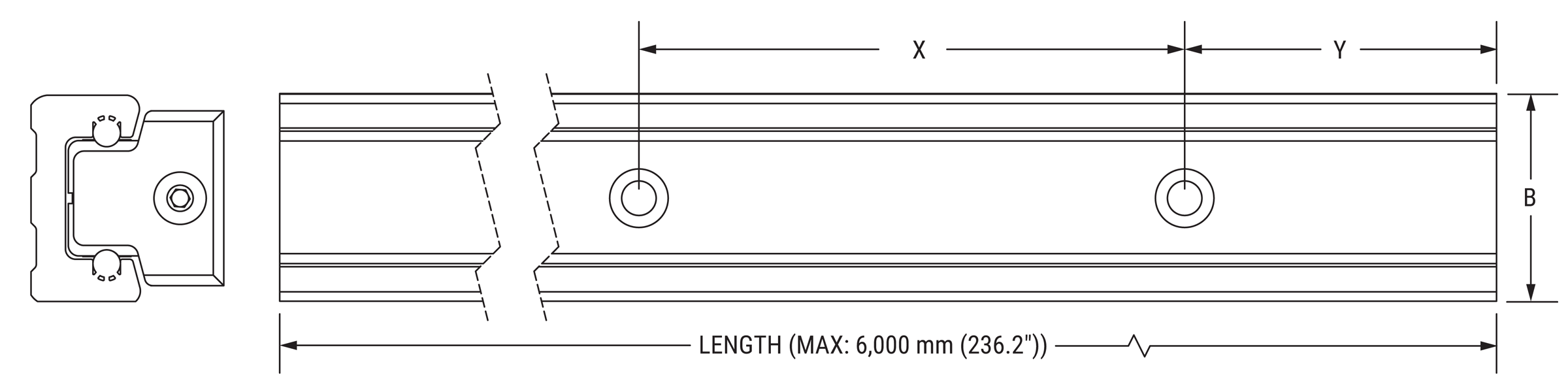
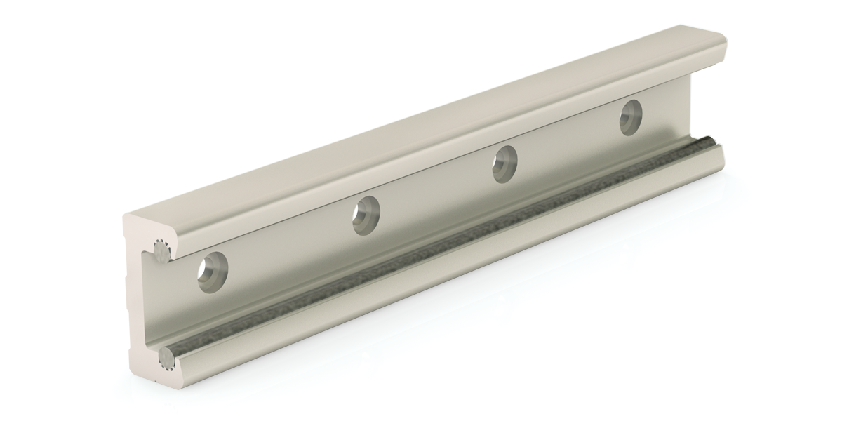
- Aluminum alloy body
- Hardened steel raceway inserts standard or stainless steel inserts optional
Dimensional Information mm
| Part No. |
X | B | Mounting Fasteners |
Weight kg/m |
|---|---|---|---|---|
| RR30 | 60 | 30 | M5 BHCS | 0.868 |
| RR45 | 60 | 45 | M6 BHCS | 1.718 |
| RR65 | 80 | 65 | M6 BHCS | 3.758 |
Note: Rail lengths are available up to 6 m. Y dimension is specified by customer at time of order. If Y is not specified, holes are centered on length of rail. BHCS - Button Head Cap Screw.
Roller/Shaft Interface
- Gothic Arch Contact for smooth, high speed performance

Rail Ordering Information
| Redi-Rail | Nominal Size | Rail Type | Length | |
| RR | XX | - | XXXX | |
Redi-RailNominal SizeDimension
Rail TypeBlank = Rail with steel rods (standard) CR = Corrosion resistant rail with 440 SST rods Length (mm)Example: 1200 mm, MAX: 6,000 mm (236.2") |
Online Configurator
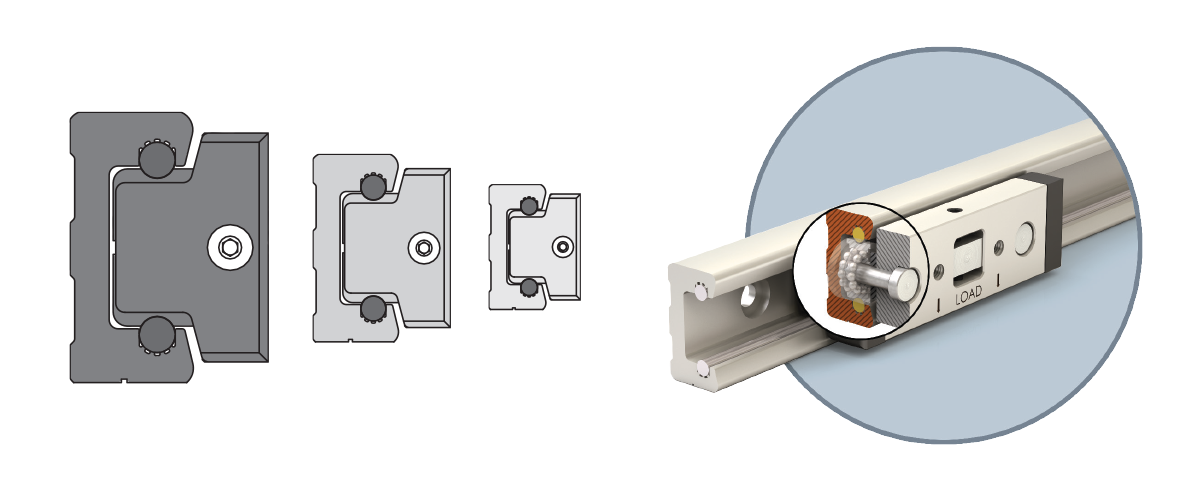
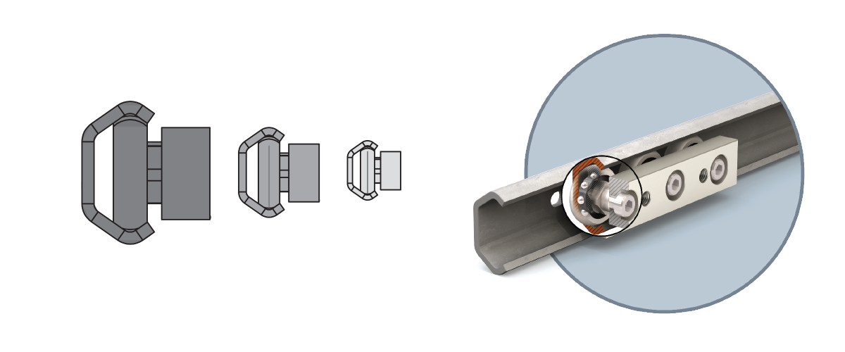
Redi-Rail Linear Guides • Inch Series
Carriage Dimensions
1. Double Row Bearing
High speed & acceleration
2. Sealed Roller
Ideal around contaminants
Load Ratings
| Part No. |
Fd lb. |
Fy lb. |
Fz lb. |
Mx lb.-in. |
My lb.-in. |
Mz lb.-in. |
|---|---|---|---|---|---|---|
| RRS14/PW | 421 | 340 | 79 | 21 | 54 | 201 |
| RRS18/PW | 1,032 | 850 | 168 | 67 | 153 | 677 |

\( F_d \) = Dynamic capacity (LC)
\( F_z \) = Axial capacity
\( F_y \) = Radial capacity
\( M_x, M_y, M_z \) = Moment capacities
Conversions
newton (N) • 0.2248 = lb.
(lb) meter • 0.0397 = inch
newton - meter (N-m) • 8.851 = in.-lb.
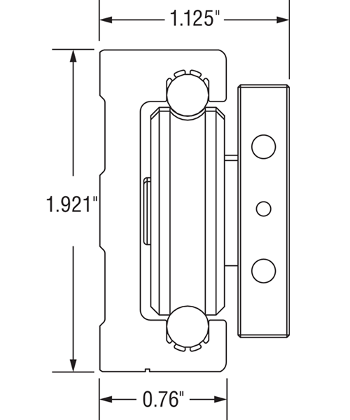
Dimensional Information inches
| Part No. |
A1 | A | G | B | D | E | F | Mounting Holes |
Weight lb. |
|---|---|---|---|---|---|---|---|---|---|
| RRS14 | 0.702 | 0.938 | 1.25 | 1.32 | 0.62 | 3.25 | 1.250 | 1/4-28 | 0.25 |
| RRS14PW | 4.13 | ||||||||
| RRS18 | 0.823 | 1.125 | 1.50 | 1.91 | 0.76 | 4.50 | 1.625 | 5/16-24 | 0.50 |
| RRS18PW | 5.36 |
Carriage Ordering Information
| Redi-Rail Slide | Nominal Size | Wiper Option | Fixed Pre-Load | Number of Rollers | Corrosion Resistance | ||
| RRS | XX | PW | F | - | 3R | - | SS |
Redi-Rail SlideNominal SizeDimension
Wiper OptionsNo Entry = No wipers PW = Oil filled plastic wipers Fixed Pre-LoadApplies only to Stainless Steel Roller Version Number of RollersApplies only to Stainless Steel Roller Version Corrosion ResistanceSS = 440 SST Rollers Applies only to Stainless Steel Roller Version |
Online Configurator
Rail Dimensions
- Aluminum alloy body
- Hardened steel raceway inserts standard or stainless steel inserts optional
Dimensional Information inches
| Part No. |
X | B | Mounting Fasteners |
Weight lb./ft |
|---|---|---|---|---|
| RR14 | 3.5 | 1.32 | #10 BHCS | 0.56 |
| RR18 | 3.5 | 1.91 | 1/4" BHCS | 0.85 |
Note: Rail lengths are available up to 19' (6 m). Y dimension is specified by customer at time of order. If Y is not specified, holes are centered on length of rail. BHCS - Button Head Cap Screw
Roller/Shaft Interface
- Gothic Arch Contact for smooth, high speed performance
Rail Ordering Information
| Redi-Rail | Nominal Size | Rail Type | Length | |
| RR | XX | - | XXX.XXX | |
Redi-RailNominal SizeDimension
Rail TypeBlank = Rail with steel rods (standard) CR = Corrosion resistant rail with 440 SST rods Length (inches)Example: 072.000", MAX: 6000 mm (236.2") |
Online Configurator
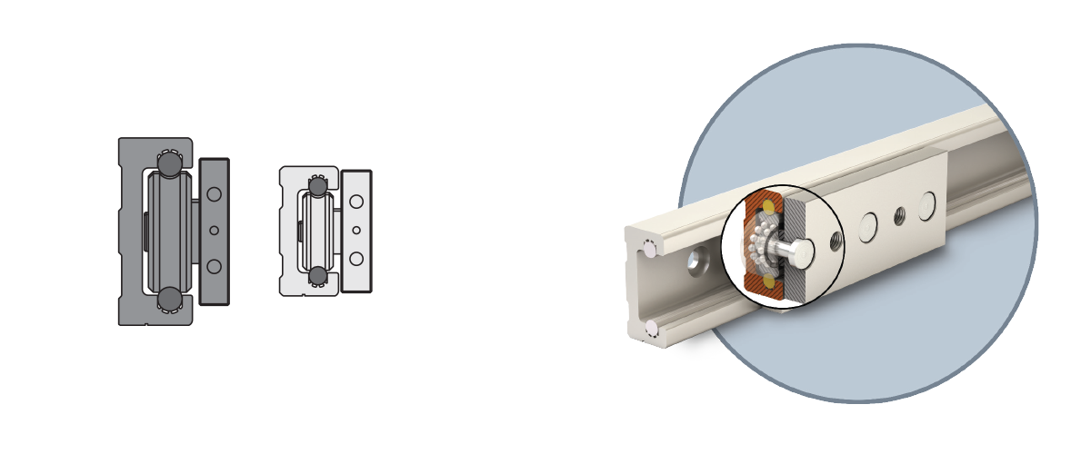
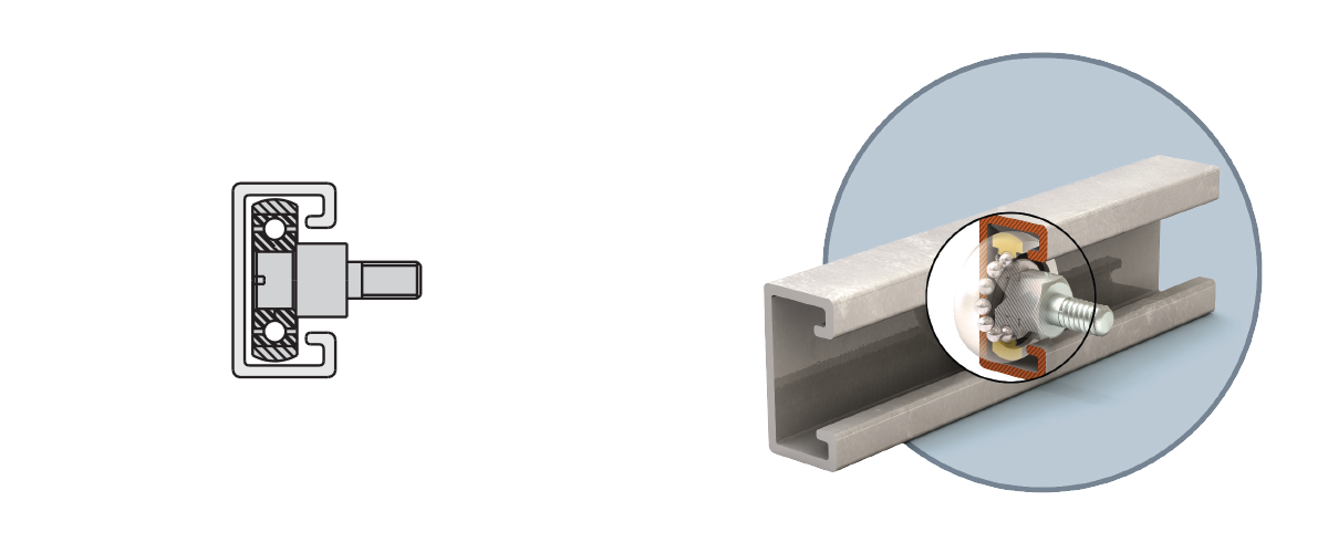
Redi-Rail Linear Guides • Low Profile
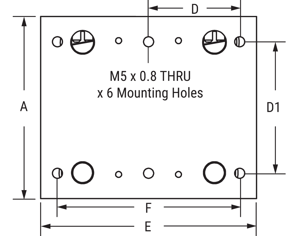
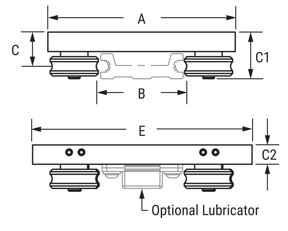
Carriage Dimensions
1. Double Row Bearing
High speed & acceleration
2. Sealed Roller
Ideal around contaminants
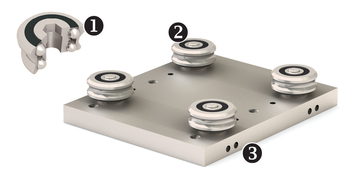
3. Pre-Load Adjustment
Patented side adjustable preload
Load Ratings
| Part No. |
Fy | Fz | Mx | My | Mz | |||||
|---|---|---|---|---|---|---|---|---|---|---|
| n | lb. | n | lb. | n-m | lb./in. | n-m | lb./in. | n-m | lb./in. | |
| RRL34C | 1,220 | 270 | 510 | 110 | 14 | 120 | 31 | 270 | 13 | 110 |
\( F_d \) = Dynamic capacity (LC)
\( F_z \) = Axial capacity
\( F_y \) = Radial capacity
\( M_x, M_y, M_z \) = Moment capacities
Conversions
newton (N) • 0.2248 = lb.
(lb) meter • 0.0397 = inch
newton - meter (N-m) • 8.851 = in.-lb.
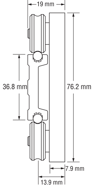
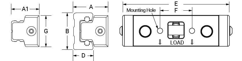
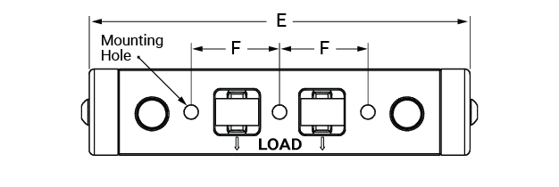
Dimensional Information mm
| Part No. |
A | B | C | C1 | C2 | D | D1 | E | F | Mounting Holes |
Weight lb. |
|---|---|---|---|---|---|---|---|---|---|---|---|
| RRL34C | 76.2 | 36.8 | 13.9 | 19 | 7.9 | 38 | 55 | 90 | 76 | M5 x 0.8 Thru x 6 |
0.5 |
Carriage Ordering Information
| Low Profile Redi-Rail | Size 34 | Carriage | Carriage Style | Roller Type | Wiper/Lubricator | System Height | Preload | Corrosion Resistance | |||
| RRL | 34 | C | - | A | X | - | X | 19 | A | - | C0 |
Low Profile Redi-RailSize 34CarriageNo Entry = No wipers PW = Oil filled plastic wipers Carriage StyleA = 4-Roller Flat Plate Roller Type2 = Sealed Steel (Std) 3 = Sealed Stainless Steel Wiper/Lubricator0 = Nothing 1 = Lube Pad (wiper) System height19 mm PreloadA = Side Adjustable (Std) Corrosion ResistanceC0 = Clear Anodize (Std) |
Online Configurator
Rail Dimensions
- Aluminum alloy body
- Hardened steel raceway inserts
Dimensional Information mm
| Part No. |
B | C | D | E | X | Mounting Fasteners |
Weight kg/m |
|---|---|---|---|---|---|---|---|
| RRL34 | 36.8 | 33.5 | 10.2 | 16.8 | 80 | M5 BHCS | 0.7559 |
Note: Rail lengths are available up to 10 ft (3048 mm). Y dimension is specified by customer at time of order. If Y is not specified, holes are centered on length of rail. BHCS - Button Head Cap Screw.
Roller/Shaft Interface
- Gothic Arch Contact for smooth, high speed performance
Rail Ordering Information
| Low Profile Redi-Rail | Size 34 | Rail | Length | Corrosion Resistance | ||
| RRL | 34 | R | - | XXX.XXX | - | RX |
Low Profile Redi-RailSize 34Dimension
RailBlank = Rail with steel rods (standard) CR = Corrosion resistant rail with 440 SST rods Length (inches)MAX: 120 inches (3,048 mm) Corrosion ResistanceR0 = Clear anodize aluminum rail with RC60 steel shafting (Standard) R1 = Clear anodize aluminum rail with stainless shafting |
Online Configurator
Redi-Rail Linear Guides Overview
Product Overview
- Sealed double row bearings provide smooth linear guidance that is maintenance free
- Side adjusted preload simplifies assembly and installation
- Operating temperature range from -20°C to 80°C (-4°F to 176°F)
- Butt-joinable for longer lengths
- Available in Inch or ISO Metric
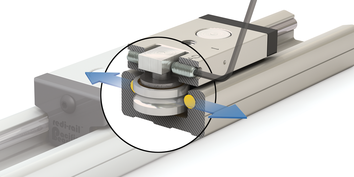
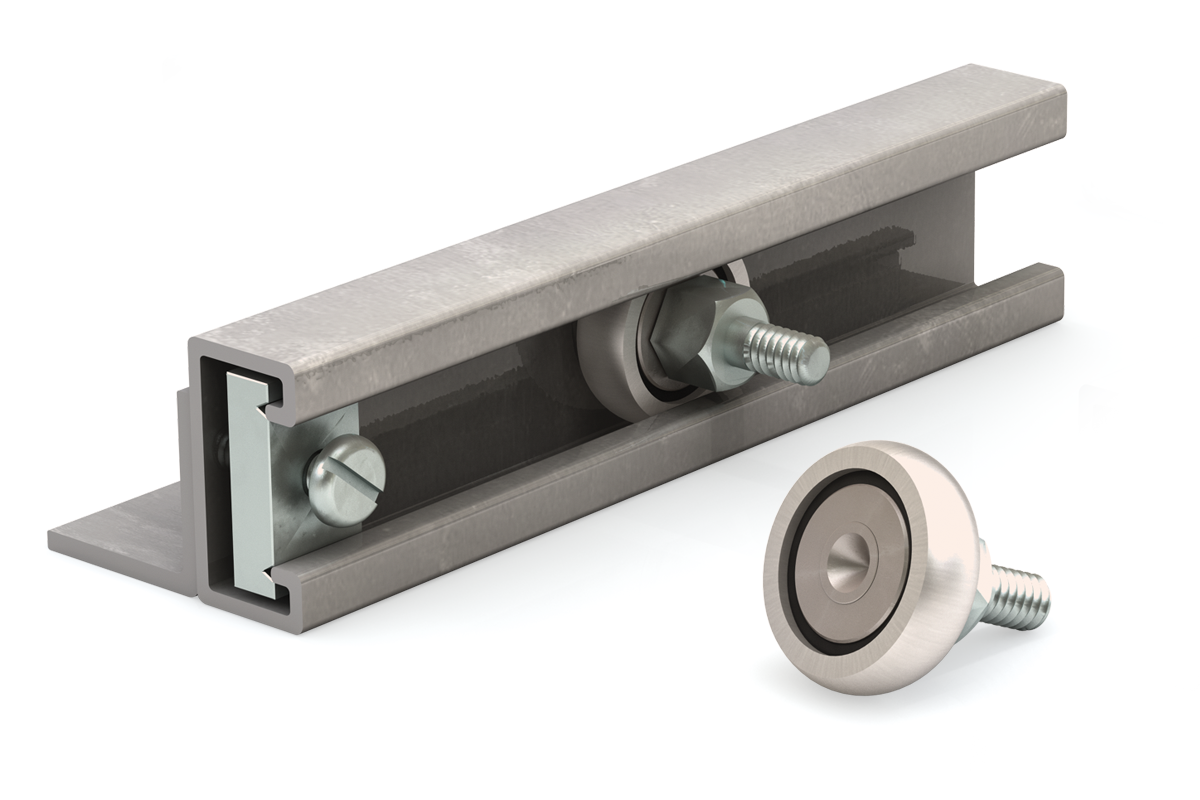
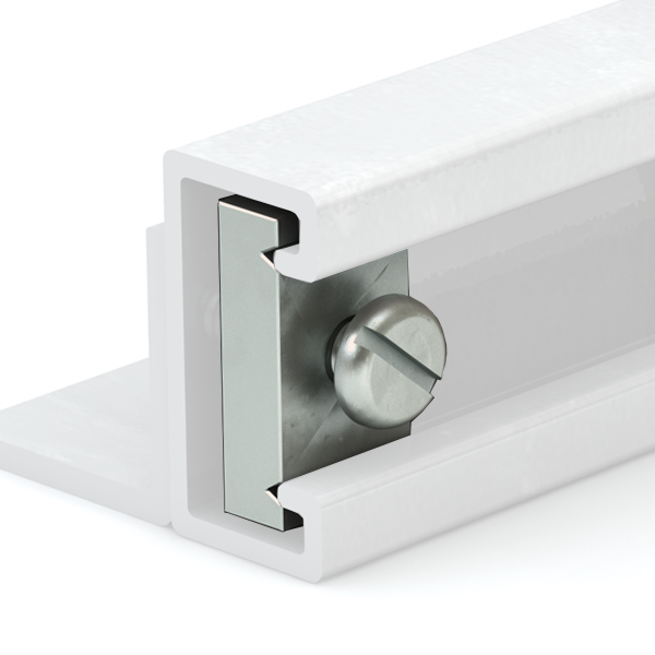
Adjusting Slide Preload ON Metric Series
Slide preload is initially set by the factory. If further adjustments are needed, here are some simple steps to follow:
- To loosen the eccentric (center) roller, use an allen wrench to loosen the screw that is on the side of the mounting block. Be sure to loosen the screw that is on the side of the
direction you want the roller to move. - When it is loose, tighten the set screw on the opposite side of the block. This will move the roller and mounting stud.
- Make a very small change, retighten the first set screw, and try it out. If the preload is too loose, you will feel the slider rock and you will hear a slight “clunk.” If it is too tight, the slider will roll rough, like riding a bicycle on a gravel road.
- Move the slide along the length of the rail by hand. Adjust it so that it does not feel loose anywhere. It may take you several times to get the proper adjustment.
- Make sure the rollers are tightened with the proper adjustment prior to operation. It is recommended to loc the set screws in place with a breakable threadlocker so they will hold position and minimize any effects of vibration.
Mounting Slider body & Max Capacity
The table shows recommended bolt tightening torques for mounting to the slide body. Be sure to use bolts that are long enough to obtain full thread engagement.
Lubrication - Rails & Bearings
Redi-Rail rollers are internally lubricated for life, but the rails must always have a layer of grease. As a guideline, reapply fresh grease every 50,000 cycles. PBC Linear recommends white lithium based grease.
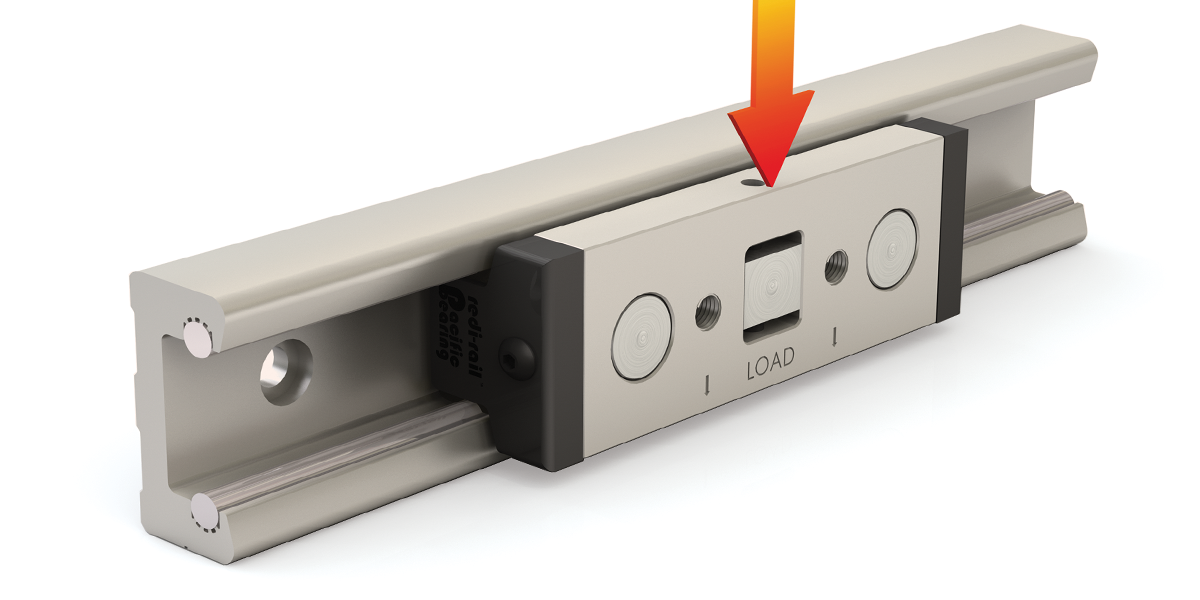
Slider Orientation
The 3-roller slide should be installed in the rail so the load is shared on the two outside rollers. The orientation marks indicate how to align the slider with the load direction.
MOUNTING TORQUE
| Part No. | in.-lb. Torque | Nm Torque |
|---|---|---|
| RRS14, RRS30 | 25 | 3 |
| RRS18, RRS45 | 70 | 8 |
| RRS65 | 150 | 24 |
Life Calculations
\( F_d \) = Dynamic capacity (LC)
\( F_z \) = Axial capacity
\( F_y \) = Radial capacity
\( M_x, M_y, M_z \) = Moment capacities
Conversions
newton (N) • 0.2248 = lb.
(lb) meter • 0.0397 = inch
newton - meter (N-m) • 8.851 = in.-lb.
| Part No. Inch |
Fy lb. |
Fz lb. |
Mx lb.-in. |
My lb.-in. |
Mz lb.-in. |
|---|---|---|---|---|---|
| RRS14 | 336 | 79 | 21.0 | 54.0 | 201.0 |
| RRS18 | 847 | 168 | 67.0 | 153.0 | 677.0 |
| Metric | N | N | Nm | Nm | Nm |
| RRS30 | 1,002 | 330 | 1.8 | 5.5 | 12.5 |
| RRS45 | 2,660 | 827 | 6.6 | 19.9 | 47.9 |
| RRS65 | 5,950 | 1,678 | 19.0 | 58.2 | 154.7 |
To calculate an approximate life for Redi-Rail sliders, use the following equation:
Inch Series
\( L_{RR} = 10^7 \cdot \left( \frac{F_d}{\text{Load}_{\text{Equiv}} \cdot RF} \right)^{3.0} \, \text{(inches)} \)
\( F_d \) = Slider Life Capacity which is found in the table
\( \text{Load}_{\text{Equiv}} \) = Equivalent Radial Load found from the following equation:
\( \text{Load}_{\text{Equiv}} = F_y \cdot \left( \frac{\text{Load}_{\text{Axial}}}{F_z} + \frac{M_x}{M_{x, \text{MAX}}} + \frac{M_y}{M_{y, \text{MAX}}} + \frac{M_z}{M_{z, \text{MAX}}} \right) + \text{Load}_{\text{Radial}} \)
| Part No. | Speedfpm | Speedipm | Fd |
|---|---|---|---|
| RRS14 | 500 | 6,000 | 421 |
| RRS18 | 800 | 9,600 | 1,032 |
Metric Series
\( L_{RR} = \left( \frac{F_d}{\text{Load}_{\text{Equiv}} \cdot RF} \right)^{3.0} \cdot 100,000 \, \text{(meters)} \)
\( F_d \) = Slider Life Capacity which is found in the table
\( \text{Load}_{\text{Equiv}} \) = Equivalent Radial Load found from the following equation:
\( \text{Load}_{\text{Equiv}} = F_y \cdot \left( \frac{\text{Load}_{\text{Axial}}}{F_z} + \frac{M_x}{M_{x, \text{MAX}}} + \frac{M_y}{M_{y, \text{MAX}}} + \frac{M_z}{M_{z, \text{MAX}}} \right) + \text{Load}_{\text{Radial}} \)
| Part No. | Speedm/min | Speedm/s | Fd (N) |
|---|---|---|---|
| RR30 | 300 | 5.0 | 1,440 |
| RR45 | 420 | 7.0 | 4,404 |
| RR65 | 480 | 8.0 | 10,200 |
Note: Reduction factors apply to both inch and metric series
RF = Reduction Factor of the application or environment
= 1.0 to 1.5 for very clean, low speed (<30% MAX), low shocks
= 1.5 to 2.0 or some dirt, moderate speed (30% MAX to 75% MAX),
medium shocks and vibration
= 2.0 to 3.0 for heavy dirt and dust, high speeds (>75% MAX)
and heavy shocks and vibration
Load Comparison


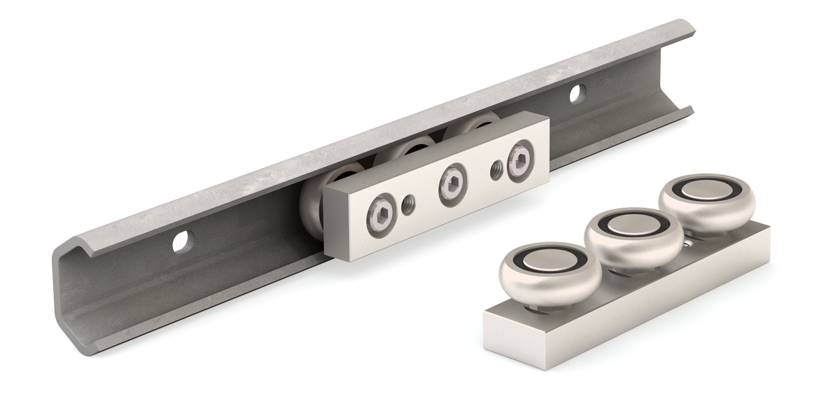
Commercial Rail Linear Guides
Features & Benefits
Commercial Rail is a simple and cost effective linear motion solution with high load capacity and corrosion resistance.
- Precision formed rails available in zinc plated carbon steel
- Speeds up to 1.5 m/s (59 in./s)
- Withstands temperatures up to 100°C (212°F)
- Load capability up to 1,330 N (298 lb.)
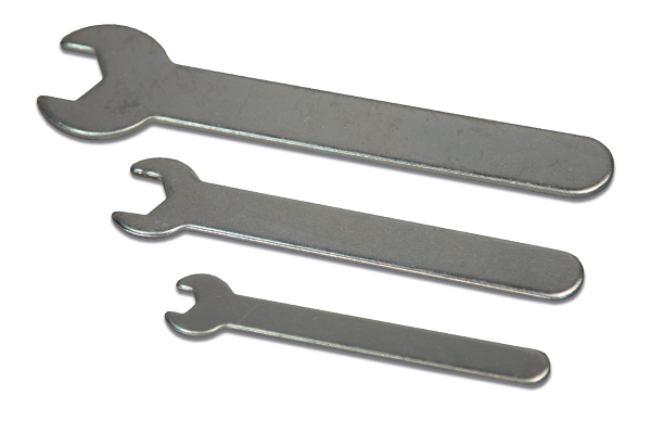
- Open-end wrench available for preload adjustment
| Slider | No. of Rollers |
Fd N |
Fy N |
Fz N |
|
|---|---|---|---|---|---|
| Steel | CR20 | 3 | 280 | 210 | 160 |
| CR30 | 3 | 800 | 610 | 420 | |
| CR45 | 3 | 1,740 | 1,330 | 930 | |
\( F_d \) = Dynamic capacity (LC)
\( F_z \) = Axial capacity
\( F_y \) = Radial capacity
Conversions
newton (N) • 0.2248 = lb.
(lb) meter • 0.0397 = inch
newton - meter (N-m) • 8.851 = in.-lb.
1. Roll Formed Rail
Is corrosion resistant
2. Sealed Roller
Ideal around contaminants
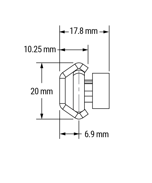
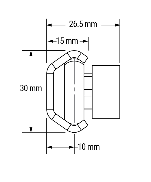
1:1 Scale Dimensions shown in mm
CR20
CR30
CR45
Product Overview
- Roll formed rails made of steel sheet for low cost and corrosion resistance application
- Zinc plated rail length up to 6,000 mm
- Machined slider body made of aluminum alloy and anodized for corrosion resistance
- Steel rollers are made of 52100 chrome steel, hardened and ground, lubricated for life, and sealed against contamination
- Rollers made with thread integrated inner ring for ease of assembly and adjustment of preload
- Custom polymer wipers can be designed and manufactured to improve the smoothness of motion and service life
- Maximum operating temperature of 100°C (212°F)
- Consult with factory for special hole spacing
- Speed up to 1.5 m/s
- Moment loads should be carried by two slides or two parallel rollers
Moments of Inertia
| CR Size | Izz | Iyy | ||
|---|---|---|---|---|
| mm4 | in4 | mm4 | in4 | |
| CR20 | 2,699 | 0.006484 | 533.7 | 0.001282 |
| CR30 | 11,354 | 0.027278 | 2,221.8 | 0.005338 |
| CR45 | 59,907 | 0.143930 | 13,183.0 | 0.031673 |
Material & Finish Specifications
| CR Series Rail | |
|---|---|
| Rail | Carbon steel sheet, Zinc plated |
| Slide | Aluminum alloy anodized |
| Rollers | Chrome steel |
| Hardware | Steel zinc plated |
Slide Orientation
The 3-roller slide should be installed in the rail so that the load is shared among the two outside rollers. The orientation marks indicate how to align the slider with the load direction.
Lubrication – Rails & Bearings
The rollers are internally lubricated for life, but the rails must always have a layer of grease. As a guideline, reapply fresh grease every 50,000 cycles.
Preload Adjustment
- To loosen the center roller, use an Allen wrench to untighten the screw while holding the roller still with an open-end wrench
- Turn the center roller to a position to achieve the desired preload
- Move the slide along the length of the rail by hand, and adjust it so that it does not feel loose anywhere
- Tighten the screw while holding the roller flat with an open-end wrench
| Preload Adjustment | CR20/CRSS20 | CR30/CRSS30 | CR45 |
|---|---|---|---|
| Open-End Wrench | 6 mm | 10 mm | 14 mm |
| PBC Linear Part Number | 6101227 | 6101226 | 6101225 |
Mounting
| Slide | CR20/CRSS20 | CR30/CRSS30 | CR45 |
|---|---|---|---|
| Slide mount screws (Socket head cap) |
M5 | M6 | M8 |
| Tightening torque (in/lb.) | 25 | 43 | 103 |
| Tightening torque (N-m) | 3 | 5 | 12 |
| Rail | |||||
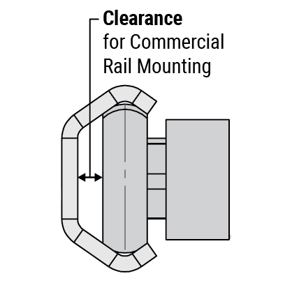
|---|---|---|---|---|---|
| Clearance | Suggested Fastener (Button head cap) |
Head Height* | |||
| Size | Inches | mm | Inches | mm | |
| CR20 | 0.115 | 2.9210 | M4 | 0.087 | 2.20 |
| CR30 | 0.158 | 4.0132 | M5 | 0.108 | 2.75 |
| CR45 | 0.256 | 6.5024 | M8 | 0.433 | 11.00 |
*Head height dimensions meet ISO 7380
Carriage Dimensions
1. Sealed Roller
Ideal around contaminants
2. Machined Body
Anodized aluminum alloy
Load Ratings
| Part No. | Fd N |
Fy N |
Fz N |
|
|---|---|---|---|---|
| Steel | CR20 | 280 | 210 | 160 |
| CR30 | 800 | 610 | 420 | |
| CR45 | 1,740 | 1,330 | 930 | |

\( F_d \) = Dynamic capacity (LC)
\( F_z \) = Axial capacity
\( F_y \) = Radial capacity
Conversions
newton (N) • 0.2248 = lb.
(lb) meter • 0.0397 = inch
newton - meter (N-m) • 8.851 = in.-lb.
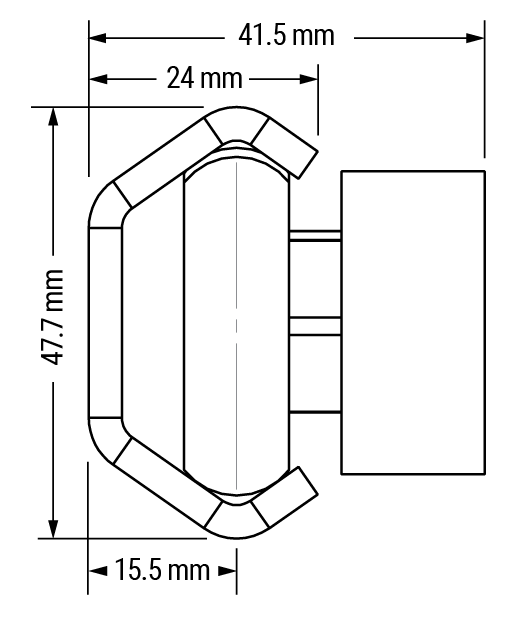
Dimensional Information mm
| Part No. |
A | B | C | D | E | F | G | G1 | J | K | L | M Ø ref |
Y1 | Thread Pitch |
Weight kg |
|---|---|---|---|---|---|---|---|---|---|---|---|---|---|---|---|
| CR20 | 17.8 | 20.0 | 6.9 | 60 | 12.7 | 10.25 | 20 | 20.0 | 12.9 | 6 | 10.9 | 14.0 | 2x Ø 4.2 thru all |
M5 x 0.8 | 0.022 |
| CR30 | 26.5 | 30.0 | 10.0 | 80 | 19.1 | 15.00 | 35 | 22.5 | 20.0 | 10 | 16.5 | 22.8 | 2x Ø 5.0 thru all |
M6 x 1.0 | 0.100 |
| CR45 | 41.5 | 45.7 | 15.5 | 120 | 31.8 | 24.00 | 50 | 35.0 | 31.5 | 15 | 26.0 | 35.5 | 2x Ø 6.8 thru all |
M8 x 1.25 | 0.377 |
Carriage Ordering Information
| Commercial Rail | Rail Size | Type of Body |
| CR | XX | MCA |
Commercial RailRail Size20 = 20 mm 30 = 30 mm 45 = 45 mm Type of BodyMCA = Machined Body |
Online Configurator
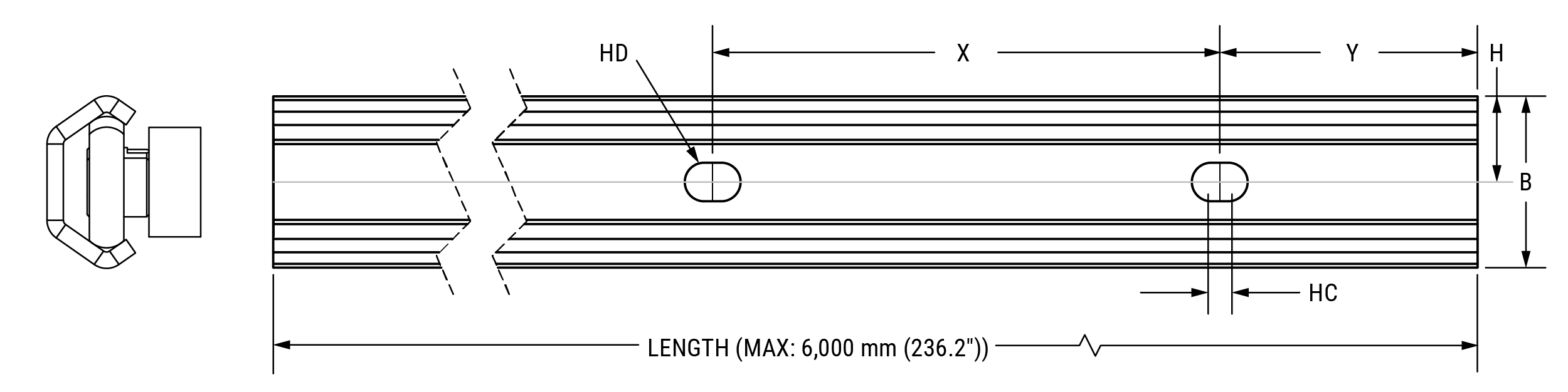
Rail Dimensions
- Precision roll formed rail
- Rail lengths up to 6 m
Dimensional Information mm
| Part No. |
A | B | C | F | H | HC | HD | X | Y | Rail Wt. kg/m |
|---|---|---|---|---|---|---|---|---|---|---|
| CR20 | 17.8 | 20 | 6.9 | 10.25 | 10.0 | 2 | 4.5 | 80 | 40 | 0.46 |
| CR30 | 26.5 | 30 | 10 | 15 | 15.0 | 2 | 5.5 | 80 | 40 | 0.95 |
| CR45 | 41.5 | 45.7 | 15.5 | 24 | 22.9 | 2 | 9.0 | 80 | 40 | 1.95 |
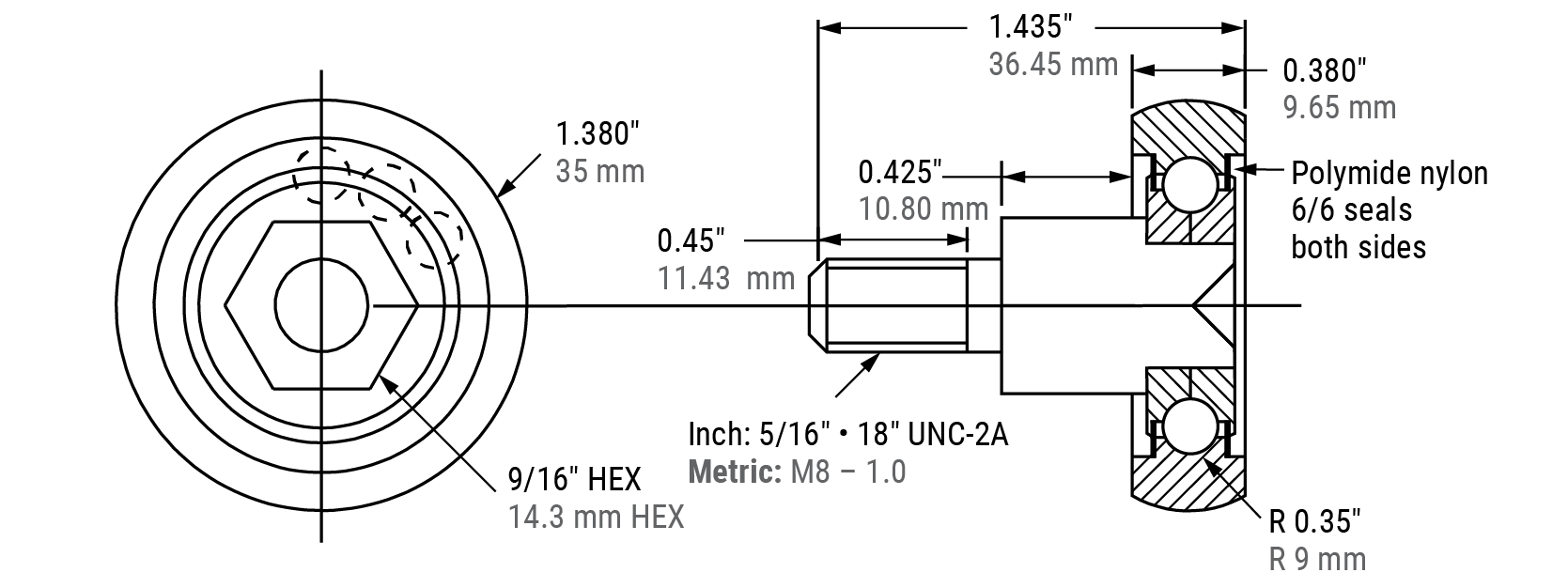
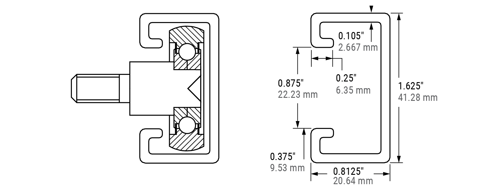
Hardened Crown Rollers
Features & Benefits
Hardened crown rollers are a superb choice for low-cost linear motion. The rollers come pre-assembled and are self-aligning for simple installation. Hardened crown rollers are great for point-to-point applications, and ensure strong, sturdy, and long-lasting linear motion.
- Precision rolling element bearing with polyamide 6/6 seals riding in a Cooper B-Line Series rail
- 9/16" Hex head for easier mounting
- Available with either a 5/16-18 or M8 thread
- Maximum wheel bearing load up to 1,334 N (300 lb.)
- Maximum speed up to 762 mm/s (30 in./s)
- Rails available up to 3 m (10 ft) in steel or powder coated finish
- Contact manufacturer for longer lengths
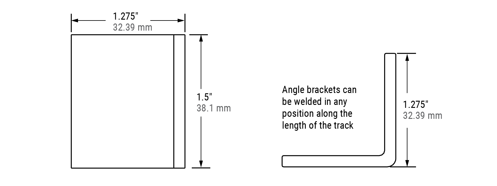
Accessories Available
- Angle brackets (for welding to mounting rail)
- End stops
Cooper B-Line Series
Rail in steel or powder coated finish
Pre-Assembled
Roller
End Stops
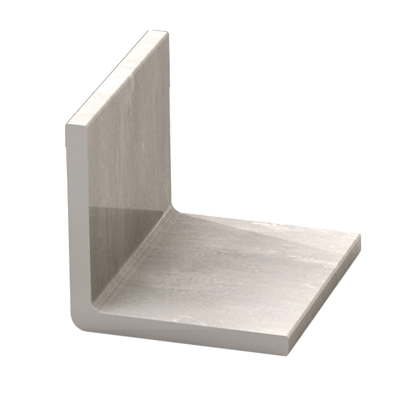
Angle Brackets
For welding to mounting rail
Ordering Information
| Part No. | Description |
|---|---|
| PAC3016 | Hardened Crown Roller Bearing |
| PAC3016M | Hardened Crown Roller Bearing with metric thread |
| PAC2245 | Rail System - unpainted (specify length - priced per foot) |
| PAC2247 | Rail System - black powder coat finish (specify length - price per foot) |
| PAC2244 | Angle Brackets - 1" Steel |
| PAC2246 | End Stops for Rail System (Included: Round head machine screw, ¼"-20 x ¾" Lg, slotted) |
Note: PAC2247 dimensions will vary according to coating thickness.
1:1 Scale
Bearings
Rails
Angle Bracket
End Stop
Note: All metric dimensions are conversions from inch dimensions. All parts are manufactured to inch standards. See ordering information on the previous page.
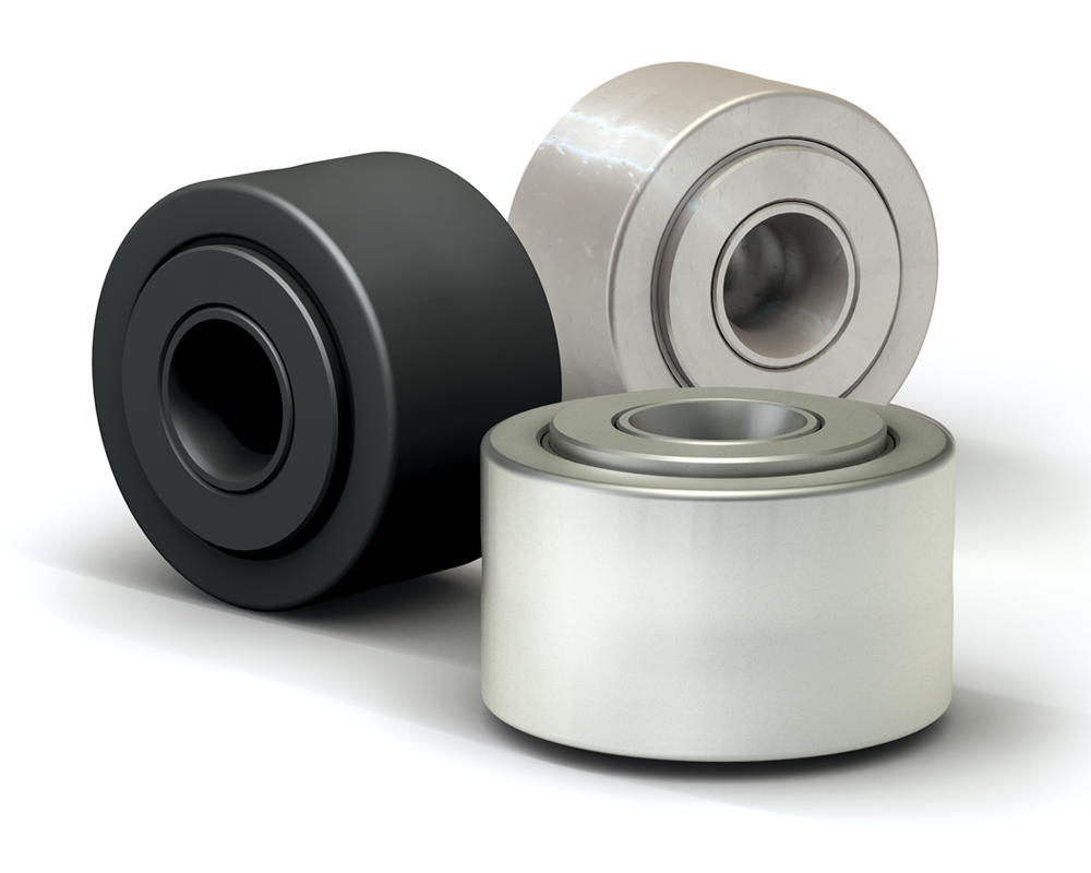
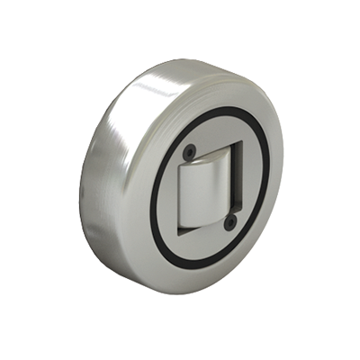
Cam Yoke Rollers
Cam Yoke Rollers are easy to mount and ideal for numerous track roller applications involving moderate loading and shock. Cam Yoke Rollers are composed of high carbon and chromium bearing steel through-hardened and ground outer raceways. Available in chrome plated or stainless steel with a high temp version as an option. These sealed bearings helps to retain lubrication and prevent contamination.
Features/Benefits
- Precision manufacturing to minimize bearing failure which results in costly shutdowns
- Sealed bearings retain lubrication and prevent contamination
- Dimensionally Interchangeable with other standard Cam Yoke Rollers
Lubrication
Cam Yoke Rollers come pre-lubricated. This lubrication is suitable for applications between 5ºF–275ºF (-15ºC–135ºC) and is equipped with corrosion-resistant additives. The rollers can be relubricated via lube holes and lube groove in the inner race bore.
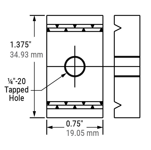
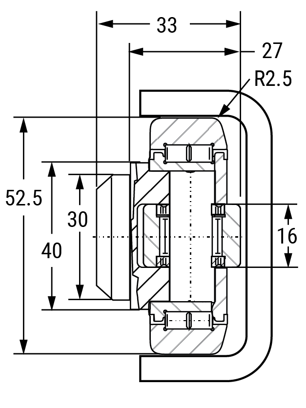
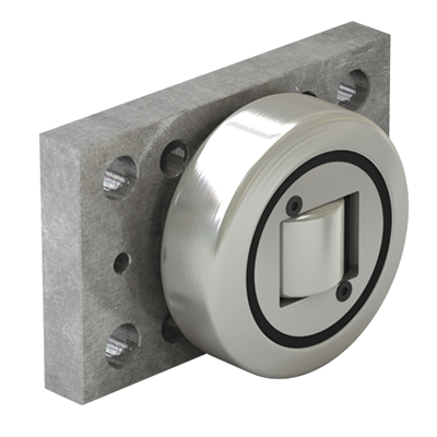
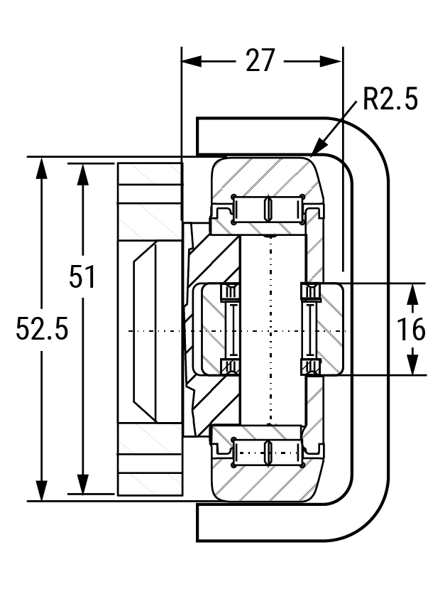
Cam Yoke Roller Installation
To achieve full axial load rating of the Cam Yoke Roller, both sides of the assembly need to be supported. Both end plates should be securely fastened to prevent disassembly. If it is not possible to clamp the bearing endwise, the Cam Yoke Roller can be mounted one-sided with a flat washer added to secure the end plate from disassembly. This method is acceptable but not recommended.
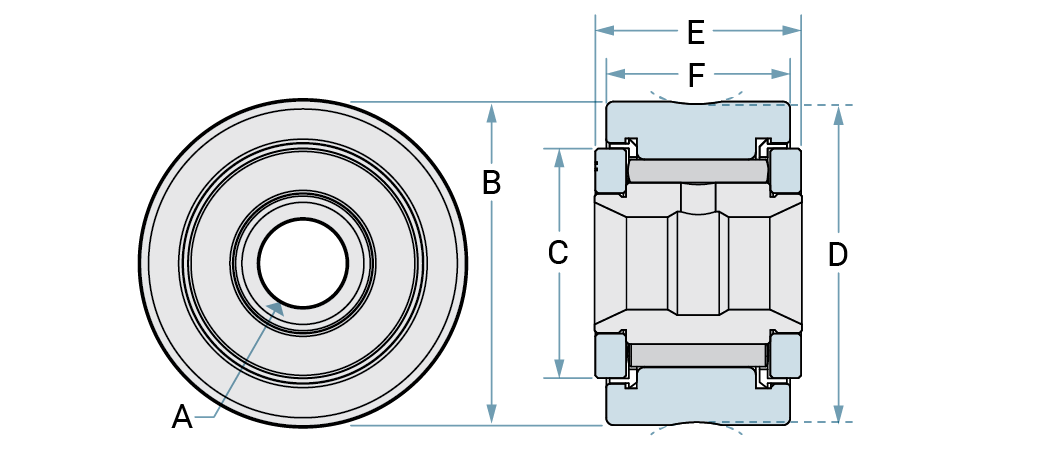
| Part No. | A | B | C | D | E | F | Radial Load X (lb) | Static Load Y (lb) | Weight (g) |
|---|---|---|---|---|---|---|---|---|---|
| 6300060 | 0.1260" | 0.432" | 0.362" | 0.425" | 0.404" | 0.309" | 610 | 725 | 4.54 |
| 6300061 | 1.9750" | 0.558" | 0.470" | 0.553" | 0.469" | 0.430" | 680 | 790 | 11.34 |
| 6300064 | 0.1975" | 0.667" | 0.462" | 0.663" | 0.498" | 0.435" | 995 | 1,215 | 15.88 |
| 6300067 | 0.2499" | 0.850" | 0.625" | 0.845" | 0.560" | 0.498" | 1,660 | 4,130 | 34.02 |
| Part No. | A | B | C | D | E | F | Radial Load X (lb) | Static Load Y (lb) | Weight (g) |
|---|---|---|---|---|---|---|---|---|---|
| 6300069 | 0.3132" | 1.100" | 0.7800" | 1.096" | 0.685" | 0.623" | 2,225 | 6,120 | 65.77 |
| 6300070 | 0.6249" | 2.000" | 1.5625" | 1.938" | 1.310" | 1.248" | 8,090 | 21,140 | 415.04 |
| 6300071 | 0.2500" | 0.875" | 0.6250" | N/A | 0.560" | 0.498" | 1,660 | 4,130 | 34.02 |
| 6300072 | 0.3124" | 1.125" | 0.7813" | N/A | 0.685" | 0.623" | 2,225 | 6,120 | 68.04 |
| 6300073 | 0.4999" | 1.750" | 1.2500" | N/A | 1.060" | 0.998" | 6,385 | 15,840 | 263.08 |
| 6300098 | 0.7500" | 2.500" | 1.4975" | N/A | 1.560" | 1.498" | 11,720 | 32,900 | 814.20 |
| Part No. | A | B | C | D | E | F | Radial Load X (lb) | Static Load Y (lb) | Weight (g) |
|---|---|---|---|---|---|---|---|---|---|
| 6300068 | 0.2499" | 0.875" | 0.6250" | 0.870" | 0.560" | 0.498" | 1,490 | 2,100 | 34.02 |
| Part No. | A | B | C | D | E | F | Radial Load X (lb) | Static Load Y (lb) | Weight (g) |
|---|---|---|---|---|---|---|---|---|---|
| 6300074 | 0.1258" | 0.432" | 0.3620" | 0.429" | 0.406" | 0.310" | 610 | 726 | 4.54 |
| 6300076 | 0.1975" | 0.558" | 0.4700" | 0.553" | 0.469" | 0.431" | 680 | 790 | 11.34 |
| 6300082 | 0.1975" | 0.667" | 0.4975" | 0.663" | 0.498" | 0.435" | 995 | 1,215 | 18.14 |
| 6300087 | 0.2499" | 0.850" | 0.6250" | 0.845" | 0.560" | 0.498" | 1,660 | 4,130 | 31.75 |
| 6300088 | 0.2499" | 0.850" | 0.6250" | 0.870" | 0.560" | 0.498" | 1,660 | 4,130 | 34.02 |
| Part No. | A | B | C | D | E | F | Radial Load X (lb) | Static Load Y (lb) | Weight (g) |
|---|---|---|---|---|---|---|---|---|---|
| 6300090 | 0.3124" | 1.000" | 0.7813" | N/A | 0.685" | 0.623" | 2,225 | 6,120 | 65.77 |
| 6300091 | 0.2499" | 0.875" | 0.6250" | N/A | 0.560" | 0.498" | 1,660 | 4,130 | 34.02 |
| 6300094 | 0.3124" | 1.125" | 0.7813" | N/A | 0.685" | 0.623" | 2,225 | 6,120 | 68.04 |
| Part No. | A | B | C | D | E | F | Radial Load X (lb) | Static Load Y (lb) | Weight (g) |
|---|---|---|---|---|---|---|---|---|---|
| 6300075 | 0.1258" | 0.432" | 0.362" | 0.429" | 0.406" | 0.310" | 610 | 726 | 68.04 |
| 6300077 | 0.1975" | 0.558" | 0.470" | 0.553" | 0.469" | 0.431" | 680 | 790 | 11.34 |
| Part No. | A | B | C | D | E | F | Radial Load X (lb) | Static Load Y (lb) | Weight (g) |
|---|---|---|---|---|---|---|---|---|---|
| 6300118 | 0.3124" | 1.000" | 0.78125" | N/A | 0.685" | 0.623" | 2,225 | 6,120 | 68.04 |
| 6300119 | 0.3124" | 1.125" | 0.78125" | N/A | 0.685" | 0.623" | 2,225 | 6,120 | 65.77 |
| Part No. | A | B | C | D | E | F | Radial Load X (lb) | Static Load Y (lb) | Weight (g) |
|---|---|---|---|---|---|---|---|---|---|
| 6300083 | 0.1975" | 0.667" | 0.472" | 0.663" | 0.498" | 0.435" | 796 | 972 | 15.88 |
| Part No. | A | B | C | D | E | F | Radial Load X (lb) | Static Load Y (lb) | Weight (g) |
|---|---|---|---|---|---|---|---|---|---|
| 6300089 | 0.2499" | 0.875" | 0.625" | 0.870" | 0.560" | 0.498" | 1,490 | 2,100 | 31.75 |
| Part No. | A | B | C | D | E | F | Radial Load X (lb) | Static Load Y (lb) | Weight (g) |
|---|---|---|---|---|---|---|---|---|---|
| 6300092 | 0.2499" | 0.875" | 0.6250" | N/A | 0.560" | 0.498" | 1,490 | 2,100 | 34.02 |
| 6300122 | 0.3124" | 1.000" | 0.78125" | N/A | 0.685" | 0.623" | 2,000 | 5,400 | 22.68 |
| 6300123 | 0.3124" | 1.125" | 0.78125" | N/A | 0.685" | 0.623" | 2,225 | 6,120 | 68.04 |
Online Configurator
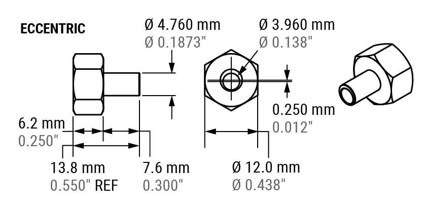
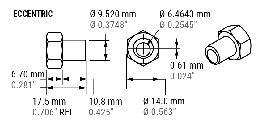
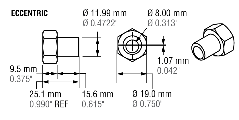
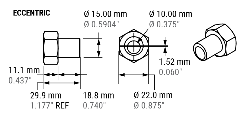
Cam Follower Eccentric
Cam Follower Rollers are easy to mount and are ideal for numerous cam or track roller applications involving moderate loading and shock. They are recommended for applications where the stud hole can be accurately machined to within +0.0000" and -0.0005". Eccentric style Cam Followers should be used when these tolerances cannot be held.
Cam Follower Rollers are composed of high carbon and chromium bearing steel through-hardened and ground outer raceways. The studs and inner races are low carbon alloy steel carburized, and induction hardened.
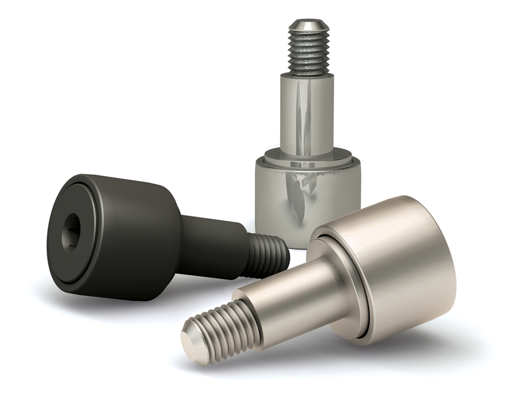
Both eccentric and concentric are available in chrome plated or 440c stainless steel with a high temp version as an option.
Eccentric Cam Followers are designed for situations where maintaining tight tolerances on the mounting holes may be challenging. It features an eccentric lip that fits with a corresponding lip on the bearing's inner ring.
Note: Eccentric Cam Followers are not recommended for applications with reversing rotation.
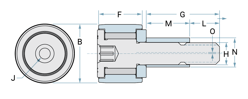
Roller Follower Eccentric Studded
| Part No. | Material | B | J | F | G | H | L | M | N | O |
|---|---|---|---|---|---|---|---|---|---|---|
| 6300063 | Steel | 0.500" | 0.125" | 0.3725" | 0.625" | 0.190" | 0.255" | 0.370" | 0.250" | 0.010" |
| 6300066 | Steel | 0.625" | 0.125" | 0.4350" | 0.750" | 0.250" | 0.318" | 0.432" | 0.375" | 0.015" |
| 6300080 | Chrome Plated | 0.500" | 0.125" | 0.3725" | 0.625" | 0.190" | 0.255" | 0.370" | 0.250" | 0.010" |
| 6300081 | High Temp | 0.500" | 0.125" | 0.3725" | 0.625" | 0.190" | 1.255" | 0.370" | 0.250" | 0.010" |
| 6300086 | Chrome Plated | 0.625" | 0.125" | 0.4355" | 0.750" | 0.259" | 0.313" | 0.432" | 0.375" | 0.015" |
| 6300093 | Stainless Steel | 0.625" | 0.125" | 0.4355" | 0.750" | 0.250" | 0.313" | 0.432" | 0.375" | 0.015" |
| 6300096 | Steel | 1.125" | 0.250" | 0.6225" | 1.000" | 0.438" | 0.505" | 0.495" | 0.625" | 0.030" |
| 6300097 | Steel | 0.875" | 0.188" | 0.4975" | 0.875" | 0.375" | 0.380" | 0.495" | 0.500" | 0.015" |
| Part No. | Threads | Radial Load X (lb) | Static Load Y (lb) | Weight (g) |
|---|---|---|---|---|
| 6300063 | 10-32 UNF-2A | 680 | 790 | 11.34 |
| 6300066 | 10-28 UNF-2A | 955 | 1,215 | 24.95 |
| 6300080 | 10-32 UNF-2A | 680 | 790 | 11.34 |
| 6300081 | 10-32 UNF-2A | 680 | 790 | 11.34 |
| 6300093 | 1/4-28 - 3A | 796 | 972 | 22.68 |
| 6300096 | 7/16-20 UNF 2A | 2,225 | 3,060 | 104.32 |
| 6300097 | 3/8-24 UNF 2A | 1,660 | 2,065 | 104.32 |
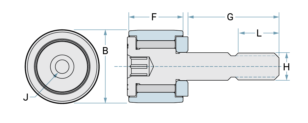
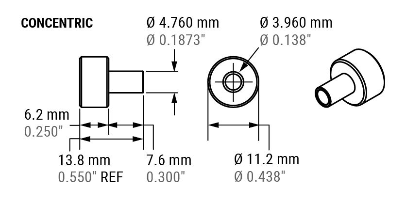
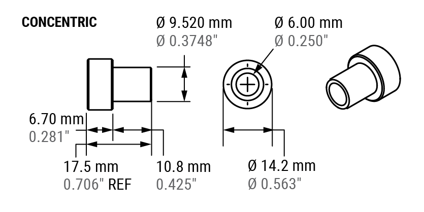
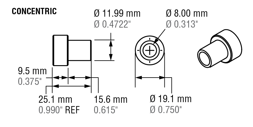
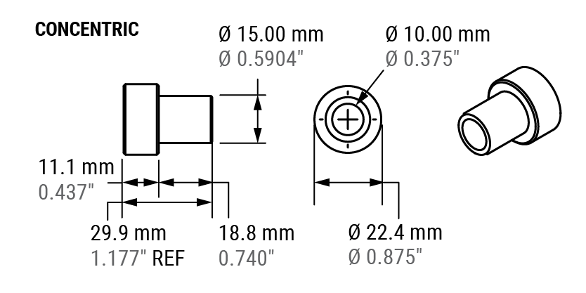
Cam Follower Concentric
Features/ Benefits
- Precision manufacturing to minimize bearing failure which results in costly shutdowns
- Sealed bearings retain lubrication and prevent contamination
- Dimensionally Interchangeable with other standard Cam followers
Concentric Cam Followers include a concentric collar which acts as a locking mechanism. The collar centers the bearing bore which reduces vibration and prevents shaft run out during operation
Cam Followers come pre-lubricated. This lubrication is suitable for applications between 5ºF–275ºF (-15ºC–135ºC) and is equipped with corrosion-resistant additives. The rollers can be relubricated via lube holes and lube groove in the inner race bore.
Lubrication
Cam Followers come pre-lubricated. This lubrication is suitable for applications between 5ºF–275ºF (-15ºC–135ºC) and is equipped with corrosion-resistant additives. The rollers can be relubricated via lube holes and lube groove in the inner race bore.
Roller Follower Concentric Studded
| Part No. | Material | B | J | F | G | H | L |
|---|---|---|---|---|---|---|---|
| 6300062 | Steel | 0.500" | 0.125" | 0.3725" | 0.625" | 0.191" | 0.250" |
| 6300065 | Steel | 0.625" | 0.125" | 0.4350" | 0.750" | 0.251" | 0.313" |
| 6300078 | Stainless Steel | 0.500" | 0.125" | 0.3725" | 0.625" | 0.191" | 0.250" |
| 6300079 | High Temp | 0.500" | 0.125" | 0.3725" | 0.625" | 0.191" | 0.250" |
| 6300084 | Chrome Plated | 0.625" | 0.125" | 0.4355" | 0.750" | 0.251" | 0.313" |
| 6300085 | Stainless Steel | 0.625" | 0.125" | 0.4350" | 0.750" | 0.251" | 0.313" |
| Part No. | Threads | Radial Load X (lb) | Static Load Y (lb) | Weight (g) |
|---|---|---|---|---|
| 6300062 | 10-32 UNF-2A | 680 | 790 | 11.34 |
| 6300065 | 10-28 UNF-2A | 955 | 1,215 | 20.41 |
| 6300078 | 10-32 UNF-2A | 300 | 610 | 11.34 |
| 6300079 | 10-32 UNF-2A | 680 | 790 | 11.34 |
| 6300084 | 1/4-28 - 3A | 995 | 1,215 | 20.41 |
| 6300085 | 10-28 UNF-2A | 796 | 972 | 20.41 |
| 6300086 | 1/4-28 - 3A | 995 | 1,215 | 22.68 |
V-Guide Wheels, Rails & Bushings
Features/ Benefits
V-Guide systems are an industry standard for linear motion, and offer features that make them an ideal solution for a wide range of motion control applications.
- Radial loads up to 9.9 kN (2,246 lb.) per wheel
- Axial loads up to 2.3 kN (520 lb.) per wheel
- Precision dual row angular contact design
- Operating temperature range from -20°C to 80°C (-4°F to 176°F)
- Concentric or eccentric wheel bushings in inch and metric sizing
1. Induction Hardened
Rails in long lengths
2. Wheel Bushings
Adjustable or fixed

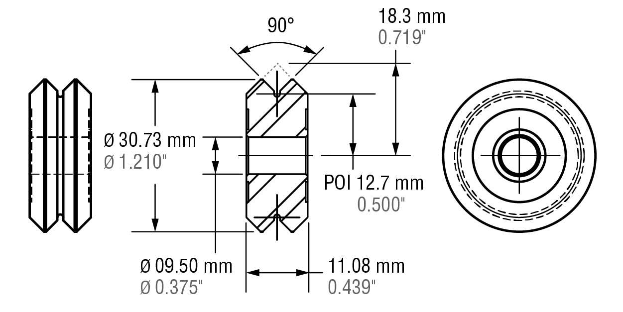
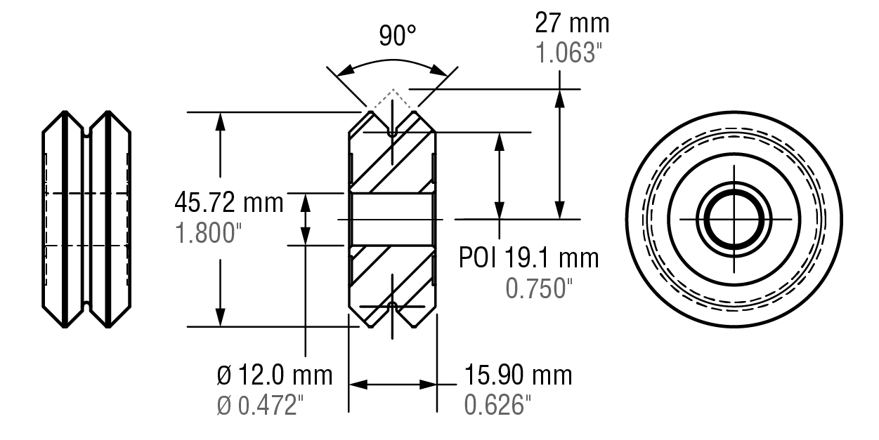
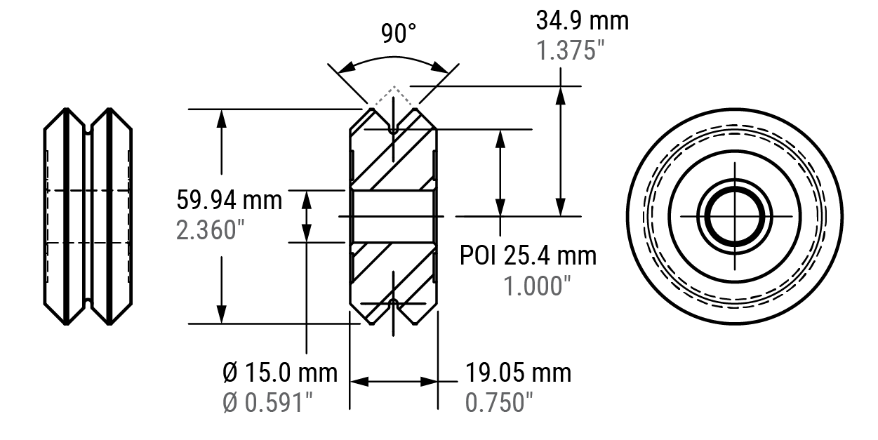
V-Guide Wheels
V-Guide wheels are precision ground, dual row angular contact ball bearings with hardened outer way surfaces that provide low friction guidance for linear motion applications. They can be used with internal or external 90-degree ways – or used with round shafts.
- Four sizes
- Permanently sealed and lubricated
- Precision dual row bearing construction
- Available in 52100 bearing steel or 420 stainless steel construction
- 304 stainless steel shields or nitrile rubber seals
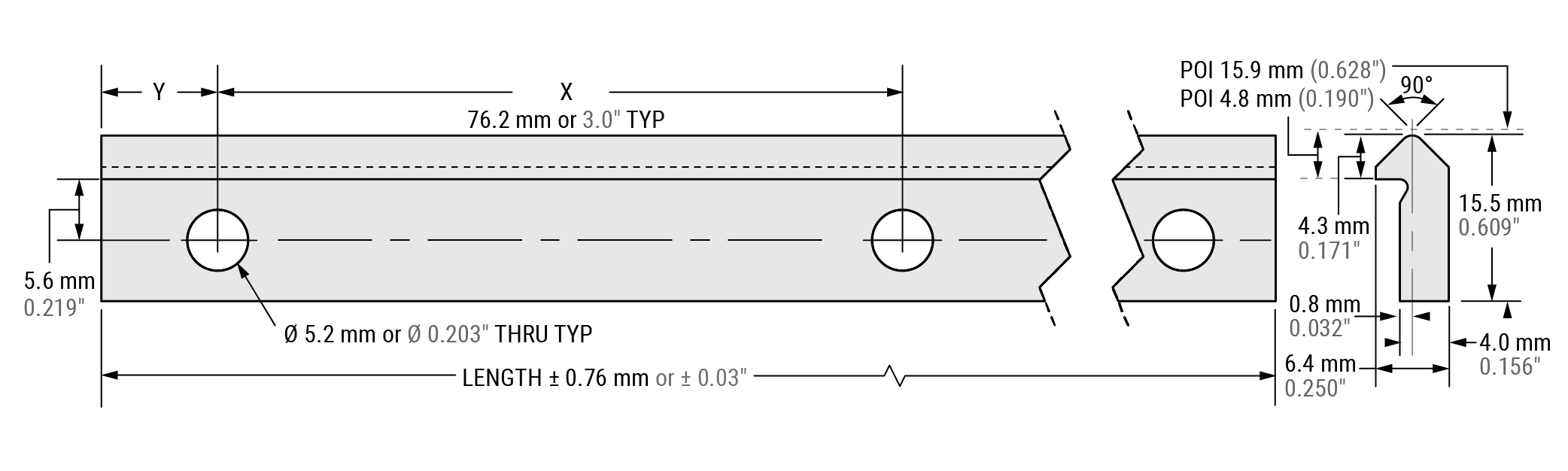
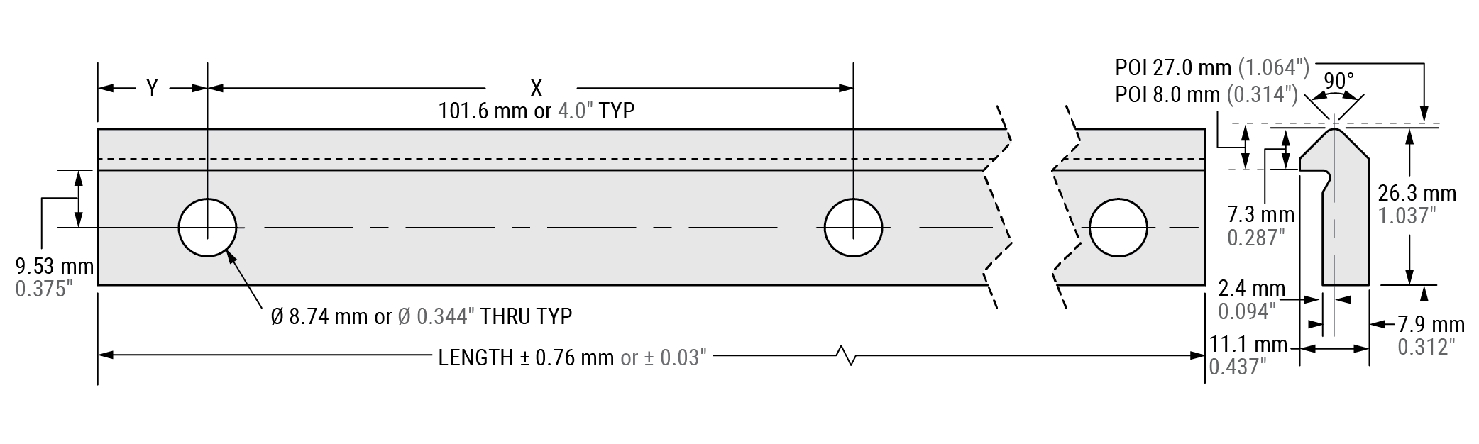
V-Guide Rail
Rails are induction hardened, ground, and polished. The track body is left soft for easy drilling of mounting holes. Four sizes are designed to correspond with wheel sizes.
- Has shoulder for simple mounting and alignment
- Induction hardened way surface
- 1045 carbon steel or 400 series stainless steel
- Optional black oxide finish
- Rails are cut to length, MAX length up to 5,486.4 mm (216")
Wheel Bushings
- 303 stainless steel construction
- Inch or metric hardware
- Adjustable bushings allow adjustable fit and preload
- Fixed bushings are used in the primary radial load direction
| V Guide Wheel |
Size | Weight | Per Wheel Radial Load |
Axial Load | |||||
|---|---|---|---|---|---|---|---|---|---|
| mm | in. | G | oz. | N | lb. | N | lb. | ||
| Size 1 | VW1 | 20 | 3/4 | 12 | 0.42 | 1,260 | 283 | 297 | 67 |
| Size 2 | VW2 | 30 | 1 1/4 | 40 | 1.41 | 2,730 | 614 | 632 | 142 |
| Size 3 | VW3 | 45 | 1 3/4 | 136 | 4.79 | 6,166 | 1,386 | 1,448 | 326 |
| Size 4 | VW4 | 60 | 2 1/4 | 285 | 10 | 9,991 | 2,246 | 2,313 | 520 |
Online Configurator
1:1 Scale
Size 1: VW1
Size 2: VW2
Size 3: VW3
Size 4: VW4
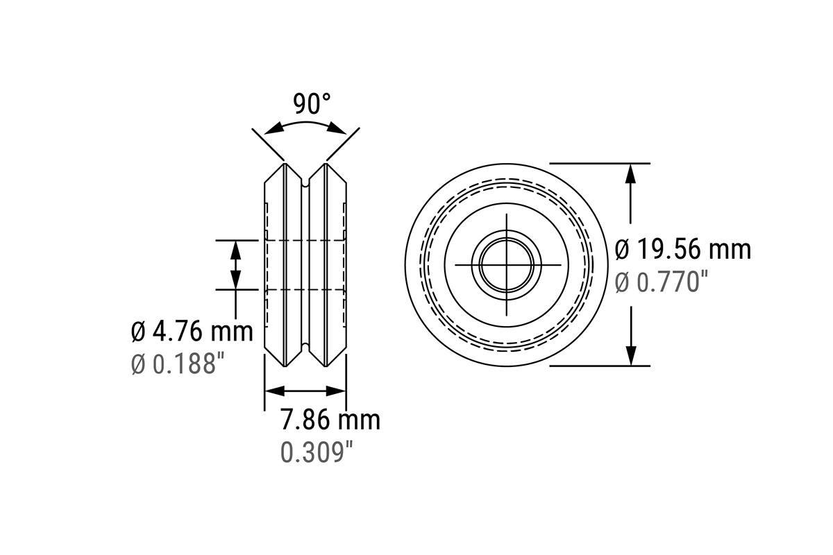
V-Guide Size 1 • 20 mm (3/4")
Radial loads up to 283 lb. (1,260 N) per wheel
Axial loads up to 67 lb. (297 N) per wheel
Wheel weight: .42 oz. (12 g)
Speed rating: 16,000 rpm MAX (13.23 m/s MAX)
V-Guide Wheels
| VW1 | Shielded Bearing |
| VWS1 | Sealed Bearing |
| VWSS1 | Sealed Stainless Bearing |
Wheel Bushings
| Inch Series | |
|---|---|
| VB1 | Concentric Fixed Bushing |
| VBA1 | Eccentric Adjustable Bushing |
| Metric Series | |
|---|---|
| MVB1 | Concentric Metric Fixed Bushing |
| MVBA1 | Eccentric Metric Adjustable Bushing |
V-Guide Rail
| Carbon Steel | |
|---|---|
| VR1-xxx.xxx | undrilled rail, MAX length 216” (5,486.4 mm) |
| VRD1-xxx.xxx | drilled rail |
| Stainless Steel | |
|---|---|
| VRS1-xxx.xxx | undrilled rail, MAX length 216" (5,486.4 mm) |
| VRSD1-xxx.xxx | drilled rail |
Note: Non-heat treated rails available in all sizes, contact factory.
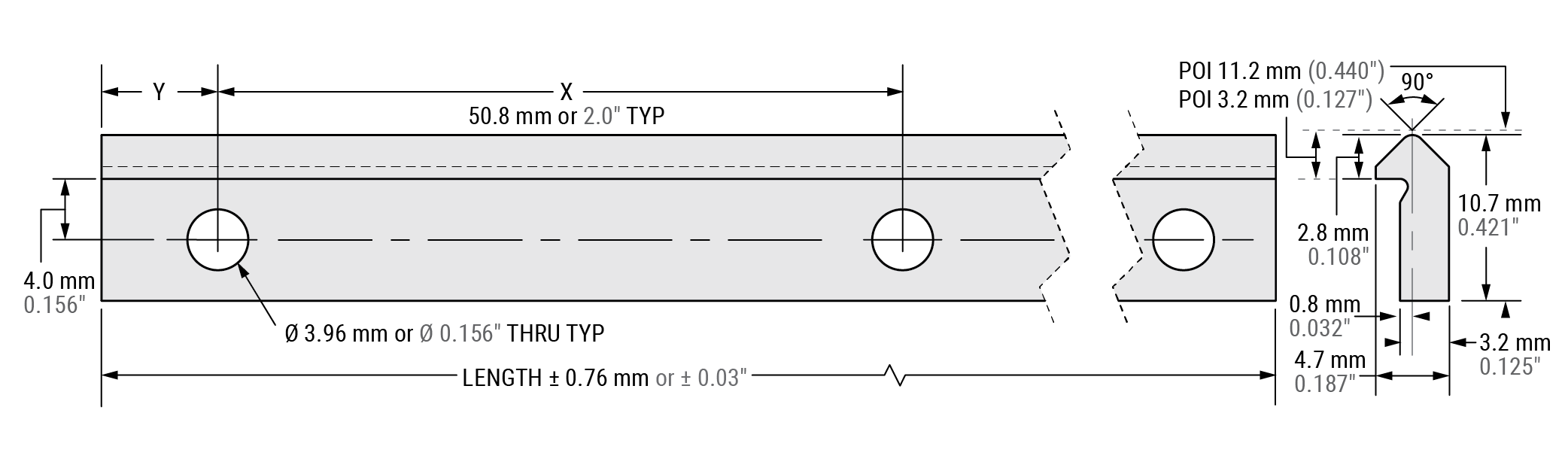
POI = Point of intersection;
Specify Y dimension (hole to end) at time of order
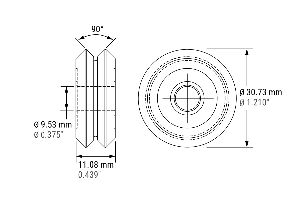
V-Guide Size 2 • 30 mm (1-1/4”)
Radial loads up to 614 lb. (2,730 N) per wheel
Axial loads up to 142 lb. (632 N) per wheel
Wheel weight: 1.3 oz. (38 g)
Speed rating: 9,600 rpm MAX (12.76 m/s MAX)
V-Guide Wheels
| VW2 | Shielded Bearing |
| VWS2 | Sealed Bearing |
| VWSS2 | Sealed Stainless Bearing |
Wheel Bushings
| Inch Series | |
|---|---|
| VB2 | Concentric Fixed Bushing |
| VBA2 | Eccentric Adjustable Bushing |
| Metric Series | |
|---|---|
| MVB2 | Concentric Metric Fixed Bushing |
| MVBA2 | Eccentric Metric Adjustable Bushing |
V-Guide Rail
| Carbon Steel | |
|---|---|
| VR2-xxx.xxx | undrilled rail, MAX length 216” (5,486.4 mm) |
| VRD2-xxx.xxx | drilled rail |
| Stainless Steel | |
|---|---|
| VRS2-xxx.xxx | undrilled rail, MAX length 216" (5,486.4 mm) |
| VRSD2-xxx.xxx | drilled rail |
Note: Non-heat treated rails available in all sizes, contact factory.
POI = Point of intersection;
Specify Y dimension (hole to end) at time of order
V-Guide Size 3 • 45 mm (1-3/4")
Radial loads up to 1,386 lb. (6,166 N) per wheel
Axial loads up to 326 lb. (1,448 N) per wheel
Wheel weight: 4.6 oz. (131 g)
Speed rating: 8,000 rpm MAX (16.00 m/s MAX)
V-Guide Wheels
| VW3 | Shielded Bearing |
| VWS3 | Sealed Bearing |
| VWSS3 | Sealed Stainless Bearing |
Wheel Bushings
| Inch Series | |
|---|---|
| VB3 | Concentric Fixed Bushing |
| VBA3 | Eccentric Adjustable Bushing |
| Metric Series | |
|---|---|
| MVB3 | Concentric Metric Fixed Bushing |
| MVBA3 | Eccentric Metric Adjustable Bushing |
V-Guide Rail
| Carbon Steel | |
|---|---|
| VR3-xxx.xxx | undrilled rail, MAX length 216” (5,486.4 mm) |
| VRD3-xxx.xxx | drilled rail |
| Stainless Steel | |
|---|---|
| VRS3-xxx.xxx | undrilled rail, MAX length 216" (5,486.4 mm) |
| VRSD3-xxx.xxx | drilled rail |
Note: Non-heat treated rails available in all sizes, contact factory.

POI = Point of intersection;
Specify Y dimension (hole to end) at time of order
V-Guide Size 4 • 60 mm (2-1/4”)
Radial loads up to 2,246 lb. (9,991 N) per wheel
Axial loads up to 520 lb. (2,313 N) per wheel
Wheel weight: 10 oz. (281 g)
Speed rating: 5,000 rpm MAX (13.30 m/s MAX)
V-Guide Wheels
| VW4 | Shielded Bearing |
| VWS4 | Sealed Bearing |
| VWSS4 | Sealed Stainless Bearing |
Wheel Bushings
| Inch Series | |
|---|---|
| VB4 | Concentric Fixed Bushing |
| VBA4 | Eccentric Adjustable Bushing |
| Metric Series | |
|---|---|
| MVB4 | Concentric Metric Fixed Bushing |
| MVBA4 | Eccentric Metric Adjustable Bushing |
V-Guide Rail
| Carbon Steel | |
|---|---|
| VR4-xxx.xxx | undrilled rail, MAX length 216” (5,486.4 mm) |
| VRD4-xxx.xxx | drilled rail |
| Stainless Steel | |
|---|---|
| VRS4-xxx.xxx | undrilled rail, MAX length 216" (5,486.4 mm) |
| VRSD4-xxx.xxx | drilled rail |
Note: Non-heat treated rails available in all sizes, contact factory.
POI = Point of intersection;
Specify Y dimension (hole to end) at time of order
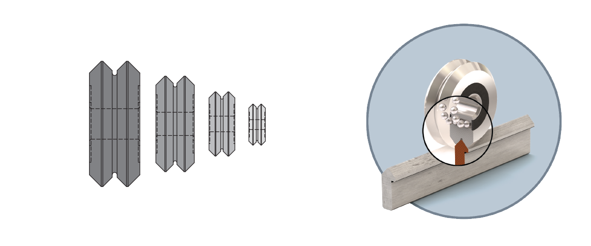
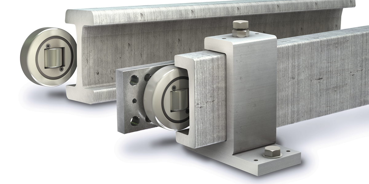
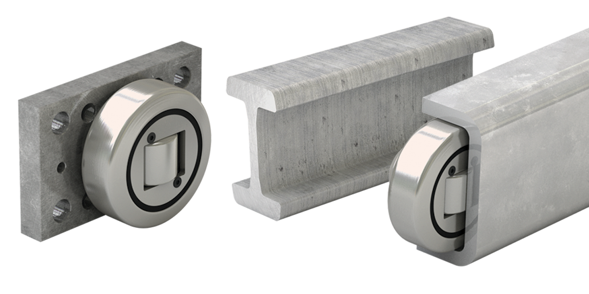
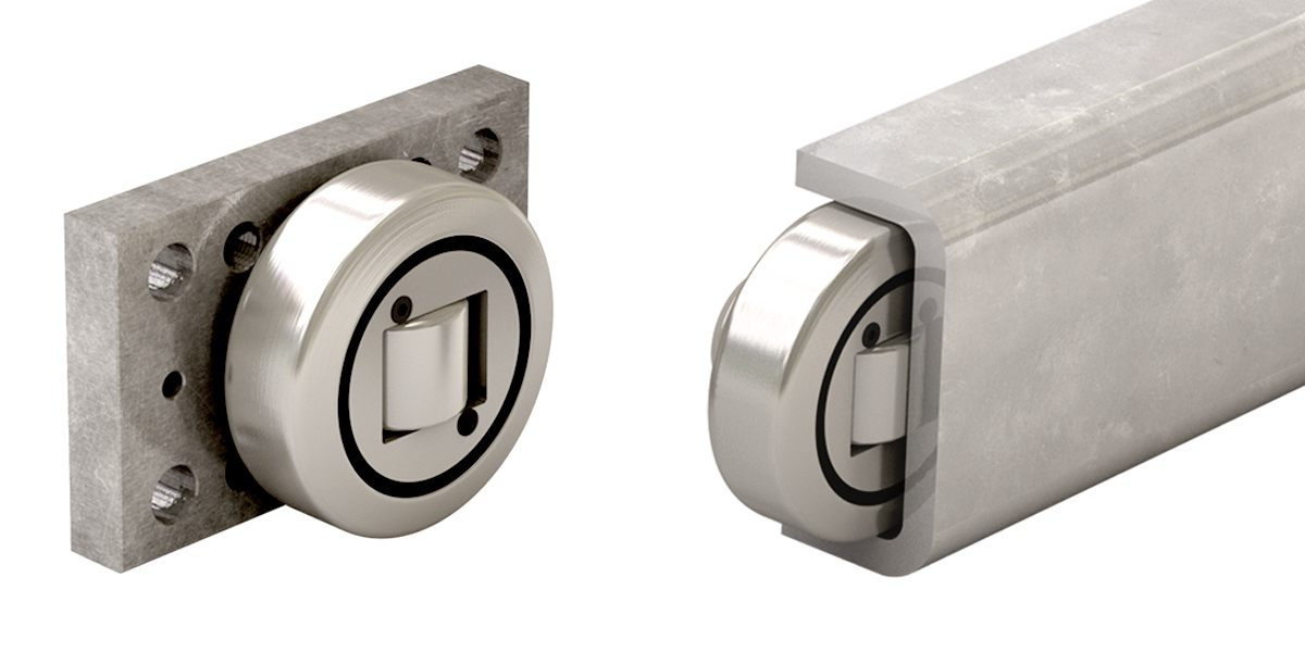
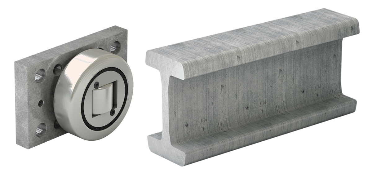
Hevi-Rail Linear Guide
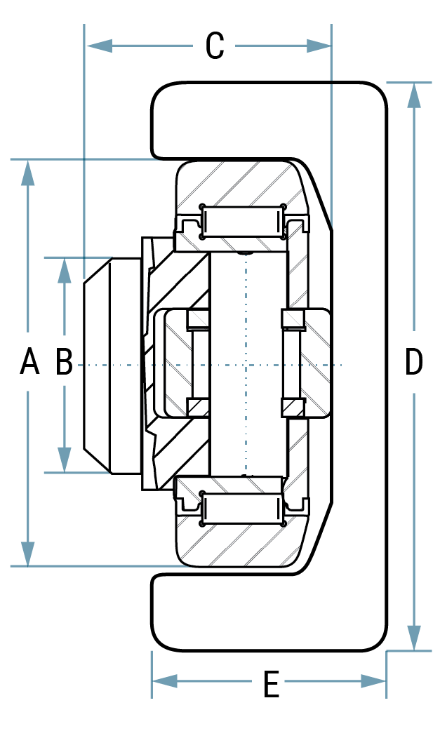
Features/Benefits
The economical Hevi-Rail® guide systems offer a lifetime of durability under continuous use. The easily interchangeable bearing components provide even dispersion of forces in the rails for longer system life and stability
Linear Bearings
- Outer ring made of case-hardened steel
- Handles very high axial and radial loads
- Easily interchangeable components for less down-time
- Fixed and adjustable combined bearings available
Rails
- Standard length up to 6 meters
- Sand blasted or lightly oiled options available
- U-channel or I-channel available
Clamp Flanges
- Eliminates need for welding and straightening
- Easily adjustable parallelism
Flange Plates
- Simple mounting for bearings
- Can be ordered pre-welded to bearing
| Combined Hevi-Rail Bearing |
Rail | Flange Plate |
Clamp Flange |
Bearing with welded flange plate* |
System MAX Static Load** kN |
General Dimensions*** mm |
||||||||
|---|---|---|---|---|---|---|---|---|---|---|---|---|---|---|
| Fixed | Adjustable | U-Channel | I-Channel | fixed | adjustable | Radial | Axial | A | B | C | D | E | ||
| HVB-053 | – | HVR-S | – | HVPS-1 | – | HVB-053/HVPS | – | 5.23 | 1.68 | 52.5 | 30 | 33.0 | 65.0 | 30.0 |
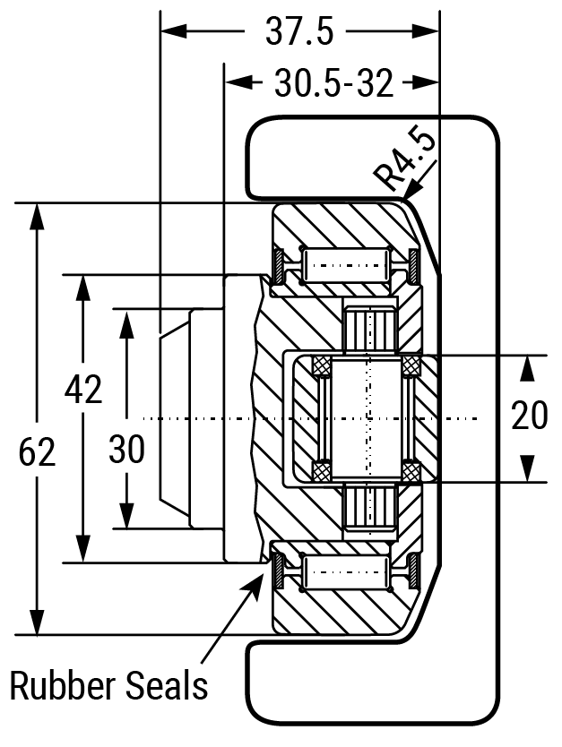
| HVB-054 | HVBEA-454 | HVR-0 | – | HVP0-1 | HVC-0 | HVB-054/HVP0 | HVBEA-454/HVP0 | 10.30 | 3.20 | 62.0 | 30 | 37.5 | 86.5 | 36.0 |
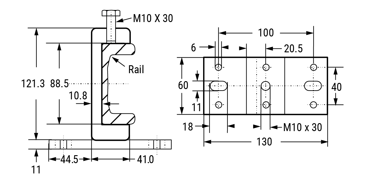
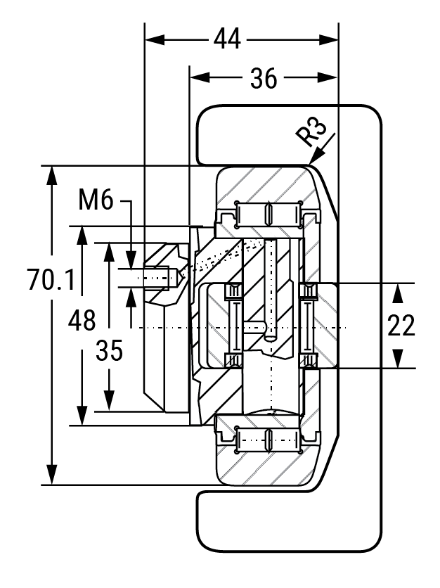
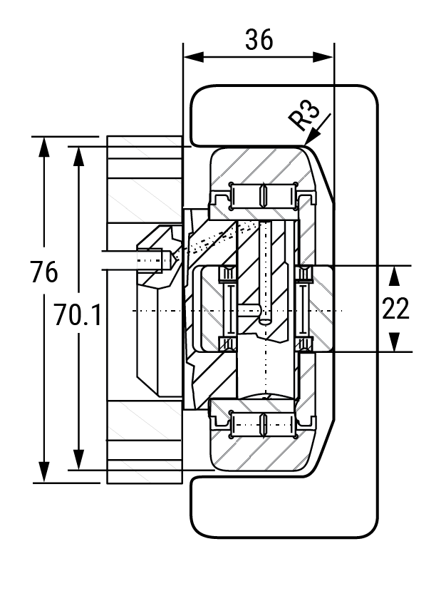
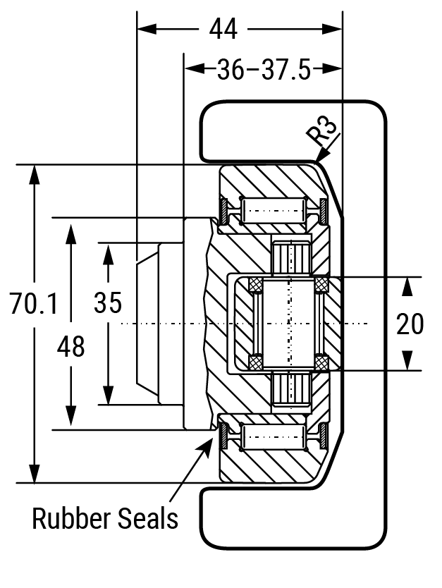
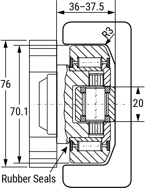
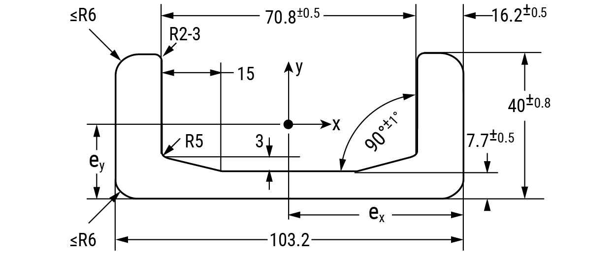
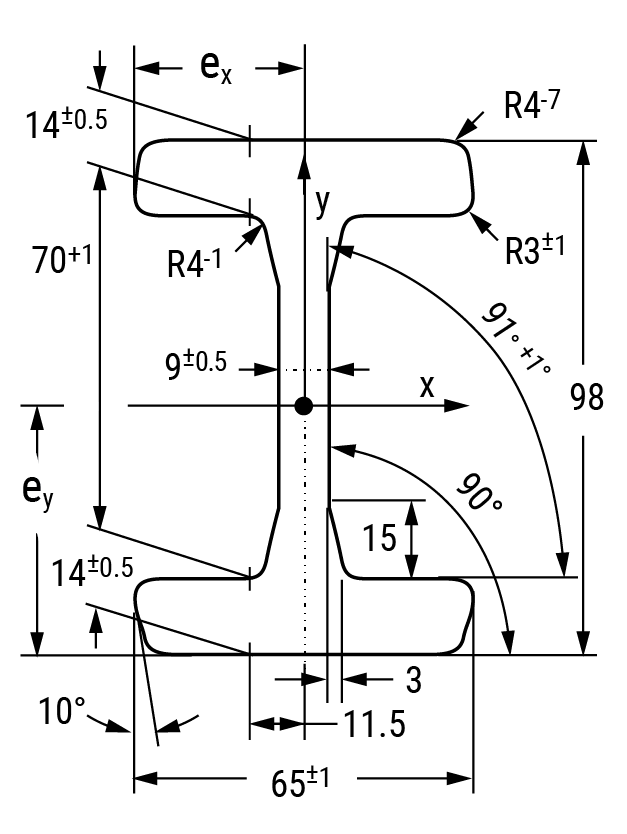
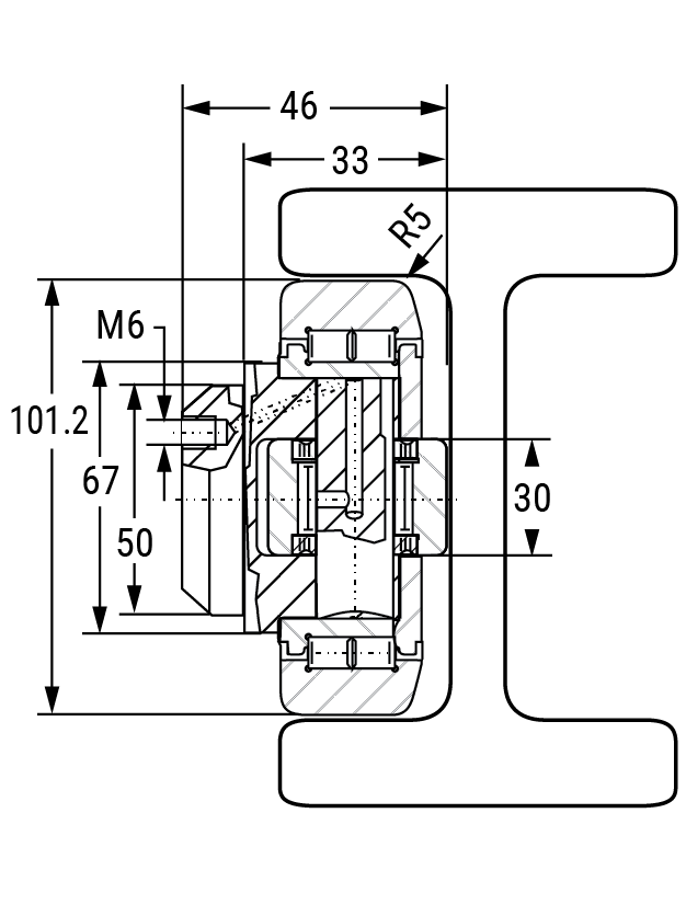
| HVB-055 | HVBEA-455 | HVR-1 | HVRI-07 | HVP1-1 | HVC-1 | HVB-055/HVP1 | HVBEA-455/HVP1 | 12.40 | 3.87 | 70.1 | 35 | 44.0 | 103.2 | 40.0 |
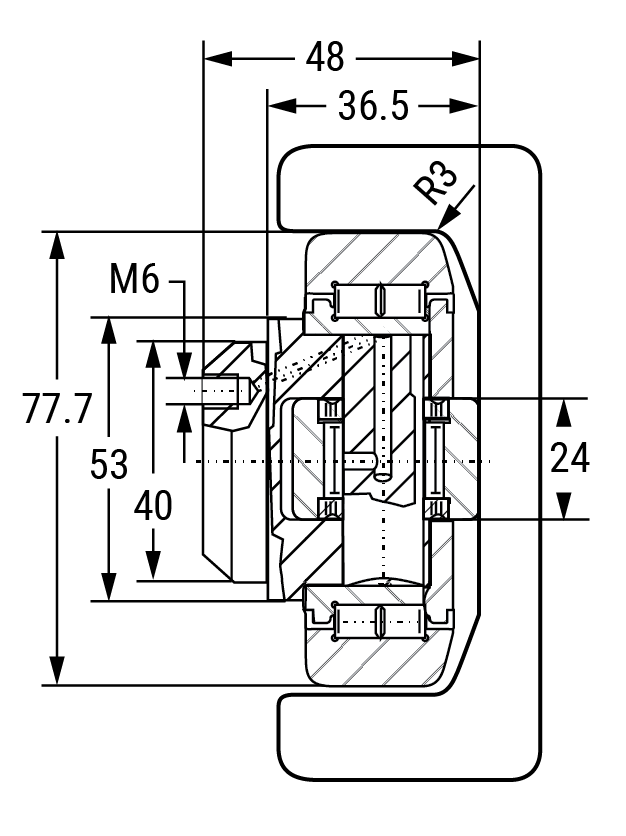
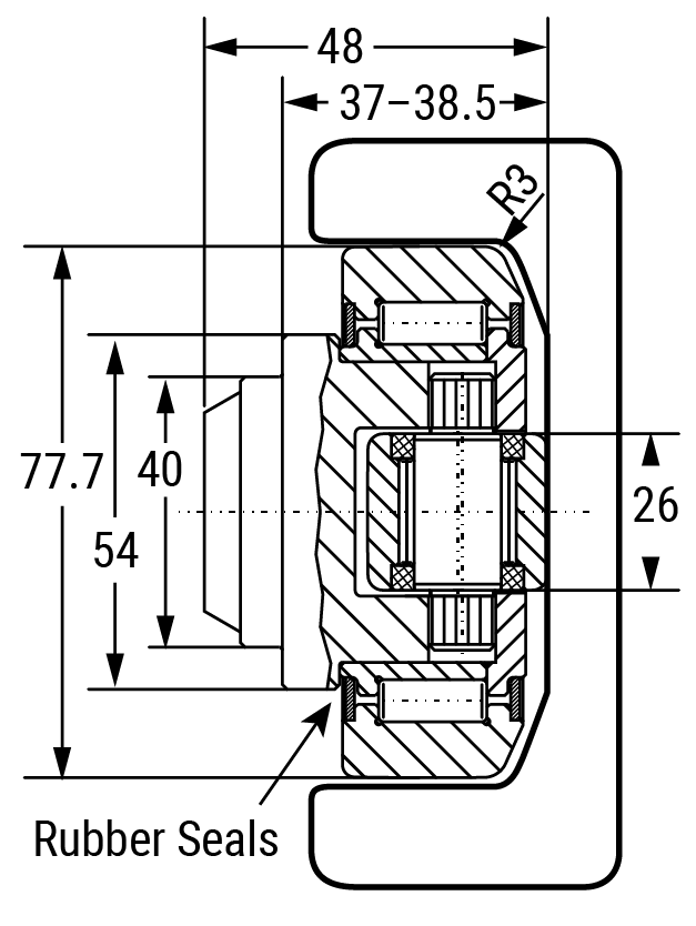
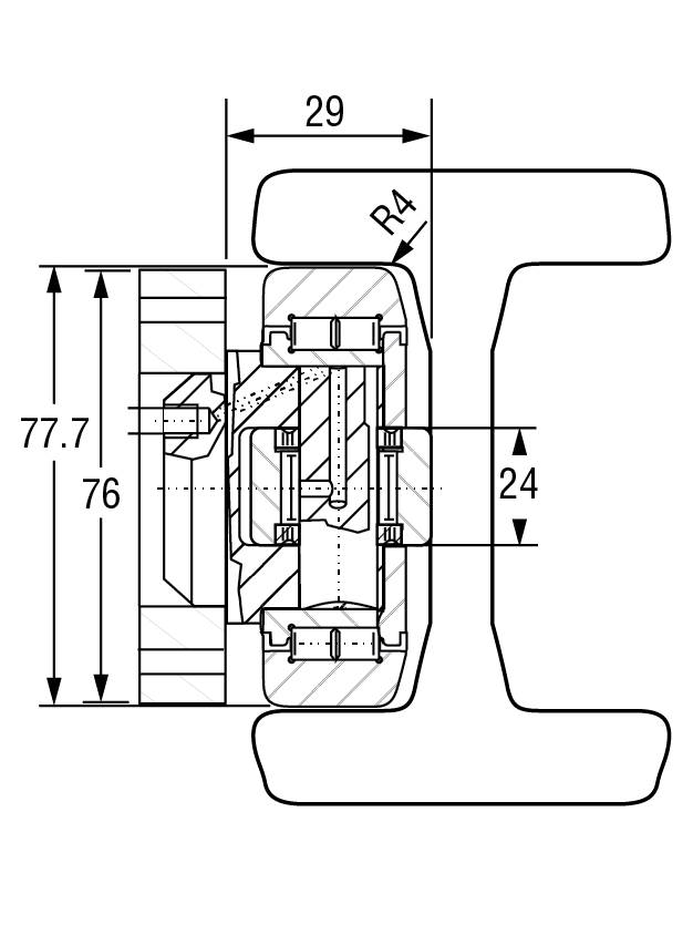
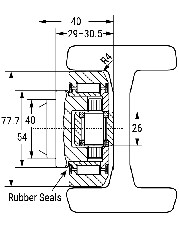
| HVB-056 | HVBEA-456 | HVR-2 | – | HVP2-1 | HVC-2 | HVB-056/HVP2 | HVBEA-456/HVP2 | 12.90 | 4.00 | 77.7 | 40 | 48.0 | 121.3 | 41.0 |
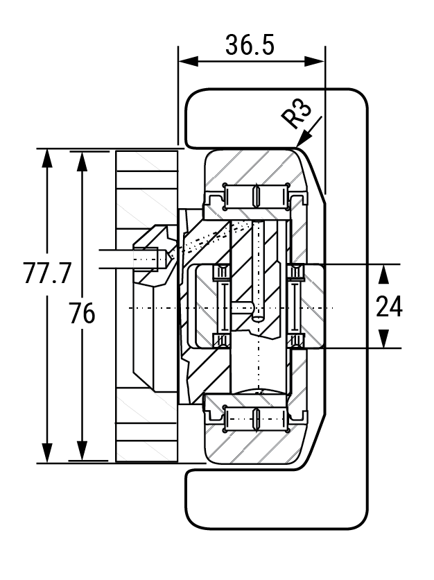
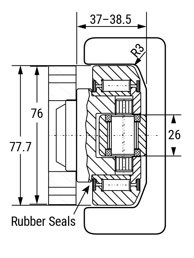
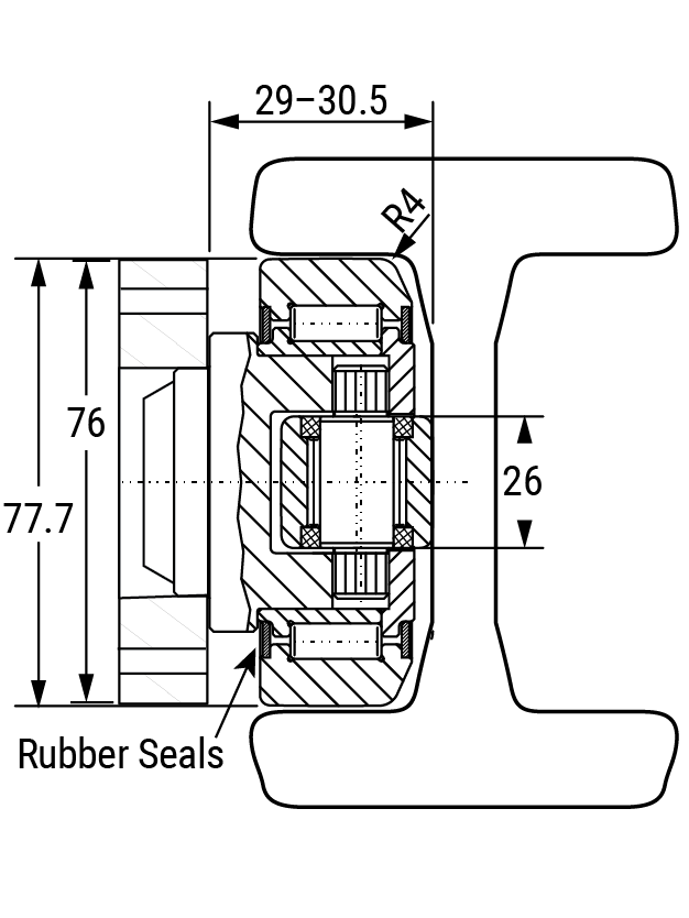
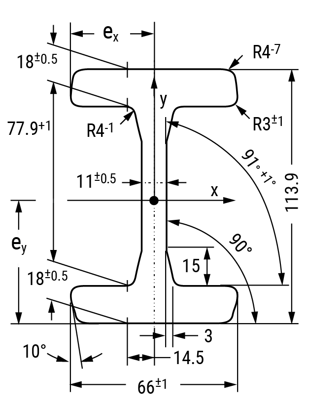
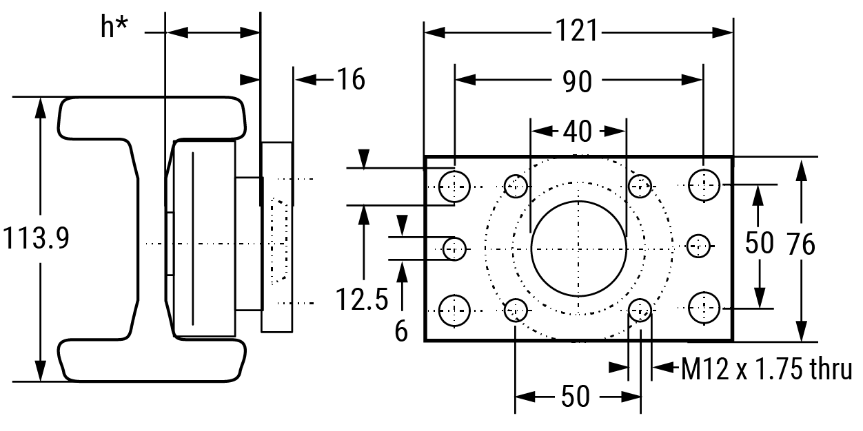
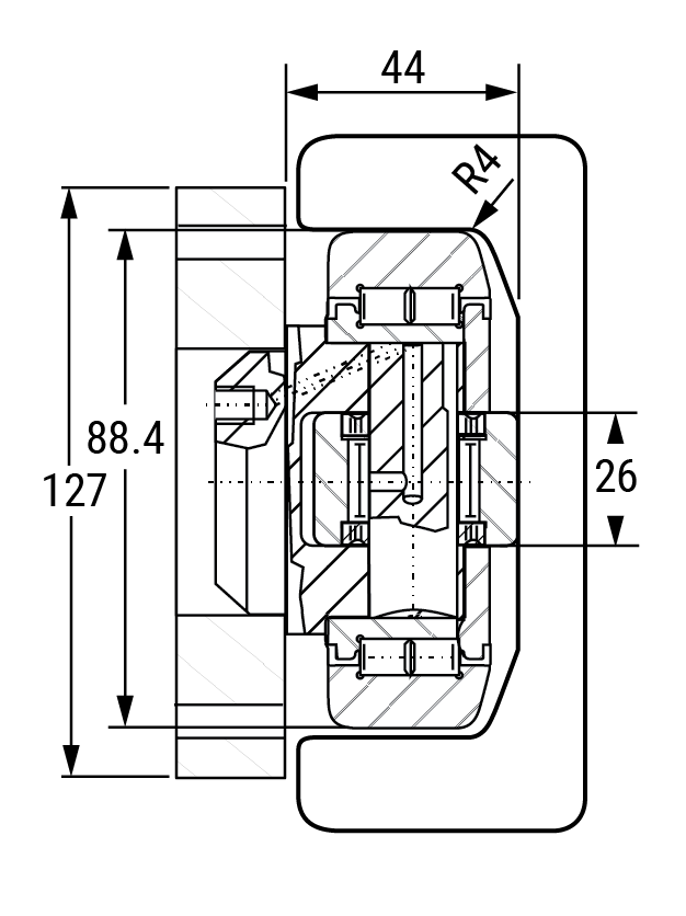
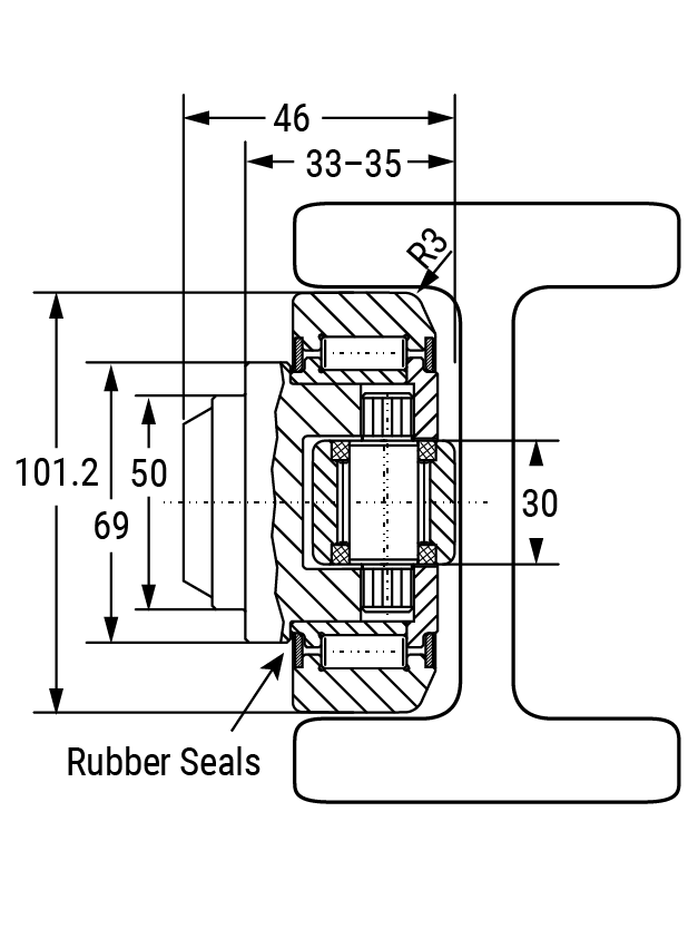
| HVB-057 | HVBEA-457 | – | HVRI-08 | HVP2-1 | – | HVB-057/HVP2 | HVBEA-457/HVP2 | 12.90 | 4.00 | 77.7 | 40 | 40.7 | 113.9 | 66.0 |
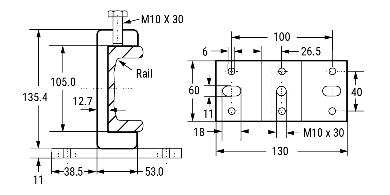
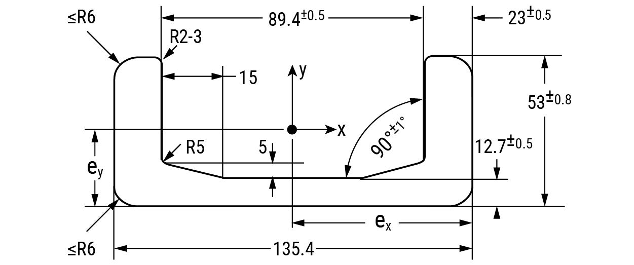
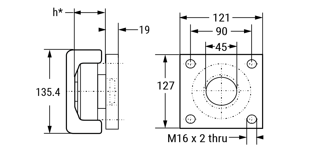
| HVB-058 | HVBEA-458 | HVR-3 | HVRI-09 | HVP3-1 | HVC-3 | HVB-058/HVP3 | HVBEA-458/HVP3 | 22.40 | 7.00 | 88.4 | 45 | 57.0 | 135.4 | 53.0 |
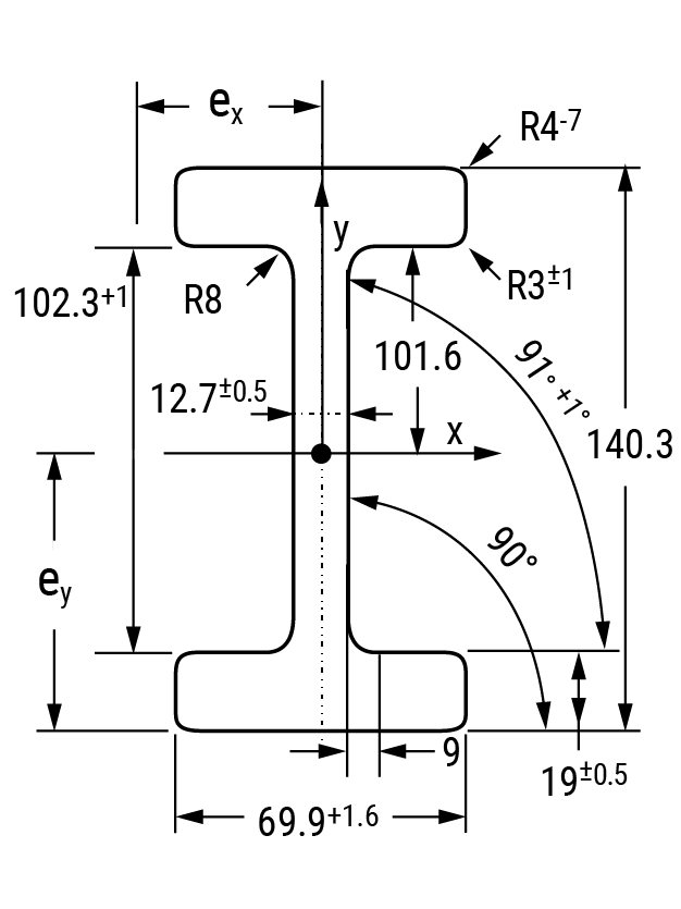
| HVB-059 | HVBEA-459 | – | HVRI-10 | – | – | – | – | 22.00 | 7.00 | 101.2 | 50 | 46.0 | 140.3 | 69.9 |
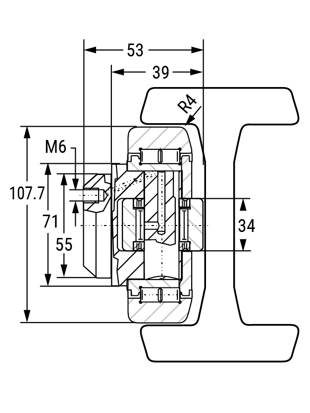
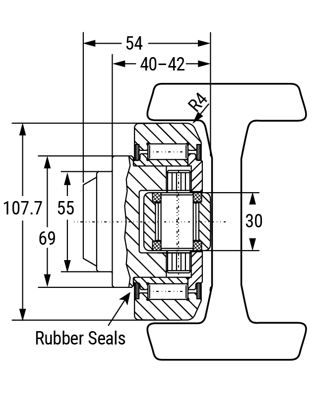
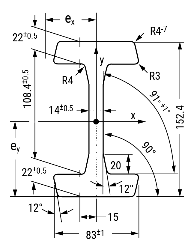
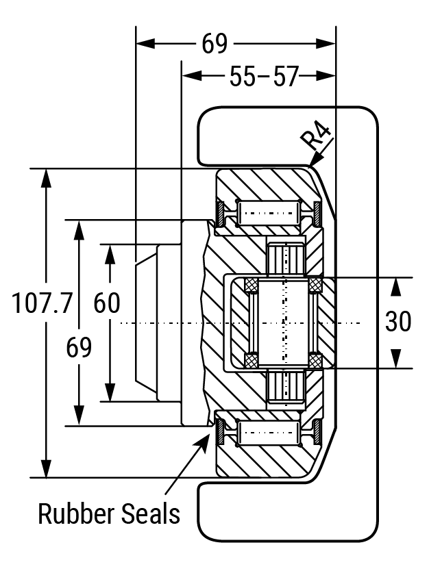
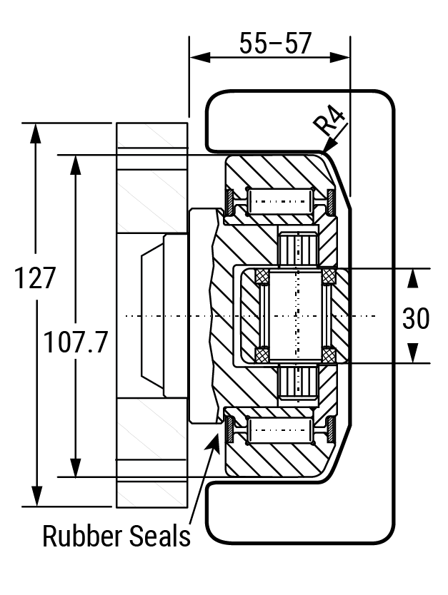
| HVB-060 | HVBEA-460 | – | HVRI-11 | – | – | – | – | 23.80 | 7.44 | 107.7 | 55 | 53.0 | 152.4 | 83.0 |
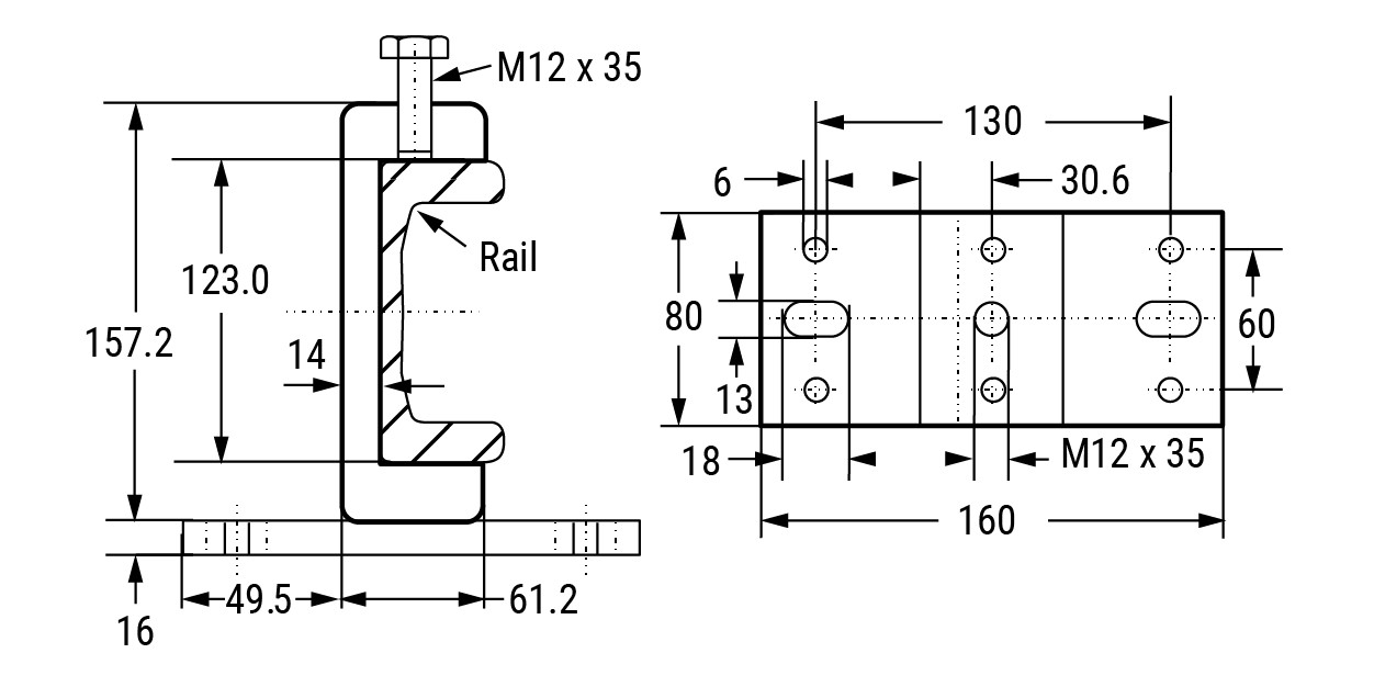
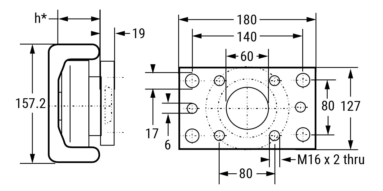
| HVB-061 | HVBEA-461 | HVR-4 | – | HVP4-1 | HVC-4 | HVB-061/HVP4 | HVBEA-461/HVP4 | 23.80 | 7.44 | 107.7 | 60 | 69.0 | 157.2 | 61.2 |
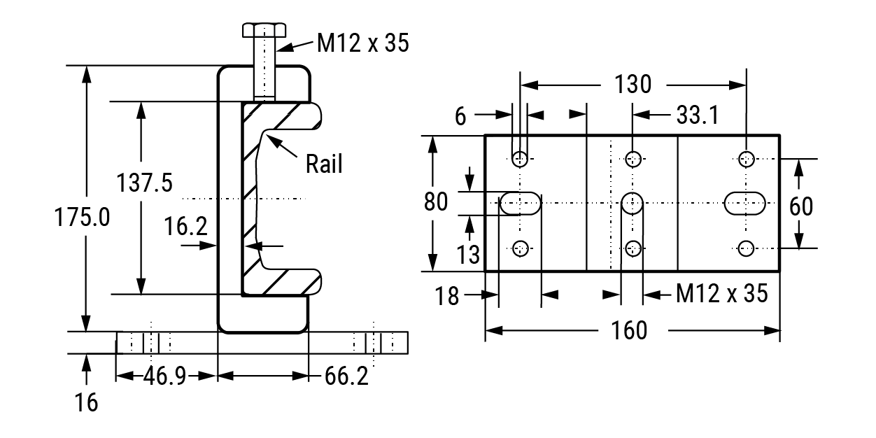
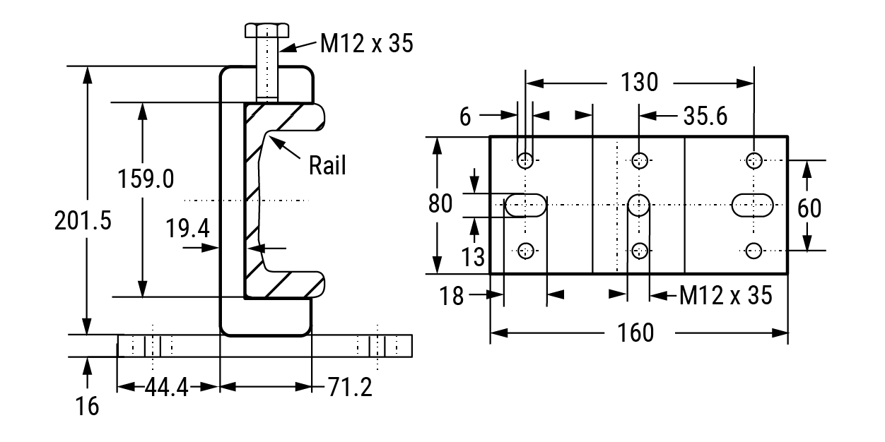
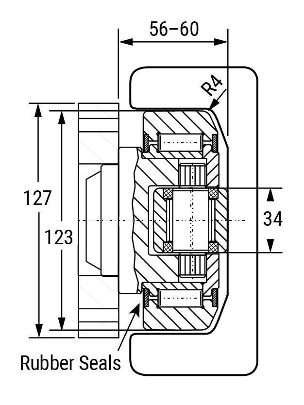
| HVB-062 | HVBEA-462 | HVR-5 | – | HVP4-1 | – | HVB-062/HVP4 | HVBEA-462/HVP4 | 33.90 | 10.60 | 123.0 | 60 | 72.3 | 175.0 | 66.2 |
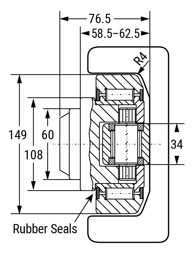
| HVB-063 | HVBEA-463 | HVR-6 | – | HVP6-1 | – | HVB-063/HVP6 | HVBEA-463/HVP6 | 59.20 | 18.50 | 149.0 | 60 | 78.5 | 201.5 | 71.2 |
- *For flange plate oriented 90 degrees to either fixed or adjustable, add -90 to the end of the part number (ex. HVB-053/HVPS-90).
- **System MAX static loads are achievable when used with shown rails.
- ***Detailed dimensions can be found on each product page

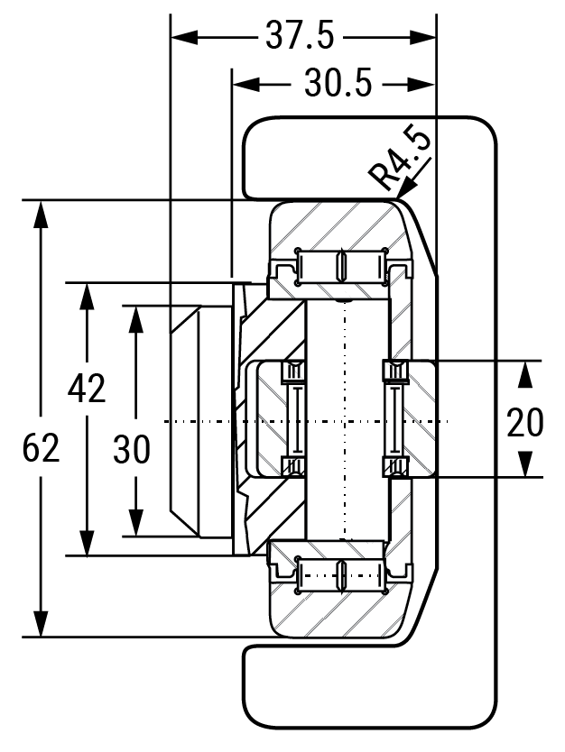
HVB-053 • 0.58 US Ton-Force
Axial Bearing – Fixed HVB-053
Weight = 0.36 kg
Maximum Bearing Loads:
Radial: Dynamic = 24.50 kN; Static = 32.50 kN
Axial: Dynamic = 7.50 kN; Static = 7.50 kN
Note: Above loads achievable when used with a hardened rail HRC 55 minimum 2.54 mm deep
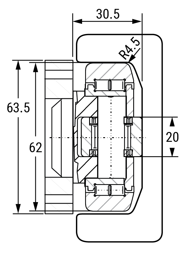
Axial Bearing – Fixed HVB-053/HVPS with Welded Flange plate
System Maximum Static Loads:
Radial: 5.23 kN/0.58 US Ton-Force
Axial: 1.68 kN/0.18 US Ton-Force
Note: Above loads are achievable when used with shown rails.
Note: values do not include stack up tolerances for flange plate and bearing assembly.
Flange Plate HVPS-1
For ordering separate flange plate only
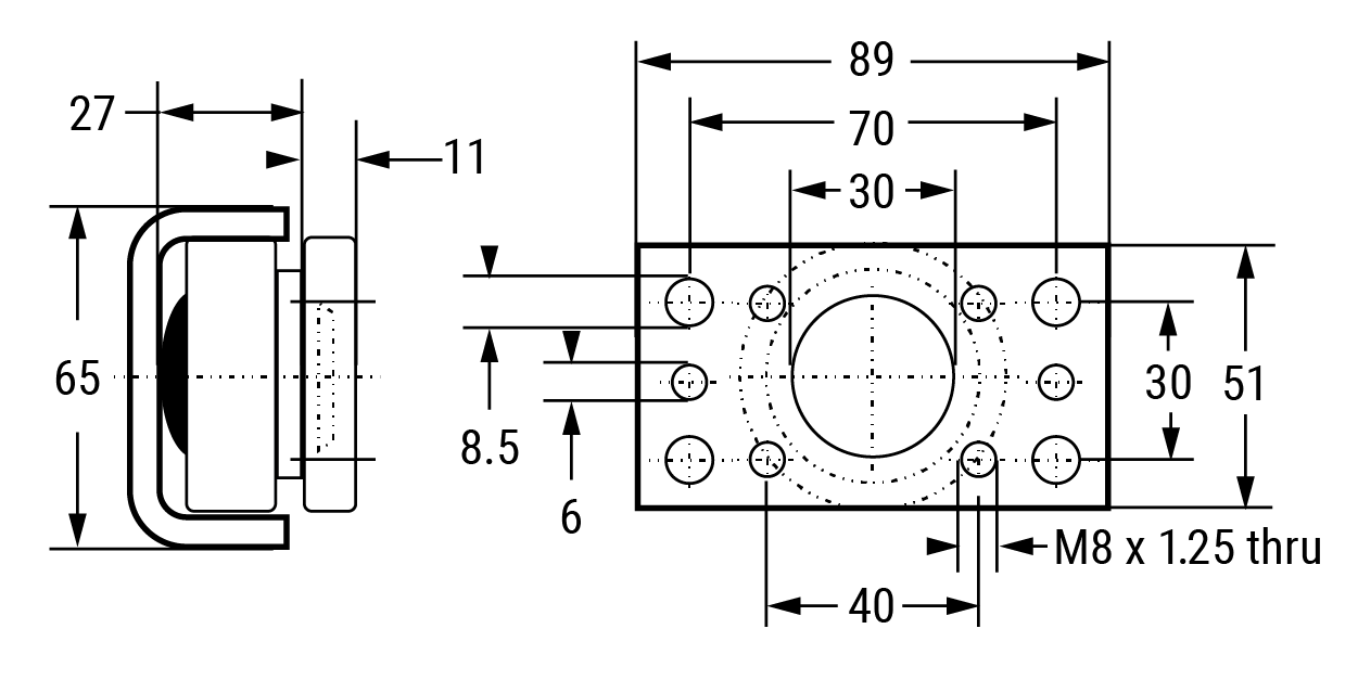
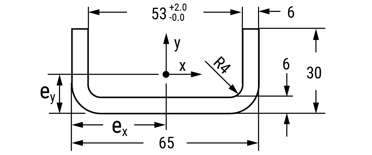
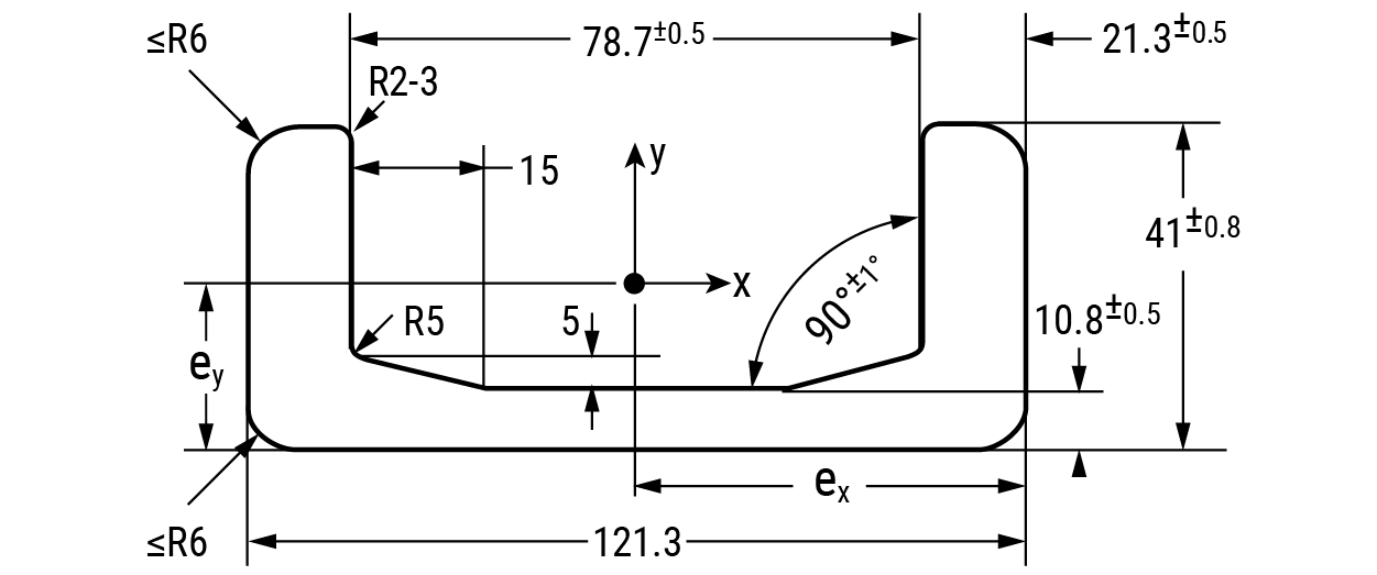
Rail – U Channel HVR-S
Weight = 5.3 kg/m
Moment of Inertia: Ix = 5.2 cm4; Iy = 38.8 cm4
Moment of Resistance: Wx = 2.50 cm3; Wy = 11.90 cm3
Radius of Inertia: ix = 0.80 cm; iy = 2.40 cm
Distance to Center of Gravity: ey = 0.94 cm; ex = 32.50 cm
Ordering Information
| Part No. | Description |
|---|---|
| HVB-053 | Fixed axial bearing |
| HVB-053/HVPS | Fixed axial bearing with welded flange plate |
| HVPS-1 | Flange plate |
| HVR-S | U-channel profile rail for -53 bearings |
Hevi-Rail Top 5 Design Tips
HVB-054 • 1.15 US Ton-Force
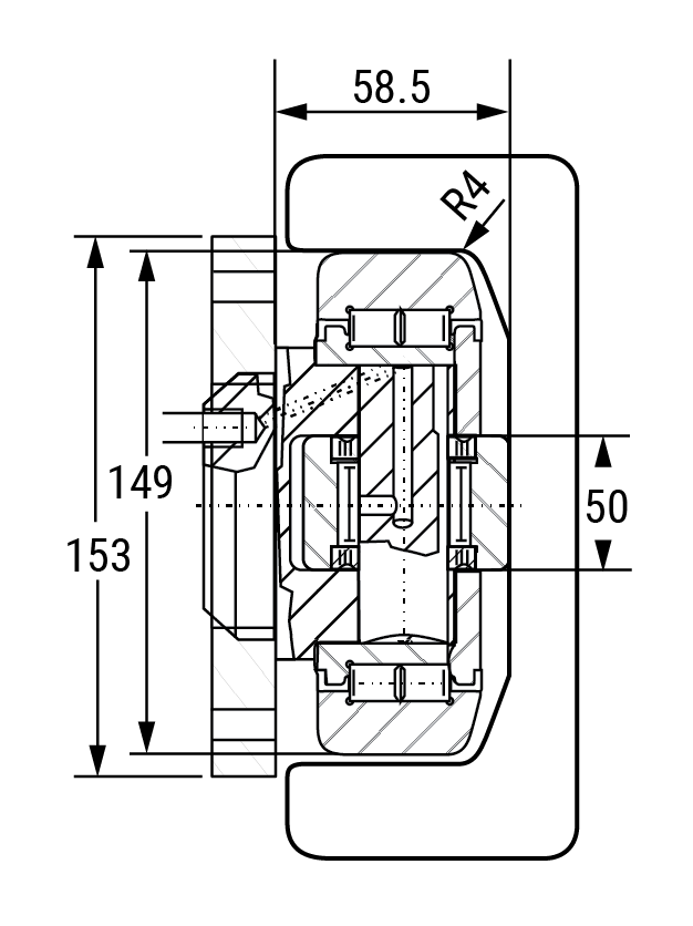
Axial Bearing – Fixed HVB-054
Weight = 0.53 kg
Maximum Bearing Loads:
Radial: Dynamic = 31 kN; Static = 35.5 kN
Axial: Dynamic = 11.50 kN; Static = 11.50 kN
Note: Above loads achievable when used with a hardened rail HRC 55 minimum 2.54 mm deep.
Axial Bearing – Fixed HVB 054/HVP0 With Welded Flange Plate
System Maximum Static Loads:
Radial: 10.3 kN/1.15 US Ton-Force
Axial: 3.2 kN/0.35 US Ton-Force
Note: Above loads are achievable when used with shown rails.
Note: values do not include stack up tolerances for flange plate and bearing assembly.
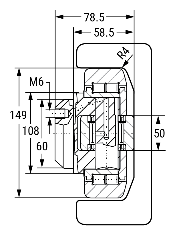
Eccentric Adjustable HVBEA-454
Weight = 0.53 kg
Maximum Bearing Loads:
Radial: Dynamic = 31 kN; Static = 35.5 kN
Axial: Dynamic = 11 kN; Static = 11 kN
Note: Above loads achievable when used with a hardened rail HRC 55 minimum 2.54 mm deep.
Eccentric Adjustable HVBEA-454/HVP0 with Welded Flange plate
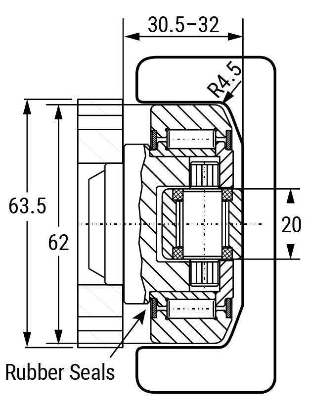
Note: values do not include stack up tolerances for flange plate and bearing assembly.
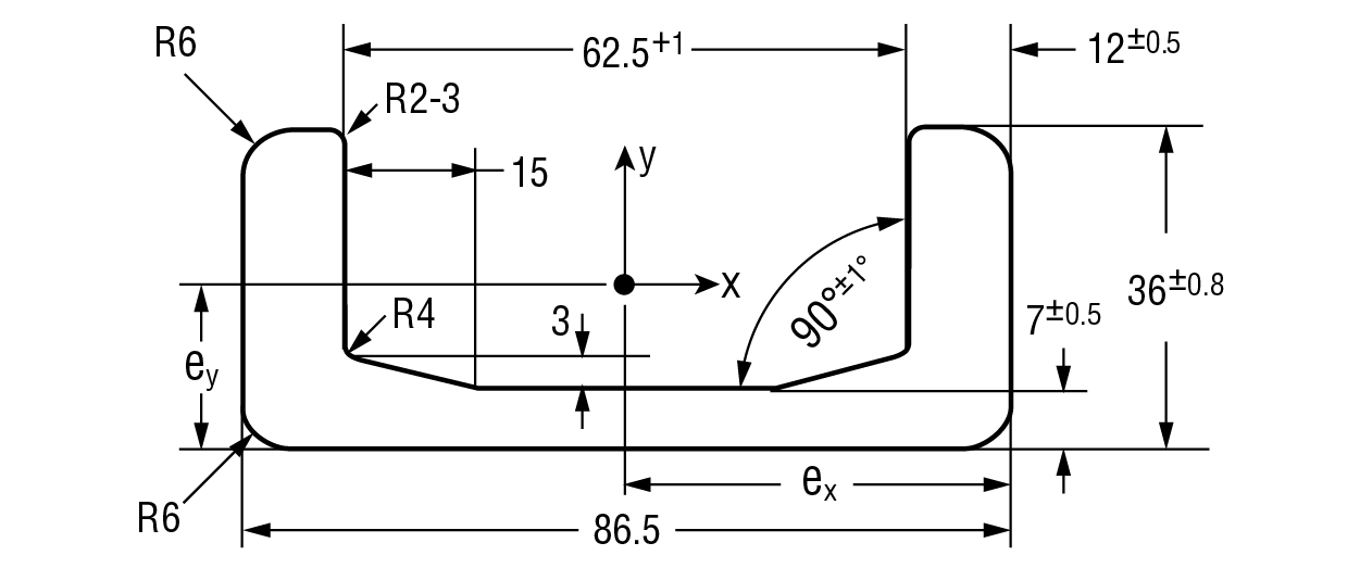
Rail – U Channel HVR-0
Weight = 10.5 kg/m
Moment of Inertia: Ix = 15.35 cm4; Iy = 137.05 cm4
Moment of Resistance: Wx,min = 6.64 cm3; Wx,max = 11.93 cm3; Wy = 31.69 cm3
Radius of Inertia: ix = 1.07 cm; iy = 3.20 cm
Distance to Center of Gravity: ey = 1.29 cm; ex = 4.33 cm
Hevi-Rail Bearings
Can be ordered with pre-welded flange plate

Flange Plate HVP0-1
For ordering separate flange plate only
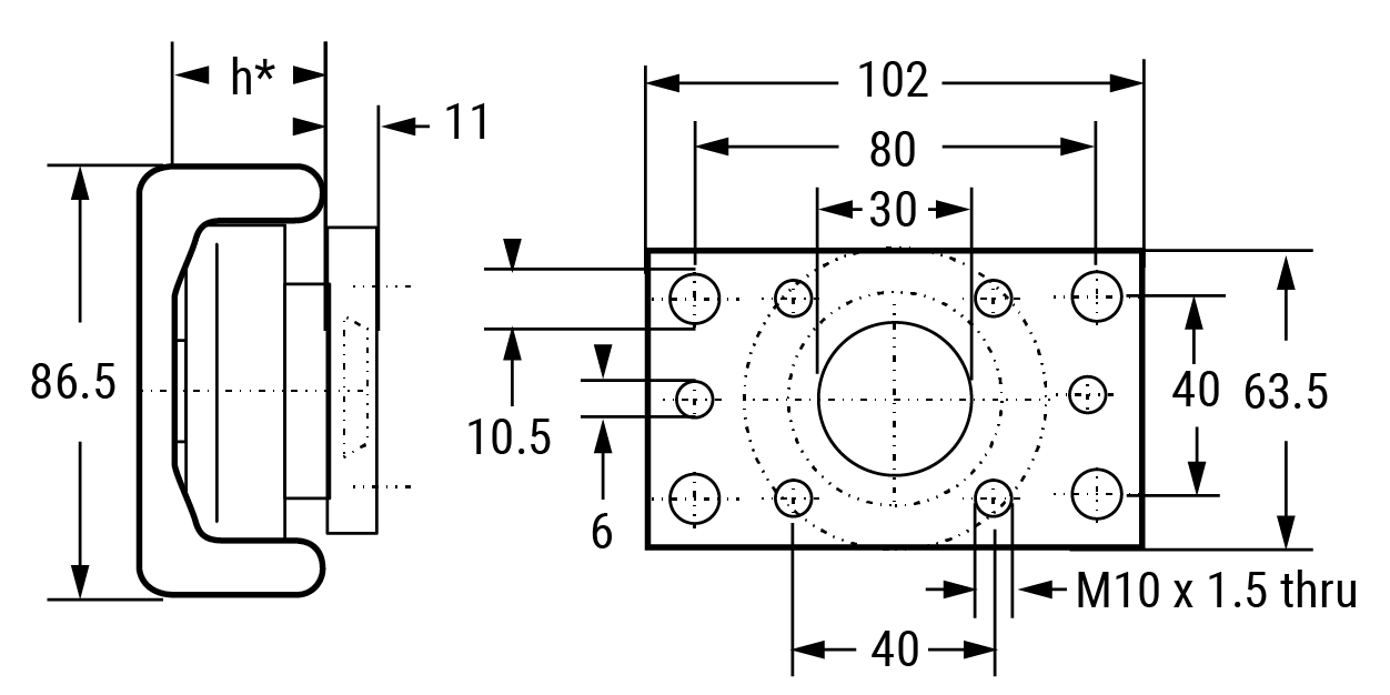
*Note: “h” refers to the depth of the axial bearing. This dimension depends on the choice of fixed axial bearing (HVB-054) or eccentric adjustable bearing (HVBEA-454).
Clamp Flange HVC-0
Ordering Information
| Part No. | Description |
|---|---|
| HVB-054 | Fixed axial bearing |
| HVB-054/HVP0 | Fixed axial bearing with welded flange plate |
| HVBEA-454 | Eccentric adjustable axial bearing |
| HVBEA-454/HVP0 | Eccentric adjustable axial bearing with welded flange plate |
| HVP0-1 | Flange plate |
| HVR-0 | U-channel rail for -54 bearings |
| HVC-0 | Clamp flange |
HVB-055 • 1.39 US Ton-Force
Axial Bearing – Fixed HVB-055
Weight = 0.80 kg
Maximum Bearing Loads:
Radial: Dynamic = 56 kN; Static = 93 kN
Axial: Dynamic = 17 kN; Static = 25 kN
Note: Above loads achievable when used with a hardened rail HRC 58-62 minimum 2.54 mm deep.
Axial Bearing – Fixed HVB 055/HVP1 With Welded Flange Plate
System Maximum Static Loads:
Radial: 12.4 kN/1.39 US Ton-Force
Axial: 3.87 kN/0.43 US Ton-Force
Note: Above loads are achievable when used with shown rails.
Note: values do not include stack up tolerances for flange plate and bearing assembly.
Eccentric Adjustable HVBEA-455
Weight = 0.80 kg
Maximum Bearing Loads:
Radial: Dynamic = 45.5 kN; Static = 51 kN
Axial: Dynamic = 13 kN; Static = 14 kN
Note: Above loads achievable when used with a hardened rail HRC 55 minimum 2.54 mm deep.
Eccentric Adjustable HVBEA-455/HVP1 with welded Flange plate
Note: values do not include stack up tolerances for flange plate and bearing assembly.
Rail – U Channel HVR-1
Weight = 14.8 kg/m
Moment of Inertia: Ix = 27.29 cm4; Iy = 273.50 cm4
Moment of Resistance: Wx,min = 10.91 cm3; Wx,max = 18.20 cm3; Wy = 53.00 cm3
Radius of Inertia: ix = 1.20 cm; iy = 3.81 cm
Distance to Center of Gravity: ey = 1.50 cm; ex = 5.16 cm
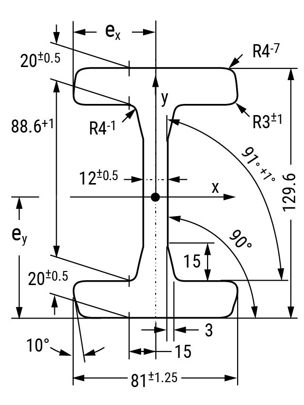
Rail – I Channel HVRI-07
Weight = 19.4 kg/m
Moment of Inertia: Ix = 344.29 cm4; Iy = 57.63 cm4
Moment of Resistance: Wx = 70.26 cm3; Wy = 17.73 cm3
Radius of Inertia: ix = 3.73 cm; iy = 1.52 cm
Distance to Center of Gravity: ey = 4.90 cm; ex = 3.25 cm
Flange Plate HVP1-1
For ordering separate flange plate only
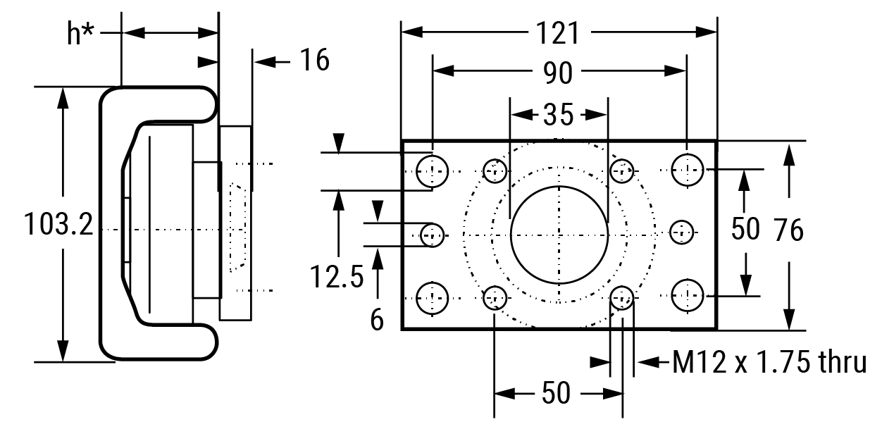
*Note: “h” refers to the depth of the axial bearing. This dimension depends on the choice of fixed axial bearing (HVB-055) or eccentric adjustable bearing (HVBEA-455).
Clamp Flange HVC-1
Ordering Information
| Part No. | Description |
|---|---|
| HVB-055 | Fixed axial bearing |
| HVB-055/HVP1 | Fixed axial bearing with welded flange plate |
| HVBEA-455 | Eccentric adjustable axial bearing |
| HVBEA-455/HVP1 | Eccentric adjustable axial bearing with welded flange plate |
| HVP1-1 | Flange plate |
| HVR-1 | U-channel rail for -55 bearings |
| HVRI-07 | I-channel rail for -55 bearings |
| HVC-1 | Clamp flange |
HVB-056 • 1.45 US Ton-Force
Axial Bearing – Fixed HVB-056
Weight = 1.00 kg
Maximum Bearing Loads:
Radial: Dynamic = 48 kN; Static = 60.8 kN
Axial: Dynamic = 16 kN; Static = 18 kN
Note: Above loads achievable when used with a hardened rail HRC 55 minimum 2.54 mm deep.
Axial Bearing – Fixed HVB 056/HVP2 With Welded Flange Plate
System Maximum Static Loads:
Radial: 12.9 kN/1.45 US Ton-Force
Axial: 4.0 kN/0.44 US Ton-Force
Note: Above loads are achievable when used with shown rails.
Note: values do not include stack up tolerances for flange plate and bearing assembly.
Eccentric Adjustable HVBEA-456
Weight = 1.00 kg
Maximum Bearing Loads:
Radial: Dynamic = 48 kN; Static = 56.8 kN
Axial: Dynamic = 18 kN; Static = 18 kN
Note: Above loads achievable when used with a hardened rail HRC 55 minimum 2.54 mm deep.
Eccentric Adjustable HVBEA-456/HVP2 with Welded Flange plate
Note: values do not include stack up tolerances for flange plate and bearing assembly.
Rail – U Channel HVR-2
Weight = 20.9 kg/m
Moment of Inertia: Ix = 37.92 cm4; Iy = 493.58 cm4
Moment of Resistance: Wx,min = 14.83 cm3; Wx,max = 24.58 cm3; Wy = 81.38 cm3
Radius of Inertia: ix = 1.19 cm; iy = 4.30 cm
Distance to Center of Gravity: ey = 1.54 cm; ex = 6.07 cm
Hevi-Rail Bearings
Can be ordered with pre-welded flange plate
Flange Plate HVP2-1
For ordering separate flange plate only
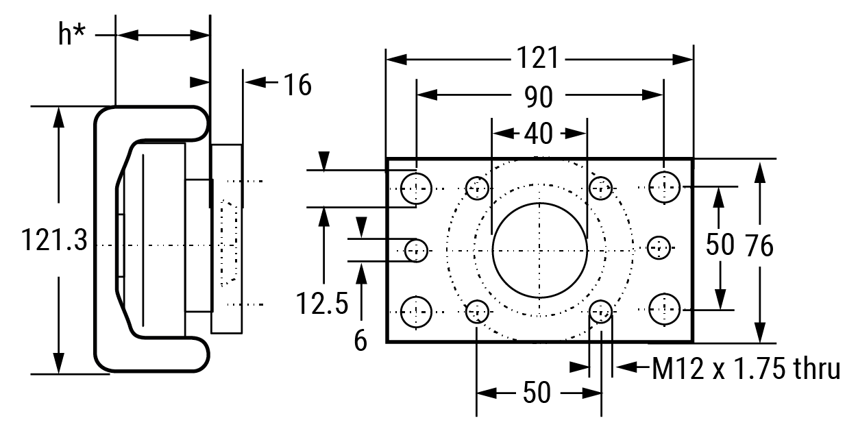
*Note: “h” refers to the depth of the axial bearing. This dimension depends on the choice of fixed axial bearing (HVB-056) or eccentric adjustable bearing (HVBEA-456).
Clamp Flange HVC-2
Ordering Information
| Part No. | Description |
|---|---|
| HVB-056 | Fixed axial bearing |
| HVB-056/HVP2 | Fixed axial bearing with welded flange plate |
| HVBEA-456 | Eccentric adjustable axial bearing |
| HVBEA-456/HVP2 | Eccentric adjustable axial bearing with welded flange plate |
| HVP2-1 | Flange plate |
| HVR-2 | U-channel rail for -56 bearings |
| HVC-2 | Clamp flange |
HVB-057 • 1.45 US Ton-Force
Axial Bearing – Fixed HVB-057
Weight = 0.90 kg
Maximum Bearing Loads:
Radial: Dynamic = 58 kN; Static = 102 kN
Axial: Dynamic = 21 kN; Static = 32 kN
Note: Above loads achievable when used with a hardened rail HRC 55 minimum 2.54 mm deep.
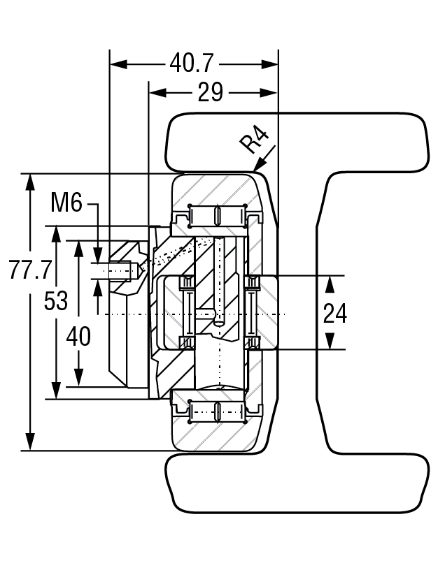
Axial Bearing – Fixed HVB 057/HVP2 With Welded Flange Plate
System Maximum Static Loads:
Radial: 12.9 kN/1.45 US Ton-Force
Axial: 4.0 kN/0.44 US Ton-Force
Note: Above loads are achievable when used with shown rails.
Note: values do not include stack up tolerances for flange plate and bearing assembly.
Eccentric Adjustable HVBEA-457
Weight = 0.87 kg
Maximum Bearing Loads:
Radial: Dynamic = 48 kN; Static = 56.8 kN
Axial: Dynamic = 18 kN; Static = 18 kN
Note: Above loads achievable when used with a hardened rail HRC 55 minimum 2.54 mm deep.
Eccentric Adjustable HVBEA-457/HVP2 with Welded Flange plate
Note: values do not include stack up tolerances for flange plate and bearing assembly.
Rail – I Channel HVRI-08
Weight = 25.3 kg/m
Moment of Inertia: Ix = 597.54 cm4; Iy = 76.79 cm4
Moment of Resistance: Wx = 104.92 cm3; Wy = 23.27 cm3
Radius of Inertia: ix = 4.24 cm; iy = 1.54 cm
Distance to Center of Gravity: ey = 5.70 cm; ex = 3.30 cm
Hevi-Rail Bearings
Can be ordered with pre-welded flange plate
Flange Plate HVP2-1
For ordering separate flange plate only
*Note: “h” refers to the depth of the axial bearing. This dimension depends on the choice of fixed axial bearing (HVB-057) or eccentric adjustable bearing (HVBEA-457).
Ordering Information
| Part No. | Description |
|---|---|
| HVB-057 | Fixed axial bearing |
| HVB-057/HVP2 | Fixed axial bearing with welded flange plate |
| HVBEA-457 | Eccentric adjustable axial bearing |
| HVBEA-457/HVP2 | Eccentric adjustable axial bearing with welded flange plate |
| HVP2-1 | Flange plate |
| HVRI-08 | I-channel rail for -57 bearings |
HVB-058 • 2.51 US Ton-Force
Axial Bearing – Fixed HVB-058
Weight = 1.62 kg
Maximum Bearing Loads:
Radial: Dynamic = 60 kN; Static = 72 kN
Axial: Dynamic = 23 kN; Static = 40 kN
Note: Above loads achievable when used with a hardened rail HRC 55 minimum 2.54 mm deep.

Axial Bearing – Fixed HVB 058/HVP3 With Welded Flange Plate
System Maximum Static Loads:
Radial: 22.4 kN / 2.51 US Ton-Force
Axial: 7.0 kN / 0.78 US Ton-Force
Note: Above loads are achievable when used with shown rails.
Note: values do not include stack up tolerances for flange plate and bearing assembly.
Eccentric Adjustable HVBEA-458
Weight = 1.62 kg
Maximum Bearing Loads:
Radial: Dynamic = 68 kN; Static = 72 kN
Axial: Dynamic = 23 kN; Static = 23 kN
Note: Above loads achievable when used with a hardened rail HRC 55 minimum 2.54 mm deep.
Eccentric Adjustable HVBEA-458/HVP3 with Welded Flange plate
Note: values do not include stack up tolerances for flange plate and bearing assembly.
Rail – U Channel HVR-3
Weight = 28.6 kg/m
Moment of Inertia: Ix = 89.47 cm4; Iy = 865.23 cm4
Moment of Resistance: Wx,min = 27.03 cm3; Wx,max = 44.96 cm3; Wy = 127.80 cm3
Radius of Inertia: ix = 1.57 cm; iy = 4.87 cm
Distance to Center of Gravity: ey = 1.99 cm; ex = 6.77 cm
Rail – I Channel HVRI-09
Weight = 34.1 kg/m
Moment of Inertia: Ix = 1037.22 cm4; Iy = 161.89 cm4
Moment of Resistance: Wx = 160.07 cm3; Wy = 39.97 cm3
Radius of Inertia: ix = 4.89 cm; iy = 1.93 cm
Distance to Center of Gravity: ey = 6.48 cm; ex = 4.05 cm
Flange Plate HVP3-1
For ordering separate flange plate only
*Note: “h” refers to the depth of the axial bearing. This dimension depends on the choice of fixed axial bearing (HVB-058) or eccentric adjustable bearing (HVBEA-458).
Clamp Flange HVC-3

Ordering Information
| Part No. | Description |
|---|---|
| HVB-058 | Fixed axial bearing |
| HVB-058/HVP3 | Fixed axial bearing with welded flange plate |
| HVBEA-458 | Eccentric adjustable axial bearing |
| HVBEA-458/HVP3 | Eccentric adjustable axial bearing with welded flange plate |
| HVP3-1 | Flange plate |
| HVR-3 | U-channel rail for -58 bearings |
| HVRI-09 | I-channel rail for -58 bearings |
| HVC-3 | Clamp flange |
HVB-059 • 2.47 US Ton-Force
Axial Bearing – Fixed HVB-059
Weight = 1.80 kg
Maximum Bearing Loads:
Radial: Dynamic = 73 kN; Static = 82 kN
Axial: Dynamic = 25 kN; Static = 27 kN
Note: Above loads achievable when used with a hardened rail HRC 55 minimum 2.54 mm deep.
Eccentric Adjustable HVBEA-459
Weight = 1.74 kg
Maximum Bearing Loads:
Radial: Dynamic = 73 kN; Static = 82 kN
Axial: Dynamic = 25 kN; Static = 27 kN
Note: Above loads achievable when used with a hardened rail HRC 55 minimum 2.54 mm deep.
Rail – I Channel HVRI-10
Weight = 30.9 kg/m
Moment of Inertia: Ix = 1078.01 cm4; Iy = 104.38 cm4
Moment of Resistance: Wx = 154.33 cm3; Wy = 29.89 cm3
Distance to Center of Gravity: ey = 6.99 cm; ex = 3.49 cm
System Maximum Static Loads:
Radial: 22 kN / 2.47 US Ton-Force
Axial: 7.0 kN / 0.78 US Ton-Force
Note: Above loads are achievable when used with shown rails.
Ordering Information
| Part No. | Description |
|---|---|
| HVB-059 | Fixed axial bearing |
| HVBEA-459 | Eccentric adjustable axial bearing |
| HVRI-10 | I-channel profile rail |
HVB-060 • 2.67 US Ton-Force
Axial Bearing – Fixed HVB-060
Weight = 2.30 kg
Maximum Bearing Loads:
Radial: Dynamic = 81 kN; Static = 95 kN
Axial: Dynamic = 31 kN; Static = 36 kN
Note: Above loads achievable when used with a hardened rail HRC 55 minimum 2.54 mm deep.
Eccentric Adjustable HVBEA-460
Weight = 2.27 kg
Maximum Bearing Loads:
Radial: Dynamic = 81 kN; Static = 95 kN
Axial: Dynamic = 31 kN; Static = 36 kN
Note: Above loads achievable when used with a hardened rail HRC 55 minimum 2.54 mm deep.
Rail – I Channel HVRI-11
Weight = 40.5 kg/m
Moment of Inertia: Ix = 1670.08 cm4; Iy = 184.52 cm4
Moment of Resistance: Wx = 219.17 cm3; Wy = 44.46 cm3
Radius of Inertia: ix = 5.69 cm; iy = 1.91 cm
Distance to Center of Gravity: ey = 7.62 cm; ex = 4.15 cm
System Maximum Static Loads:
Radial: 23.8 kN / 2.67 US Ton-Force
Axial: 7.44 kN / 0.83 US Ton-Force
Note: Above loads are achievable when used with shown rails.
Ordering Information
| Part No. | Description |
|---|---|
| HVB-060 | Fixed axial bearing |
| HVBEA-460 | Eccentric adjustable axial bearing |
| HVRI-11 | I-channel profile rail |
HVB-061 • 2.67 US Ton-Force
Axial Bearing – Fixed HVB-061
Weight = 2.82 kg
Maximum Bearing Loads:
Radial: Dynamic = 81 kN; Static = 95 kN
Axial: Dynamic = 31 kN; Static = 36 kN
Note: Above loads achievable when used with a hardened rail HRC 55 minimum 2.54 mm deep.
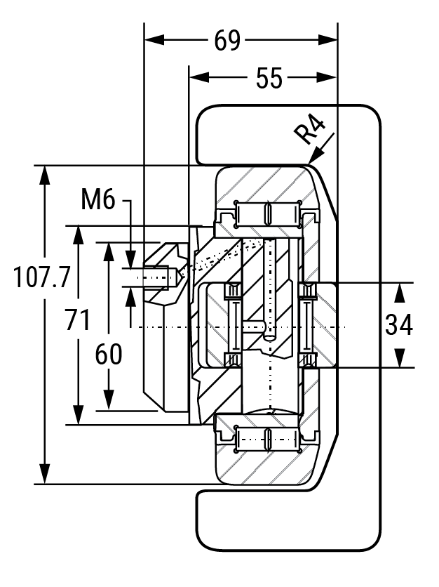
Axial Bearing – Fixed HVB-061/HVP4 with Welded Flange Plate
System Maximum Static Loads:
Radial: 23.8 kN / 2.67 US Ton-Force
Axial: 7.44 kN / 0.83 US Ton-Force
Note: Above loads are achievable when used with shown rails.
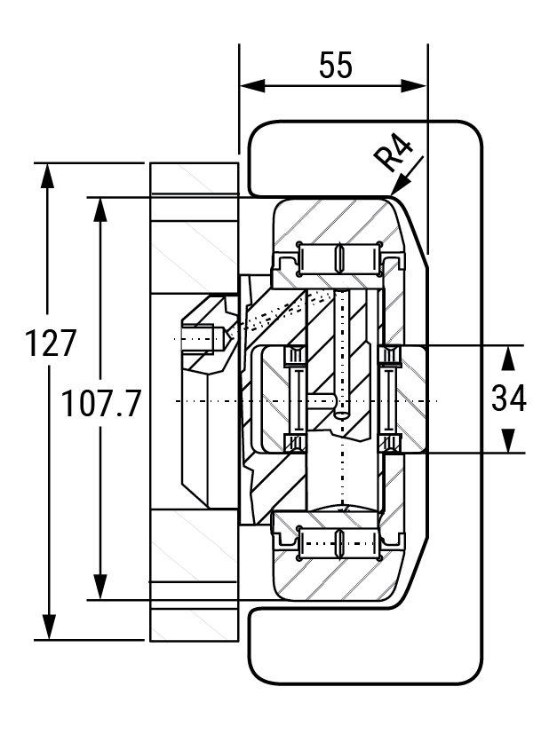
Note: values do not include stack up tolerances for flange plate and bearing assembly.
Eccentric Adjustable HVBEA-461
Weight = 2.82 kg
Maximum Bearing Loads:
Radial: Dynamic = 81 kN; Static = 95 kN
Axial: Dynamic = 31 kN; Static = 36 kN
Note: Above loads achievable when used with a hardened rail HRC 55 minimum 2.54 mm deep.
Eccentric Adjustable HVBEA-461/HVP4 with Welded Flange plate
Note: values do not include stack up tolerances for flange plate and bearing assembly.
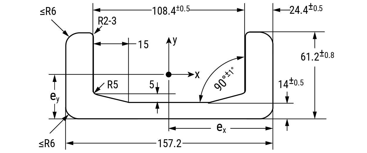
Rail – U Channel HVR-4
Weight = 35.9 kg/m
Moment of Inertia: Ix = 150.98 cm4; Iy = 1494.32 cm4
Moment of Resistance: Wx,min = 39.00 cm3; Wx,max = 67.13 cm3; Wy = 190.12 cm3
Radius of Inertia: ix = 1.82 cm; iy = 5.72 cm
Distance to Center of Gravity: ey = 2.25 cm; ex = 7.86 cm
Hevi-Rail Bearings
Can be ordered with pre-welded flange plate

Flange Plate HVP4-1
For ordering separate flange plate only
*Note: “h” refers to the depth of the axial bearing. This dimension depends on the choice of fixed axial bearing (HVB-061) or eccentric adjustable bearing (HVBEA-461).
Clamp Flange HVC-4
Ordering Information
| Part No. | Description |
|---|---|
| HVB-061 | Fixed axial bearing |
| HVB-061/HVP4 | Fixed axial bearing with welded flange plate |
| HVBEA-461 | Eccentric adjustable axial bearing |
| HVBEA-461/HVP4 | Eccentric adjustable axial bearing with welded flange plate |
| HVP4-1 | Flange plate |
| HVR-4 | U-channel rail for -61 bearings |
| HVC-4 | Clamp flange |
HVB-062 • 3.81 US Ton-Force
Axial Bearing – Fixed HVB-062
Weight = 4.50 kg
Maximum Bearing Loads:
Radial: Dynamic = 134.5 kN; Static = 242 kN
Axial: Dynamic = 44.7 kN; Static = 74.2 kN
Note: Above loads achievable when used with a hardened rail HRC 55 minimum 2.54 mm deep.
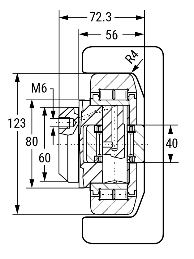
Axial Bearing – Fixed HVB-062/HVP4 With Welded Flange Plate
System Maximum Static Loads:
Radial: 33.9 kN / 3.81 US Ton-Force
Axial: 10.6 kN / 1.19 US Ton-Force
Note: Above loads are achievable when used with shown rails.
Note: values do not include stack up tolerances for flange plate and bearing assembly.
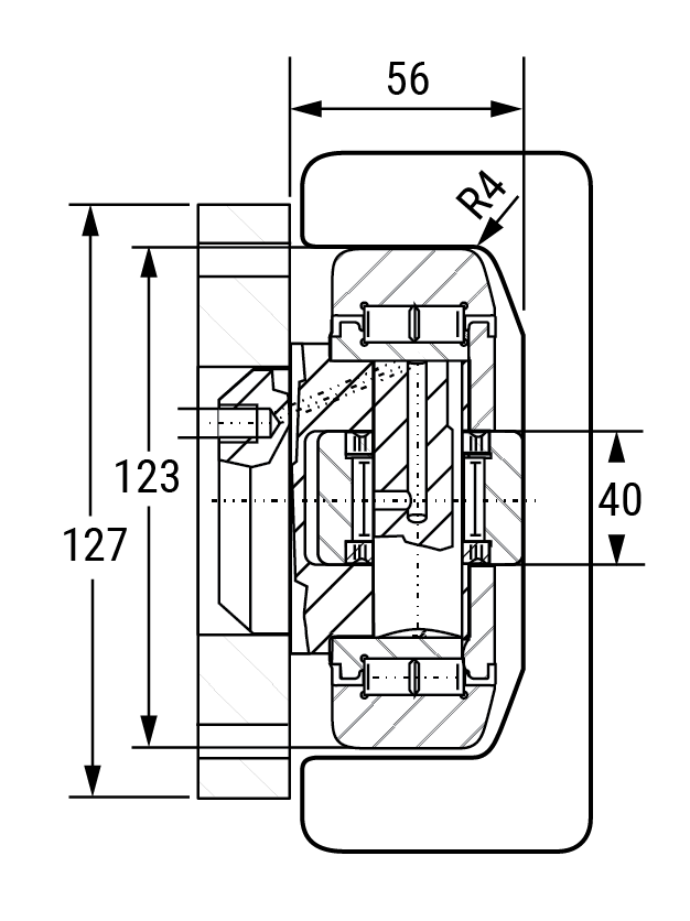
Eccentric Adjustable HVBEA-462
Weight = 3.90 kg
Maximum Bearing Loads:
Radial: Dynamic = 110 kN; Static = 132 kN
Axial: Dynamic = 43 kN; Static = 50 kN
Note: Above loads achievable when used with a hardened rail HRC 55 minimum 2.54 mm deep.
Eccentric Adjustable HVBEA-462/HVP4 with Welded Flange plate
Note: values do not include stack up tolerances for flange plate and bearing assembly.
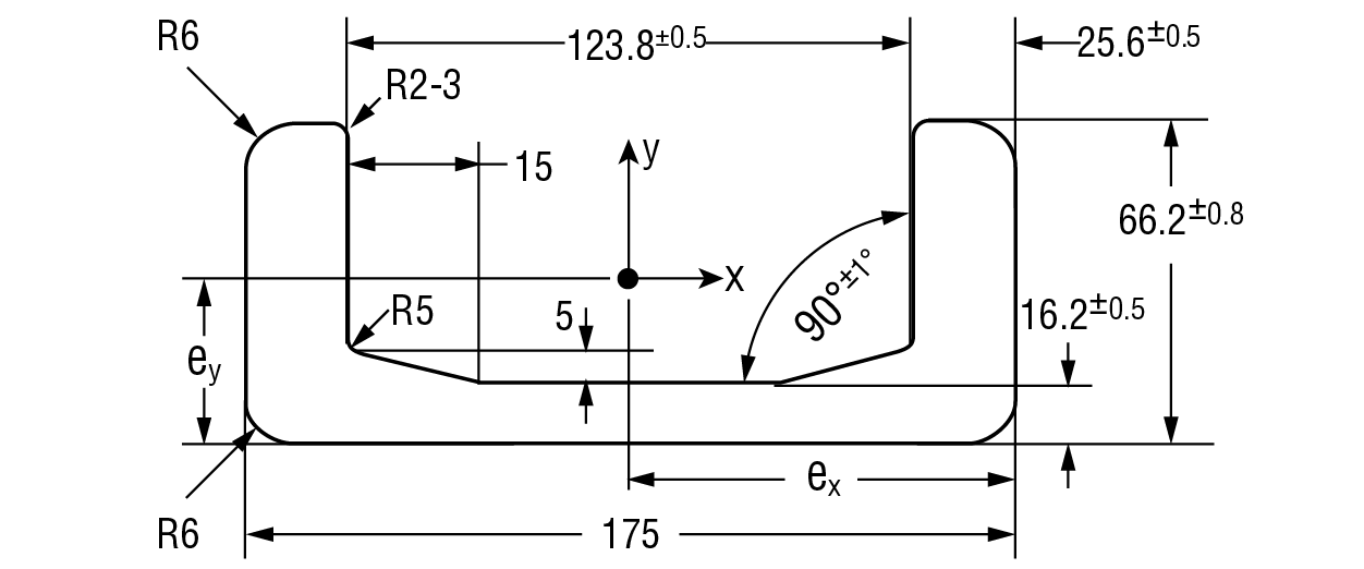
Rail – U Channel HVR-5
Weight = 42.9 kg/m
Moment of Inertia: Ix = 205.84 cm4; Iy = 2185.32 cm4
Moment of Resistance: Wx,min = 48.42 cm3; Wx,max = 86.89 cm3; Wy = 249.75 cm3
Radius of Inertia: ix = 1.94 cm; iy = 6.32 cm
Distance to Center of Gravity: ey = 2.37 cm; ex = 8.75 cm
Hevi-Rail Bearings
Can be ordered with pre-welded flange plate

Flange Plate HVP4-1
For ordering separate flange plate only

*Note: “h” refers to the depth of the axial bearing. This dimension depends on the choice of fixed axial bearing (HVB-062) or eccentric adjustable bearing (HVBEA-462).
Ordering Information
| Part No. | Description |
|---|---|
| HVB-062 | Fixed axial bearing |
| HVB-062/HVP4 | Fixed axial bearing with welded flange plate |
| HVBEA-462 | Eccentric adjustable axial bearing |
| HVBEA-462/HVP4 | Eccentric adjustable axial bearing with welded flange plate |
| HVP4-1 | Flange plate |
| HVR-5 | U-channel rail for -62 bearings |
HVB-063 • 6.65 US Ton-Force
Axial Bearing – Fixed HVB-063
Weight = 6.52 kg
Maximum Bearing Loads:
Radial: Dynamic = 188 kN; Static = 370 kN
Axial: Dynamic = 68 kN; Static = 71 kN
Note: Above loads achievable when used with a hardened rail HRC 55 minimum 2.54 mm deep.
Axial Bearing – Fixed HVB-063/HVP6 With Welded Flange Plate
System Maximum Static Loads:
Radial: 59.2 kN / 6.65 US Ton-Force
Axial: 18.5 kN / 2.07 US Ton-Force
Note: Above loads are achievable when used with shown rails.
Note: values do not include stack up tolerances for flange plate and bearing assembly.
Eccentric Adjustable HVBEA-463
Weight = 6.50 kg
Maximum Bearing Loads:
Radial: Dynamic = 151 kN; Static = 192 kN
Axial: Dynamic = 68 kN; Static = 71 kN
Note: Above loads achievable when used with a hardened rail HRC 55 minimum 2.54 mm deep.
Eccentric Adjustable HVBEA-463/HVP6 with Welded Flange plate
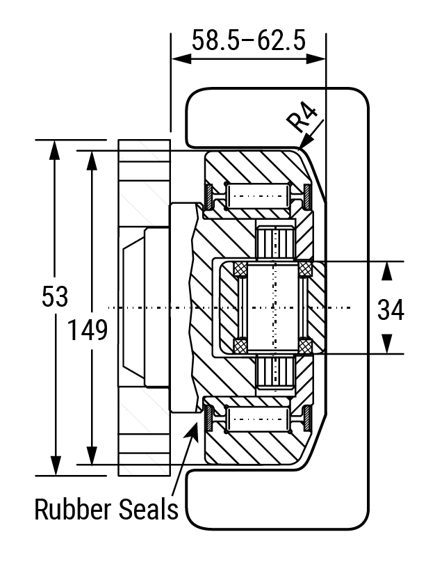
Note: values do not include stack up tolerances for flange plate and bearing assembly.
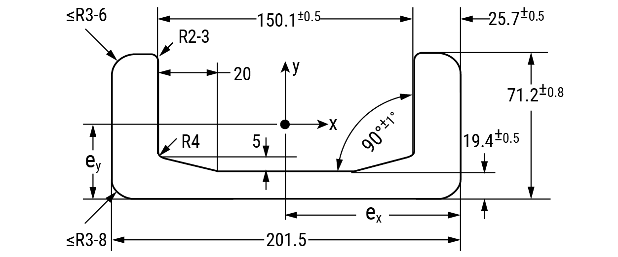
Rail – U Channel HVR-6
Weight = 52.3 kg/m
Moment of Inertia: Ix = 269.52 cm4; Iy = 3423.08 cm4
Moment of Resistance: Wx,min = 57.15 cm3; Wx,max = 112.11 cm3; Wy = 339.76 cm3
Radius of Inertia: ix = 2.01 cm; iy = 7.17 cm
Distance to Center of Gravity: ey = 2.40 cm; ex = 10.08 cm
Hevi-Rail Bearings
Can be ordered with pre-welded flange plate

Flange Plate HVP6-1
For ordering separate flange plate only
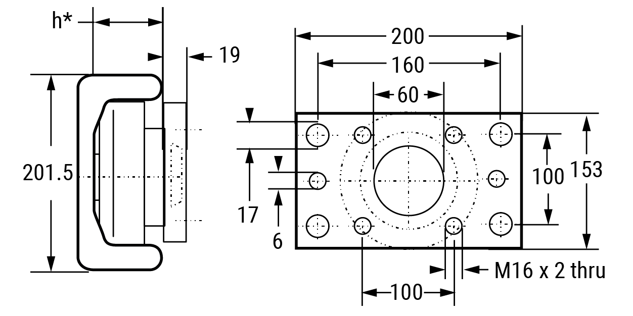
*Note: “h” refers to the depth of the axial bearing. This dimension depends on the choice of fixed axial bearing (HVB-063) or eccentric adjustable bearing (HVBEA-463).
Ordering Information
| Part No. | Description |
|---|---|
| HVB-063 | Fixed axial bearing |
| HVB-063/HVP6 | Fixed axial bearing with welded flange plate |
| HVBEA-463 | Eccentric adjustable axial bearing |
| HVBEA-463/HVP6 | Eccentric adjustable axial bearing with welded flange plate |
| HVP6-1 | Flange plate |
| HVR-6 | U-channel rail for -63 bearings |
Technical • Static Loading Calculations
The load applied to a linear system can vary in many ways. Factors such as the center of gravity, drive or thrust location, forces of inertia at start and stop, need to be calculated to ensure the proper rail, and carriage are applied.
Horizontal Motion – Single Rail
Load on the sliders:
\( P_1 = P_2 + F \qquad P_2 = F \cdot \frac{a}{b} \)

Horizontal Motion – Single Rail
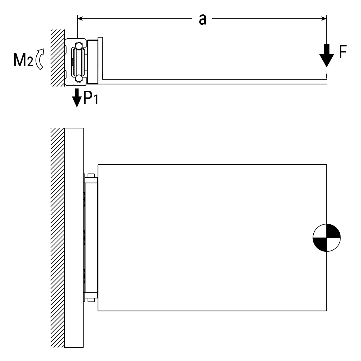
\( P_1 = F \qquad M_2 = F \cdot a \)
Vertical Motion – Single Rail

\( P_1 \approx P_2 = F \cdot \frac{a}{b} \)
Horizontal Motion – Single Rail
Verification when change of direction affects inertial forces
Explanation of the calculation formula
F = effective force (N)
Fg = weight-force (N)
P1, P2, P3, P4 = effective load on the slider (N)
M1, M2 = effective moment (N-m)
m = mass (kg)
a = acceleration (m/s2)
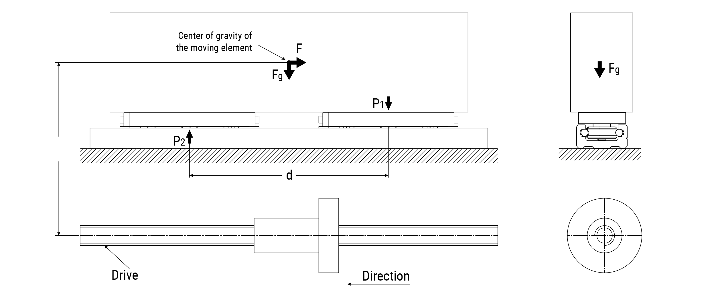
Inertial Force
\( F = m \cdot a \)
Slider Load at time of reverse
\( P_1 = \frac{F \cdot l}{d} + \frac{F_g}{2} \qquad P_2 = \frac{F_g}{2} - \frac{F \cdot l}{d} \)
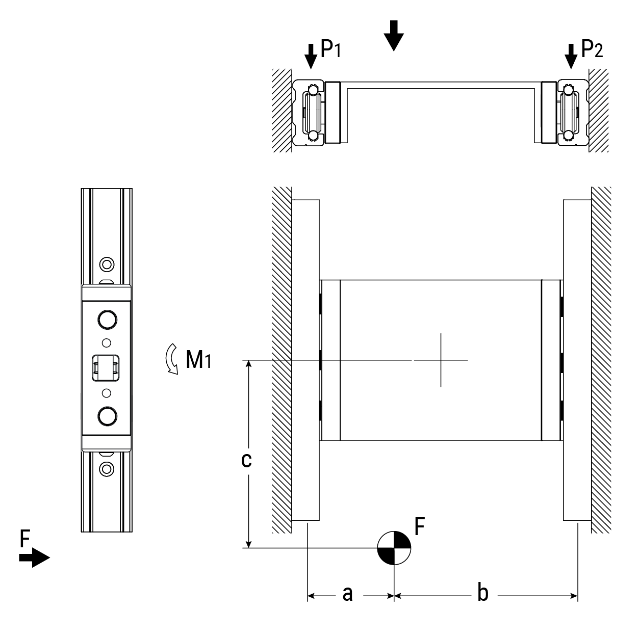
Horizontal Motion – Parallel Rails/2 Carriages
Load on the sliders:
\( P_1 = F \cdot \frac{b}{a + b} \qquad P_2 = F - P_1 \)
Additional moment load on slider:
\( M_1 = \frac{F}{2} \cdot c \)
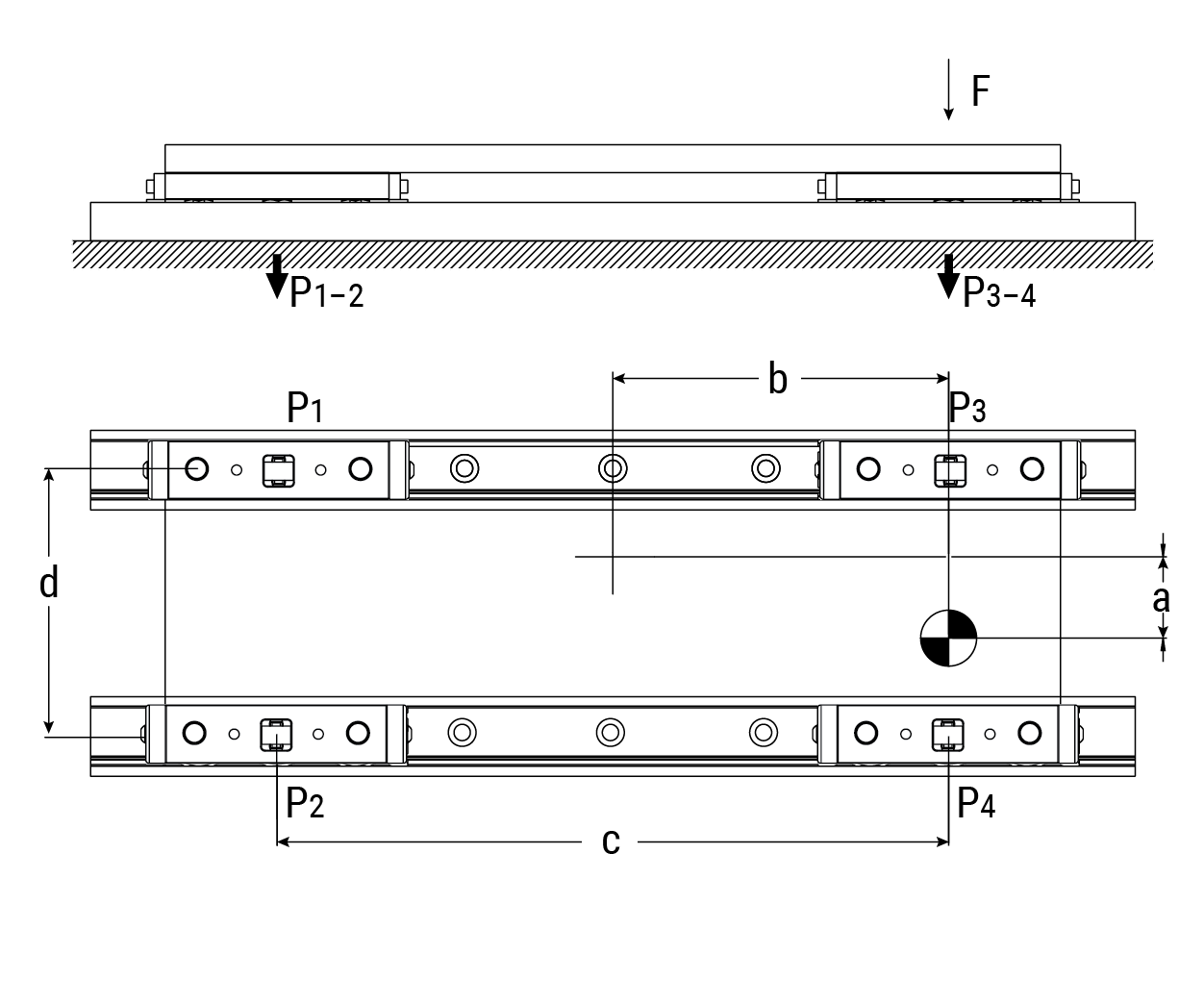
Horizontal Motion – Parallel Rails/4 Carriages
\( P_1 = \frac{F}{4} - \left( \frac{F}{2} \cdot \frac{b}{c} \right) - \left( \frac{F}{2} \cdot \frac{a}{d} \right) \)
\( P_2 = \frac{F}{4} - \left( \frac{F}{2} \cdot \frac{b}{c} \right) + \left( \frac{F}{2} \cdot \frac{a}{d} \right) \)
\( P_3 = \frac{F}{4} + \left( \frac{F}{2} \cdot \frac{b}{c} \right) - \left( \frac{F}{2} \cdot \frac{a}{d} \right) \)
\( P_4 = \frac{F}{4} + \left( \frac{F}{2} \cdot \frac{b}{c} \right) + \left( \frac{F}{2} \cdot \frac{a}{d} \right) \)
Note: Carriage #4 (P4) should always be nearest to the point of the load
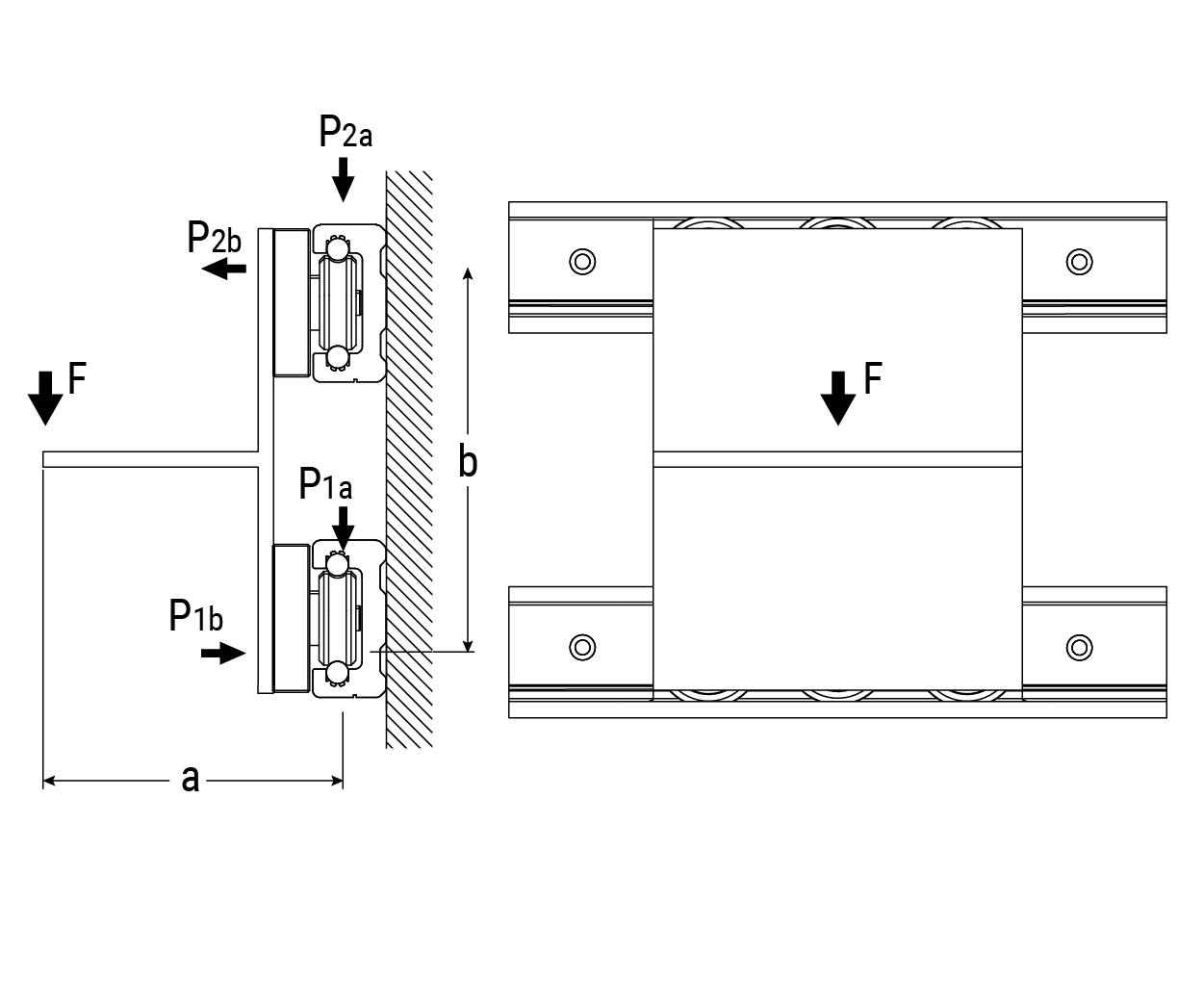
Horizontal Motion – Parallel Rails/2 Carriages
Load on the carriages:
\( P_{1a} = P_{2a} = \frac{F}{2} \)
\( P_{2b} = P_{1b} = F \cdot \frac{a}{b} \)
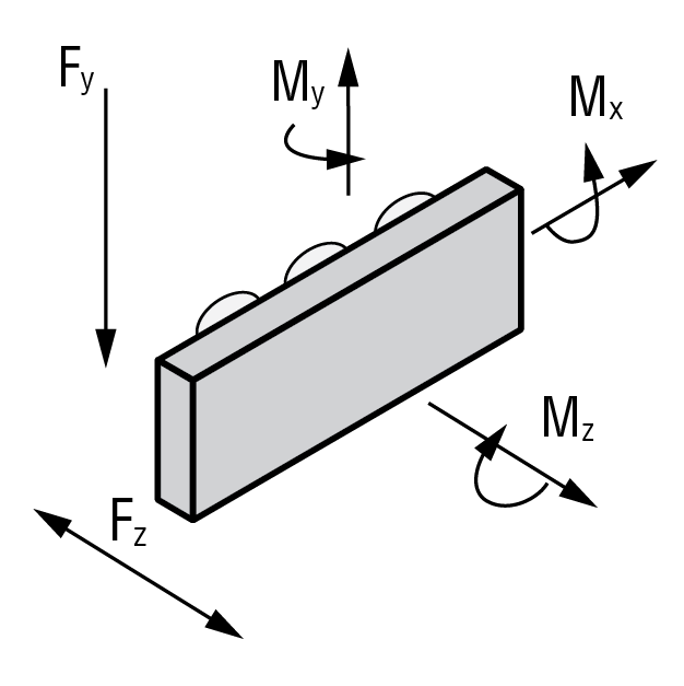
Use the values from the static load maximums given in the charts beginning on page 6 in the calculations below to verify acceptable loading conditions.
Calculation Factors:
- Fza and Fya are the axial and radial results of external forces in newtons (N)
- Mxa, Mya, and Mza are the external moments being applied in newton-meters (N-m)
- Fy, Fz, Mx, My, and Mz are the load ratings for various directions and moments
- s.f. is the relative safety factor as applied from the table below
Single Load Force Calculations
\( \frac{F_{za}}{F_z} < \frac{1}{s.f.} \)
\( \frac{F_{ya}}{F_y} < \frac{1}{s.f.} \)
\( \frac{M_{xa}}{M_x} < \frac{1}{s.f.} \)
\( \frac{M_{ya}}{M_y} < \frac{1}{s.f.} \)
\( \frac{M_{za}}{M_z} < \frac{1}{s.f.} \)
Multiple Load Force Calculation
\( \frac{F_{za}}{F_z} + \frac{F_{ya}}{F_y} + \frac{M_{xa}}{M_x} + \frac{M_{ya}}{M_y} + \frac{M_{za}}{M_z} < \frac{1}{s.f.} \)
Calculation Factors
Use the following variables with the equations below to calculate the approximate travel life of Redi-Rail® carriages under various loading conditions.
- L = Estimated travel life in meters (m)
- Fza and Fya are the axial and radial results of applied external forces in newtons (N)
- Mxa, Mya, and Mza are the external moments being applied in newton-meters (Nm)
- Fd is the dynamic slider capacity constant from the charts beginning on page 6
- Fy, Fz, Mx, My, and Mz are the load ratings for various directions and moments as found beginning on page 6
- s.f. is the relative safety factor from the table below
Weqv is the total radial load found from the equation:
\( W_{eqv} = F_z \cdot \left( \frac{F_{za}}{F_z} + \frac{M_{xa}}{M_x} + \frac{M_{ya}}{M_y} + \frac{M_{za}}{M_z} \right) + F_{ya} \)
Life Calculation:
\( L = \left( \frac{F_d}{W_{eqv} \cdot s.f.} \right)^3 \times 100,000 \text{ meters} \)
Safety Factors
- Use the “s.f.” to adjust for dynamic forces and conditions particular to the application
| Application Condition | S.F. |
|---|---|
| Consistently smooth motion with low frequency of travel reversal, slow speed (<30% MAX), no shock load or vibration, no elastic yield or deformation, clean environment | 1–1.5 |
| Normal assembly or shop floor conditions, moderate speed (30% MAX to 75% MAX), normal shock or vibration conditions | 1.5–2 |
| Frequent reversal of travel, high speeds (>75% MAX), shock loads and/or vibration present, high elastic yield or deformation, heavy dirt and dust in environment | 2–3.5 |
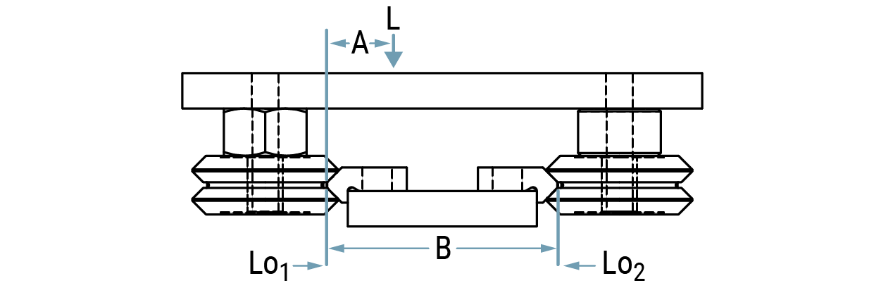
Load Calculations
L = applied load / number of wheel pairs
LR = wheel radial load
LO = wheel load from moment
A = load offset dimension
B = track width dimension
FA = .5 for light duty, well lubricated use
FA = 1 for normal lubricated use
FA = 2 for dry, or harsh environments
Horizontal Motion – Center Loaded
\( L_{O1} = \frac{L \cdot (B - A) \cdot FA}{B} \qquad L_{O2} = (L \cdot FA) - L_{O1} \)
Compare the greater of these loads to the rated moment and radial load capacities.
Example:
Load is 100 lb. on 4 wheel carriage:
L = 100 / 2 pair wheels = 50 lb.
A = 4", B = 10", FA = 1
\( L_{O1} = \frac{50 \cdot (10 - 4)}{10} \cdot 1 = 30 \text{ lb.} \)
\( L_{O2} = 50 - 30 = 20 \text{ lb.} \)
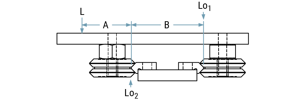
Horizontal Motion – Overhung Load
\( L_{O1} = \frac{L \cdot A \cdot FA}{B} \qquad L_{O2} = (L \cdot FA) + L_{O1} \)
Compare the greater of these loads to the rated moment
and radial load capacities
Example:
Load is 100 lb. on 4 wheel carriage:
L = 100 / 2 pair wheels = 50 lb.
A = 4", B = 6", FA = 1
\( L_{O1} = \frac{50 \cdot 4 \cdot 1}{6} = 33 \text{ lb.} \)
\( L_{O2} = 50 + 33 = 83 \text{ lb.} \)
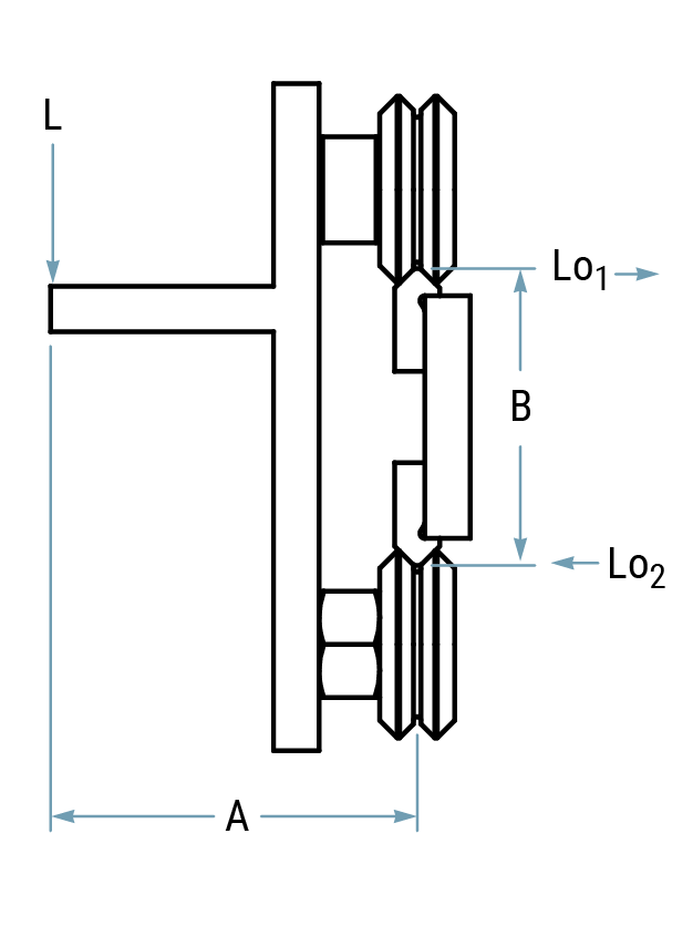
Vertical Motion
\( L_{O1} = \frac{L \cdot A}{B} \cdot FA \qquad L_{R} = (L \cdot FA) + L_{O1} \qquad L_{O1} = L_{O2} \)
Compare the greater of these loads to the rated moment and radial load capacities.
Example:
Load is 100 lb. on 4 wheel carriage:
L = 100 / 2 pair wheels = 50 lb.
A = 4", B = 6", FA = 1
\( L_{O1} = \frac{50 \cdot 4 \cdot 1}{6} = 33 \text{ lb.} \)
\( L_{R} = (50 \cdot 1) + 33 = 83 \text{ lb.} \)
Wheel/Bushing Assembly
Use SAE series N flat washers and lock washers to secure the wheel bushing assemblies
| Bushings | |||
|---|---|---|---|
| Inch | Metric | ||
| VB1 | #6 | MVB1 | M4 |
| VB2 | 1/4 | MVB2 | M6 |
| VB3 | 5/16 | MVB3 | M8 |
| VB4 | 3/8 | MVB4 | M10 |
| V-Rail | |||
|---|---|---|---|
| VR1 | #6, M3 | VR3 | 1/4", M6 |
| VR2 | #10, M6 | VR4 | 5/16”, M8 |
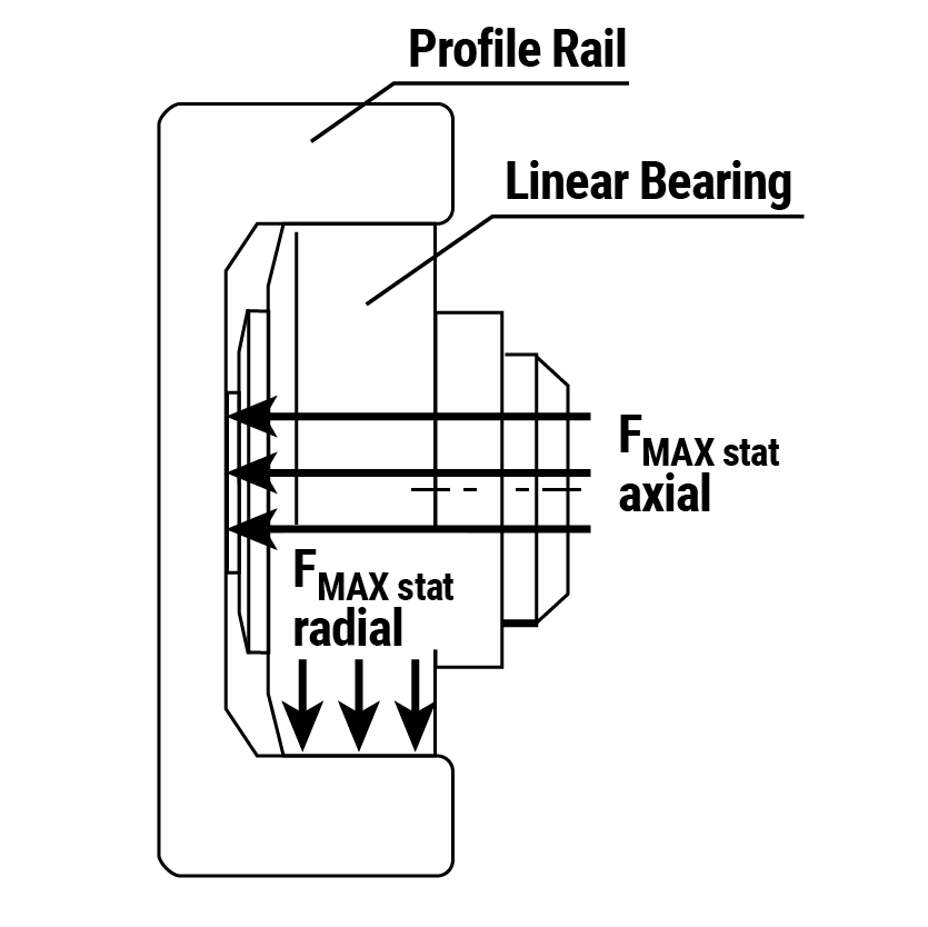
Technical • Specifications & Cantilevered Loads
Technical Specifications
Linear Bearing for Axial & Radial Loads
Prior to welding, disassemble bearing components. To avoid cracks in welded joints, please use welding electrodes and core weld for unalloyed steel.
Outer ring – Case-hardened steel En 31 - SAE 52100 hardened at 60+2 HRc.
Inner ring – Hardened steel En 31 - SAE 52100 hardened at 62-2 HRc.
Cylindrical rollers – Flat ground heads are hardened steel, En 31 - SAE 52100, hardened at 59-64 HRC.
Bolt tolerance – 0.05 mm:
Profile rails – High quality S450J2 MOD. steel at standard lengths of 6 m (19.7 ft). Yield point of 420 n/mm², tensile strength of 550-700 N/mm2. Rails are not hardened but have a Brinell hardness of 150-190. The guide ways in the rails should be lightly greased and not painted.
Clamp flange – Low carbon steel, adjustable clamp.
Flange plate – Low carbon steel. Special designs available, contact manufacturer.
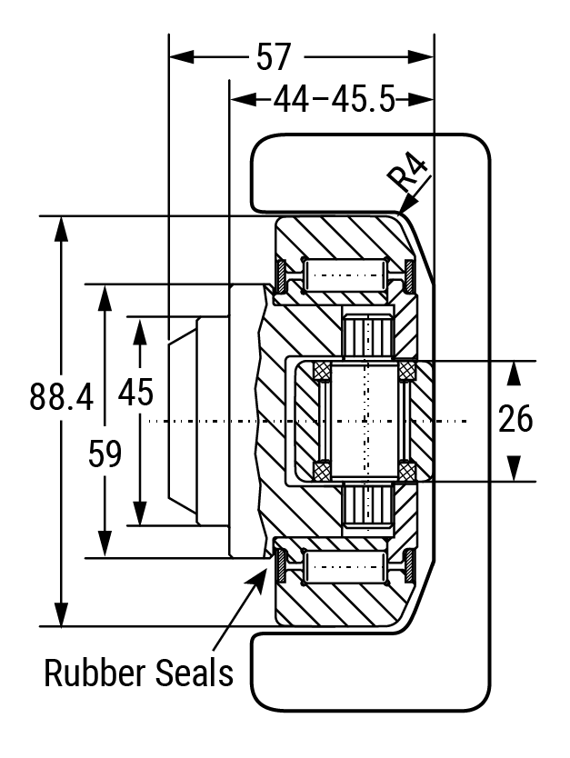
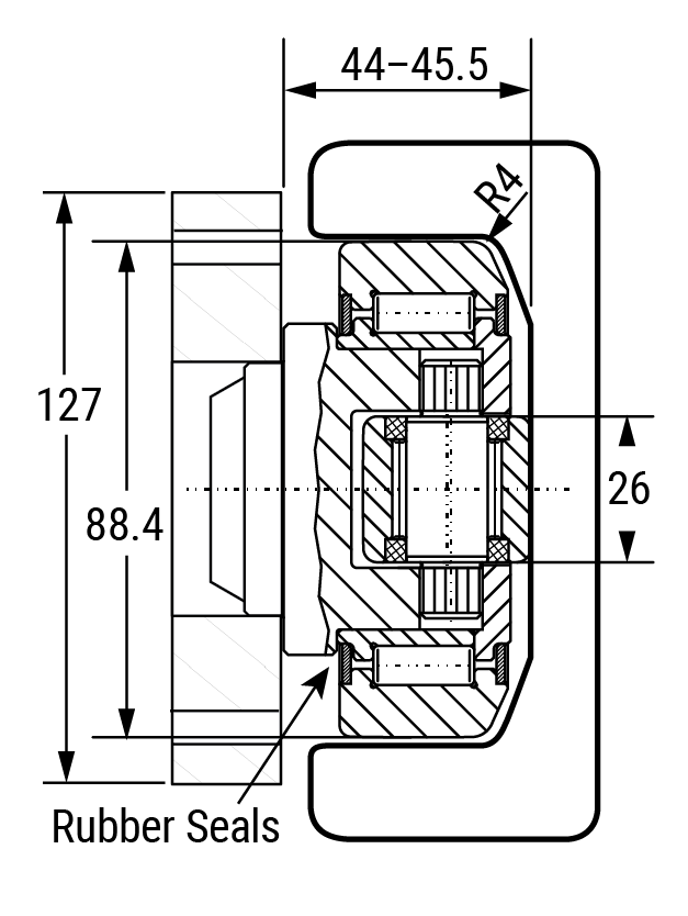
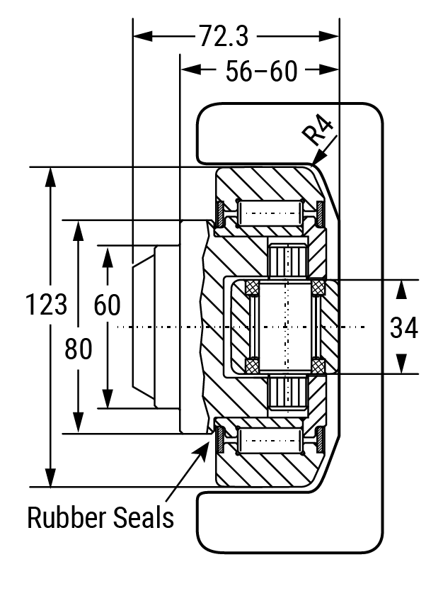
Seals – Fixed Axial Bearings (HVB-053 to HVB-063): Radial roller has steel labyrinth and axial roller has rubber seals.
Eccentric Adjustable Axial Bearings (HVBEA-454 to HVBEA-463) Both radial roller and axial roller have rubber seals. Rubber seals are RS type.
Lubrication – Bearings are supplied lubricated with grease grade 3. Bearings from HVB-055 to HVB-063 can be re-lubricated with grease zerk. Adjustable bearings are not available with zerk.
Bearing coefficient of frictions – 0.010 static, 0.005 dynamic.
Temperature – Resistant from -30°C to 120°C (-22°F to 248°F).
Bearing Life Calculations:
L10 = \( \frac{16,667}{n} \cdot \left( \frac{C}{P} \right)^{10/3} \cdot \text{(Hours)} \)
C = Dynamic load rating (kN)
P = Automatic dynamic load (kN)
n = Revolutions per minute (rpm)
Note: Above calculation formula is for predicting life expectance with 90% reliability level. Customers shall use their discretion to determine the reduction factor based on the actual operation needs and conditions such as reliability level, load, speed, impact, and environments.
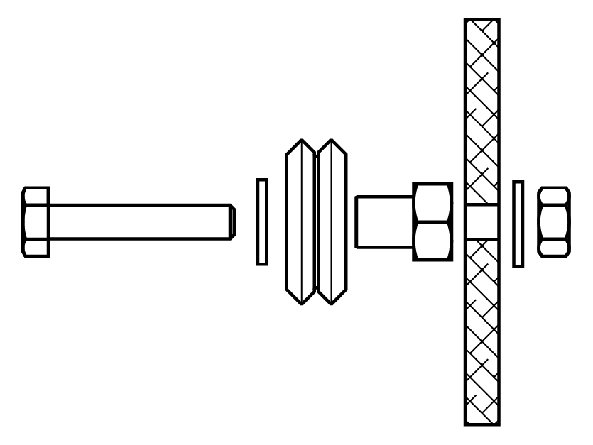
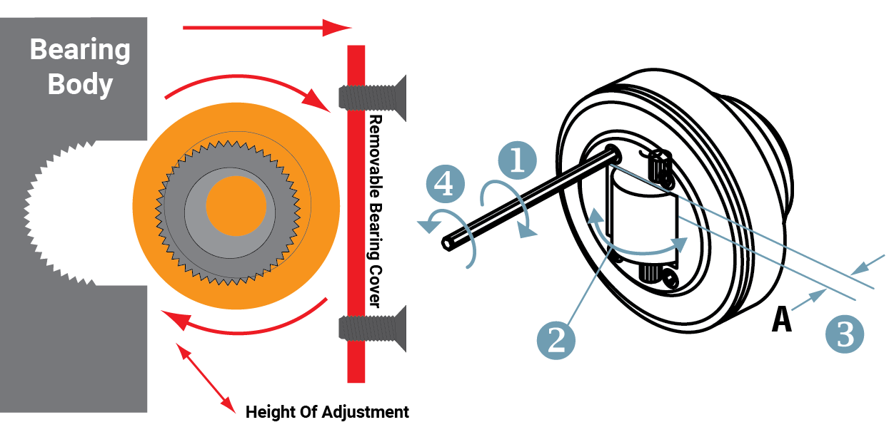
Adjusting Axial Bearings
- Remove front screws
- Rotate axial bearing shaft
(see diagram below) - Check dimension A
(repeat step 2, if needed) - Re-install front screws
- Recommend use of a breakable Loctite®
Calculation of fmax for cantilevered loads
Q = Load capacity (N)
L = Load distance to suspension point (mm)
P = Suspension point
A = Bearing distance (mm) recommended 500 mm to 1,000 mm
Formula: \( F_{\text{MAX stat radial}} \, [\text{N}] = \frac{Q \cdot L}{2 \cdot A} \)
MAX Hertzian = 850 N/mm² for all profile rails Indicated here are \( F_{\text{MAX stat radial}} \) + axial for each bearing
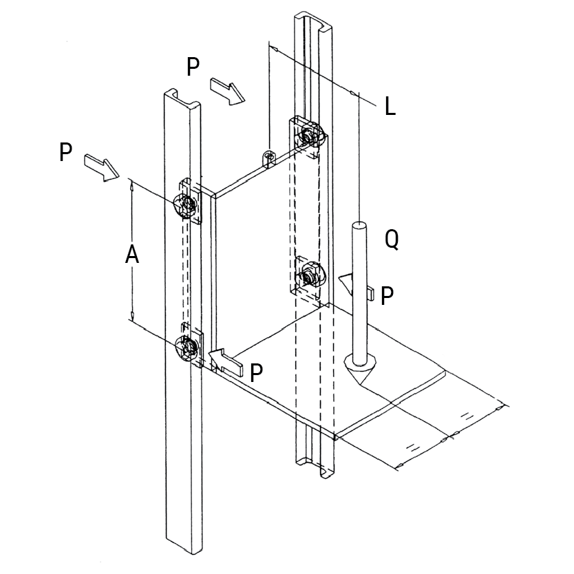
Technical • Mounting
Mounting Configurations
Lifting Units
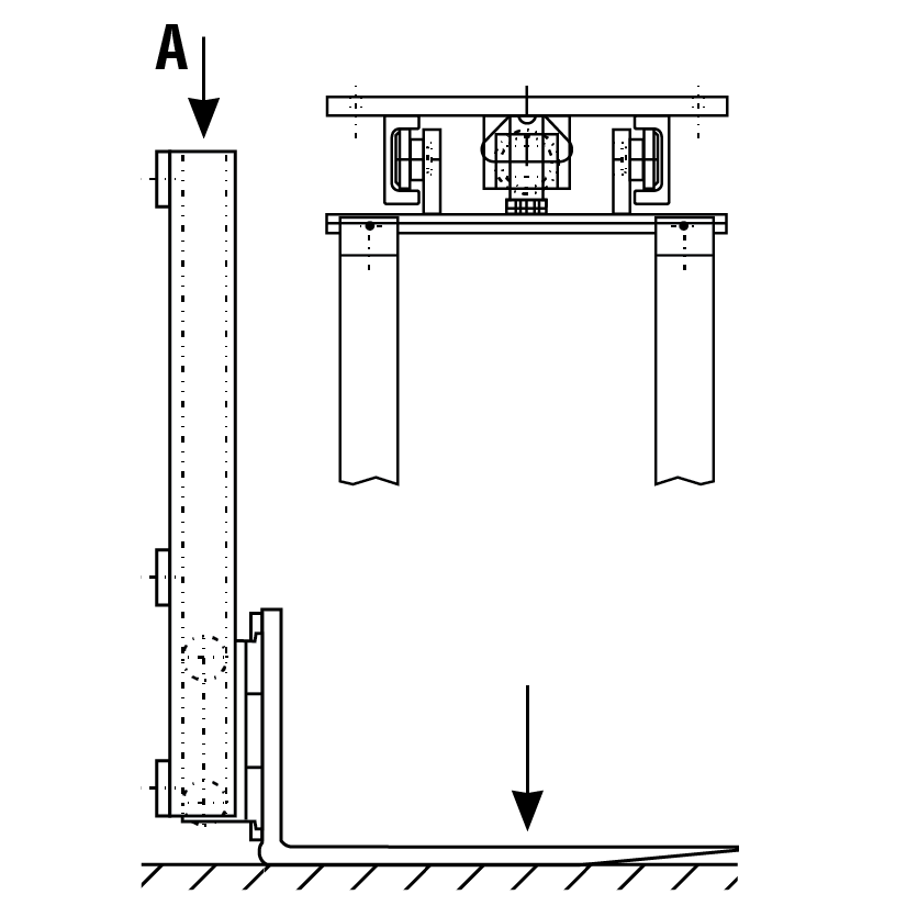
Adjustable Clamp System
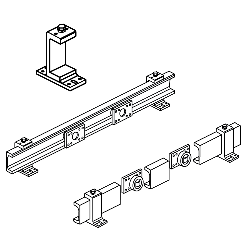
Handling Units
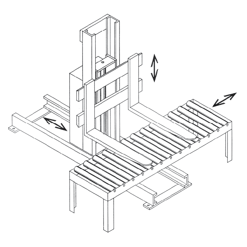
Horizontal Telescope
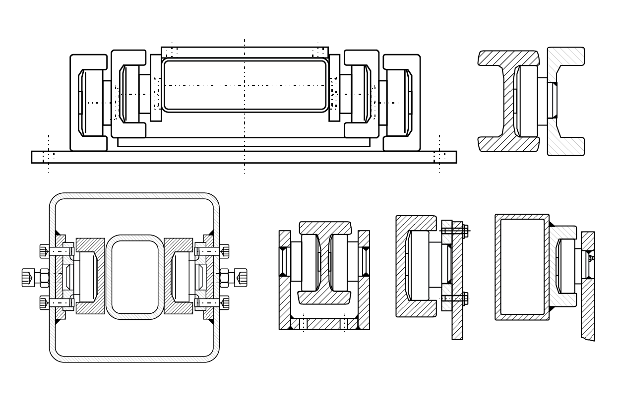

Mounting Instructions
- The overall system clearance should be 1.524 mm to 3.048 mm Inner Rail Distance = Saddle Width + (1.524 mm to 3.048 mm)
- Verify that the axial bearing is aligned parallel to the rail; especially in vertical operations

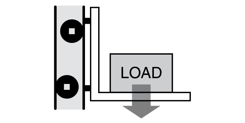
Technical • Life Calculation
Important Notice about Lifetime Calculations
There is no known formula for accurately and reliably calculating the actual lifetime of a linear or rotary bearing system.
The formulas within this section are solely based upon the statistical probability of success. It is important to recognize and distinguish between formulas of absolute certainty and probability.
Even though these formulas are not absolutely certain, they have been generally accepted as the best available method for determining bearing lifetime by the International Organization for Standardization (ISO), as well as its membership bodies; including, but not limited to: American National Standards Institute (ANSI), Deutsches Institut für Normung (DIN) & Japanese Industrial Standards Committee (JISC).
Static & Dynamic Load Ratings
PBC Linear uses the two internationally accepted methods for calculating the Rated Lifetime, Static, and Dynamic Capacities. Per the international standard, all lifetimes are calculated to an L10 life of 100 km (105 meters or ≈ 3.94 million inches). The two standards used are:
- ISO76 Rolling Bearings – Static Load Ratings
- ISO281 Rolling Bearings – Dynamic Load Ratings & Rating Life
Note: Some suppliers may choose to rate their bearings based upon a useful life of less than 100 km or a probability of success less than 90%. This causes their bearings to falsely appear to have a higher static and dynamic load capacity. If a catalog does not specifically note L10 = 100 km, caution should be used when comparing load capacity or life values between suppliers. The most commonly used values are L10 = 50 km and L25 = 50 km. For comparison, at L10 = 100 km, an example bearing has a maximum static load of 1,000 N. That exact same bearing as an L10 = 50 km maximum static load of ≈2,300 N and an L25 = 50 km maximum static load of ≈4,600 N!
In summary, the static load ratings are defined as the maximum applied load (or moment) which will result in the permanent deformation which does not exceed 1/10,000 of the diameter of the rolling element (ball or rod) within the bearing. The basic dynamic load rating, C, is the load of a constant magnitude and direction, which a sufficiently large number of apparently identical bearings can endure for a basic rating life of one million revolutions. It’s important to note that both the static and dynamic values are determined though ISO-Approved formulas. These formulas take into account several factors, including the design, internal geometry, material type, material quality, and lubrication type.
Note: Additional factors are provided so that the estimated lifetime (default = 100 km) and/or the probability of success (default = 90%) can be changed from their default value to any desired value.
Operating Lifetime
The Operating Life (or Operating Lifetime) is the actual life achieved by a rolling bearing. The actual lifetime typically varies from the calculated lifetime, sometimes significantly. It is not possible to accurately and reliably determine the actual Operating Life through calculations due to the large variety of operating and installation conditions. The most reliable method to achieve an approximation is by comparing the current application to similar applications. Primary factors which can negatively affect the life and are generally not included in calculations are:
- Contamination within the application
- Inadequate or improper lubrication
- Operational conditions different from calculated values, including unexpected forces and moments
- Insufficient and/or excessive operating clearance between the roller and guideway
- Excessive interference between roller and guideway (typically due to misalignment or excessive preload)
- Temperature out of range
- High shock loads (exceeding static load capacity)
- Vibration (which causes false brinelling resulting from fretting)
- Short stroke reciprocating motion (also causes False Brinelling)
- Damage caused during installation or from improper handling
- Improper mating surface hardness (when not used with a PBC Linear rail)
Terms, Definitions & Symbols
The following variables are used within the equations listed on the following pages:
Fy app = Force applied in the Y direction (radial force), N
Fz app = Force applied in the Z direction (axial force), N
Mx app = Moment applied about the X axis, N
My app = Moment applied about the Y axis, N
Mz app = Moment applied about the Z axis, N
FMAX = Maximum allowable force in the Y direction (radial force), N
Fz MAX = Maximum allowable force in the Z direction (axial force), N
Mx MAX = Maximum allowable moment about the X axis, N • m
My MAX = Maximum allowable moment about the Y axis, N • m
Mz MAX = Maximum allowable moment about the Z axis, N • m
Da = Rolling contact diameter, from product tables, mm
fh = Shaft (rail) hardness reduction factor
fl = Required Lifetime (km) reduction factor
fr = Reliability reduction factor
fss = Short stroke reduction factor
L10 = Basic rating life, km (103 m)
Pr = Equivalent radial (Fy) load, N
s.f = Safety factor
Note: PBC Linear has chosen to depart from the nomenclature standards used by ISO. Instead, PBC Linear uses a convention that is more in line with other PBC Linear products. This ensures that all PBC Linear products use the same naming conventions, making it easier to compare multiple products from different product families. The Y direction (radial force) and Z direction (axial force) are dependent upon the orientation of the wheel bearing.

\( F_d \) = Dynamic capacity (LC)
\( F_z \) = Axial capacity
\( F_y \) = Radial capacity
\( M_x, M_y, M_z \) = Moment capacities
Conversions
newton (N) • 0.2248 = lb.
(lb) meter • 0.0397 = inch
newton - meter (N-m) • 8.851 = in.-lb.
Derivation
The lifetime formula within ISO 281 gives the life in millions of revolutions. The conversion from rotary life to linear life is done using the conversion factors listed in the following three equations. This derivation applies to both individual rollers and carriages. Lrev and Ldistance represent the lifetime of the bearing in revolutions and linear distance, respectively.
Note: Attention must be paid to units of measure, especially when considering products from different manufacturers. All of the lifetime formulas within this section yield results in kilometers; however, not all companies follow the same standard. Some companies may express life in meters or 100’s of kilometers.
Eq. 1
\(L_{\text{Distance}} [1 \cdot 10^5 \, \text{m}] = L_{\text{Rev}} [1,000,000 \, \text{rev}] \cdot \left(3.14 \cdot D_a \, \left[\frac{\text{mm}}{\text{rev}}\right]\right) \cdot \left(\frac{1 \cdot 10^5 \, \text{m}}{1,000,000,000} \, \left[\frac{\text{m}}{\text{mm}}\right]\right)\)
Eq. 2
\(L_{\text{Distance}} [1 \cdot 10^5 \, \text{m}] = L_{\text{Rev}} \cdot (0.0314 \cdot D_a)\)
Eq. 3
\(L_{\text{Distance}} [\text{km}] = 100 \cdot L_{\text{Rev}} \cdot (0.0314 \cdot D_a) = 3.14 \cdot D_a \cdot L_{\text{Rev}}\)

Individual Rollers – All products except Hevi-Rail Rollers
Most of the individual rollers within this catalog are Radial Ball Bearings. The following formulas should be used for all individual bearings except Hevi-Rail bearings (which are roller bearings). This formula calculates the basic rating life (L10 life), which does not take into account any reduction factors based upon the application.
Eq. 4
\(L_{10} [\text{km}] = 3.14 \cdot D_a \cdot \left(f_L \cdot f_H \cdot f_{SS} \cdot \frac{F_{y\ \text{max}}}{P_r}\right)^3 \cdot (f_R)\)
Eq. 5
\(P_r = X \cdot F_{y\ \text{app}} + Y \cdot F_{z\ \text{app}}\)
The values for X & Y can be found using the table listed below.
Values of X & Y for Radial Ball Bearing Life Formula
| Product | \( \frac{F_{z\ \text{app}}}{F_{y\ \text{app}}} \leq \varepsilon \) |
\( \frac{F_{z\ \text{app}}}{F_{y\ \text{app}}} > \varepsilon \) |
\( \varepsilon \) |
||
|---|---|---|---|---|---|
| X | Y | X | Y | ||
| Commercial Rail (all sizes) | 1 | 0 | 0.41 | 0.87 | 0.68 |
| Hardened Crown Rollers | 1 | 0 | 0.41 | 0.87 | 0.68 |
| Integral-V (IVT) (Compact Linear Guides) | 1 | 0.78 | 0.63 | 1.24 | 0.80 |
| Integral-V (IVT) (all other sizes & types) | 1 | 0.78 | 0.63 | 1.24 | 0.80 |
| Redi-Rail (all sizes & types) | 1 | 0.78 | 0.63 | 1.24 | 0.80 |
| Steel-Rail (all sizes & types) | 1 | 0.78 | 0.63 | 1.24 | 0.80 |
| V-Rail (all sizes) | 1 | 0.78 | 0.63 | 1.24 | 0.80 |
Individual Rollers – Hevi-Rail Rollers
Hevi-Rail bearings are roller bearings, as opposed to radial ball bearings. The formulas are very similar to the formulas shown above, with only some minor changes.
Note: Hevi-Rail rollers are combined bearings. Essentially two bearings combined into one. Life calculations should be performed for both the radial and the axial bearing.
Eq. 6
\(L_{r_{10}} [\text{km}] = 3.14 \cdot D_a \cdot \left(f_L \cdot f_H \cdot f_{SS} \cdot \frac{F_{y\ \text{max}}}{F_{y\ \text{app}}}\right)^{\frac{10}{3}} \cdot (f_R) \)
Eq. 7
\(L_{a_{10}} [\text{km}] = 3.14 \cdot D_a \cdot \left(f_L \cdot f_H \cdot f_{SS} \cdot \frac{F_{z\ \text{max}}}{F_{z\ \text{app}}}\right)^{\frac{10}{3}} \cdot (f_R) \)
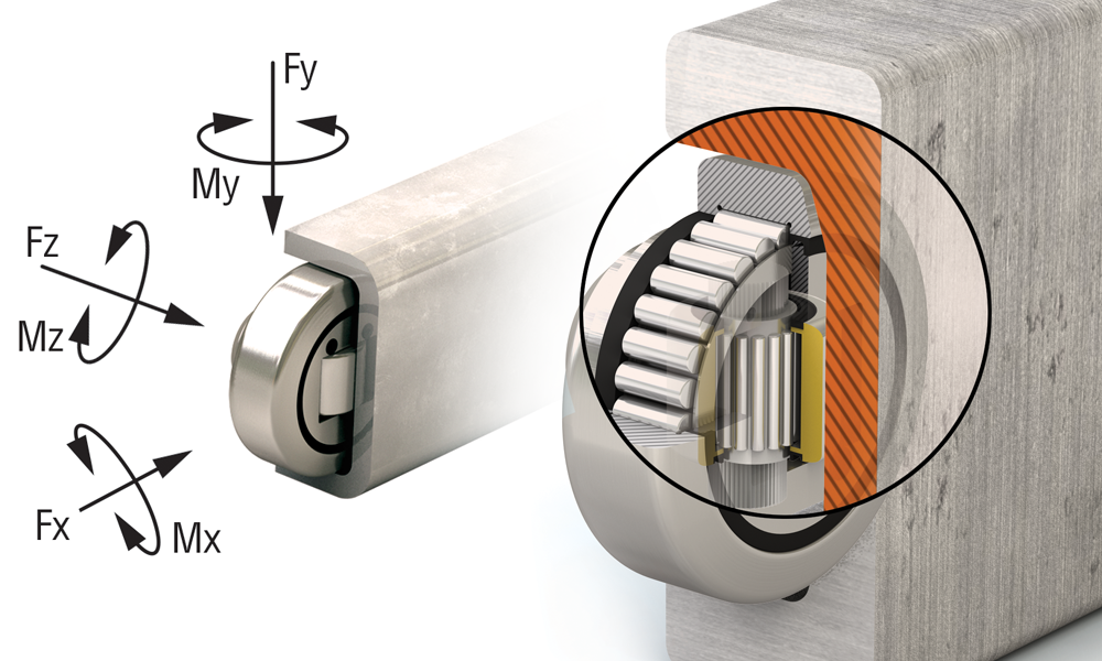
Carriage Assemblies
Formulas for calculating the estimated lifetime for carriage assemblies are fundamentally similar to the calculations for the individual rollers. The most accurate method for determining the life of a carriage assembly is to create a free body diagram for the carriage and determine the axial, radial, and moment load applied to each individual roller. This method is cumbersome and is usually only required in the most severe of circumstances. In most cases, the carriage assembly can be treated as a rigid body and calculations can be completed based upon the load ratings for the entire carriage:
Eq. 8
\(L_{10} [\text{km}] = 100 \cdot \left(f_L \cdot f_H \cdot f_{SS} \cdot \left(\frac{1}{\frac{F_{y\ \text{app}}}{F_{y\ \text{max}}} + \frac{F_{z\ \text{app}}}{F_{z\ \text{max}}} + \frac{M_{x\ \text{app}}}{M_{x\ \text{max}}} + \frac{M_{y\ \text{app}}}{M_{y\ \text{max}}} + \frac{M_{z\ \text{app}}}{M_{z\ \text{max}}}}\right)\right)^3 \cdot (f_R)\)
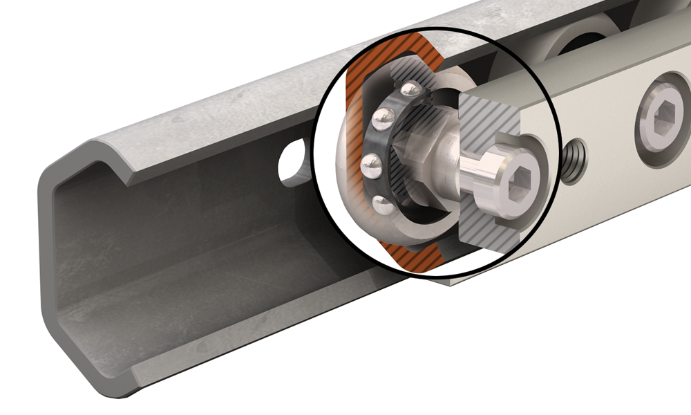
Safety Factor
All individual rollers and carriages are subject to use a balancing formula, which ensures an adequate product life. The following formulas should be used for all CRT products:
Eq. 9
\(\text{Carriages:} \quad \frac{1}{\text{s.f.}} \geq \frac{F_{y\ \text{app}}}{F_{y\ \text{max}}} + \frac{F_{z\ \text{app}}}{F_{z\ \text{max}}} + \frac{M_{x\ \text{app}}}{M_{x\ \text{max}}} + \frac{M_{y\ \text{app}}}{M_{y\ \text{max}}} + \frac{M_{z\ \text{app}}}{M_{z\ \text{max}}}\)
Eq. 10
\(\text{Individual Bearings:} \quad \frac{1}{\text{s.f.}} \geq \frac{F_{y\ \text{app}}}{F_{y\ \text{max}}} + \frac{F_{z\ \text{app}}}{F_{z\ \text{max}}}\)
Where the safety factor value can be determined using the following table.
Recommended Safety Factor (s.f.)
| Duty | Shock/Vibration | Reverse Frequency | Contamination | S.F. |
|---|---|---|---|---|
| Very Light | None | Smooth & Low | None | 1.0 – 1.2 |
| Light | Light | Light | Light | 1.2 – 1.5 |
| Medium | Medium | Medium | Medium | 1.5 – 2.0 |
| Heavy | Heavy | High & Fast | Heavy | 2.0 – 3.5 |
Note: The table above contains suggested safety factors based upon the most commonly encountered adjustment criteria. Additional criteria may require raising the safety factor.
Minimum Load Notice
It is possible to apply too small of a load to a bearing/carriage. In this case, there is a possibility of the outer ring slipping or the roller lifting off the track. This can cause unexpected vibration or skidding, which reduces the life of the bearing. Therefore, the following condition should be met under dynamic load conditions:
There is no minimum load requirement under static conditions.
Eq. 11
\(\text{Minimum Dynamic Load} \quad \rightarrow \quad \frac{F_{y\ \text{max}}}{F_{y\ \text{app}}} \leq 50\)
Heavy Load Notice
It is also possible to over load the bearings. Extra-heavy loads can cause unexpected stress concentrations in the bearing or railway, which reduce the actual lifetime below the minimally acceptable level. These stress concentrations typically come from unexpected vibrations within the application or unexpectedly high preload forces caused by misalignment, damage, or thermal expansion. In these cases, a larger safety factor should be used.
Eq. 12
\(\text{Use Caution} \quad \rightarrow \quad P_{re} > 0.5 \cdot C_r\)
Note: Although typically applying to linear motion rolling bearings, ISO 14728-1 states that the above equation should be followed. It should be treated as a rule as opposed to a guideline.
If the product under consideration is a carriage (slider) assembly and Pr > 0.5 • Cr, then it is recommended to consider the axial, radial and moment load applied to each individual roller to ensure each roller still has an adequate safety factor.
Shaft/Rail Hardness Factor, fH
It is possible to use a softer rail material in combination with PBC Linear CRT products; however, it is necessary to reduce the static and dynamic load capacities of each product. The reduced load capacity is known as the “Effective Load Capacity,” which can be calculated using the formula below. The reduction factor, fH, can be determined using the table below.
For easy reference, some of the most common materials
have been plotted on the on the table below:
Eq. 13
\(\text{Dynamic} \quad \rightarrow \quad F_{Y\text{ Eff}} = F_Y \cdot f_H\)
Eq. 14
\(\text{Static} \quad \rightarrow \quad F_{OY\text{ Eff}} = F_{OY} \cdot f_H\)
Approximate Comparison of Common International Materials
For easy reference, some of the most common materials have been plotted on the table below:
| # | TYPE | EN NAME | EN # | ASTM/AISI | TYPICAL HARDNESS | fH |
|---|---|---|---|---|---|---|
| 1 | Steel | C60 | 1.0601 | 1060 | 60-62 | 1.0 |
| 2 | Steel | 52-3 | 1.0570 | 1024 | 19-22 | 0.1 |
| 3 | Stainless Steel | X46 Cr13 | 1.4034 | 420 | 51-53 | 0.7 |
| 4 | Stainless Steel | X90 CrMoV18 | 1.4112 | 440B | 53-55 | 0.8 |
| 5 | Stainless Steel | X105 CrMo17 | 1.4125 | 440C | 59-61 | 0.95-1.0 |
Note: The values listed in the above table should be considered for reference only. It is critical that individual suppliers are contacted to ensure an accurate hardness rating. Depending upon the supplier, “hardness” can actually be the minimum, maximum, or average value. The wrong interpretation can have unexpected consequences for the application. When given the choice, PBC Linear recommends using the “minimum hardness” when determining the reduction factor as this is the most conservative method.
- Material Types may not be an exact match. PBC Linear has carefully reviewed the material standards and has determined that if there is not an exact match, the listed materials are the closest approximation. A material specialist should be consulted before translating one material type to another.
- Different suppliers may have alternate ranges for material hardness, depending upon their heat treating process. Consult manufacturer’s specifications for a more exact number/range.
Static & Dynamic Reduction Factors for Lower Raceway Hardness
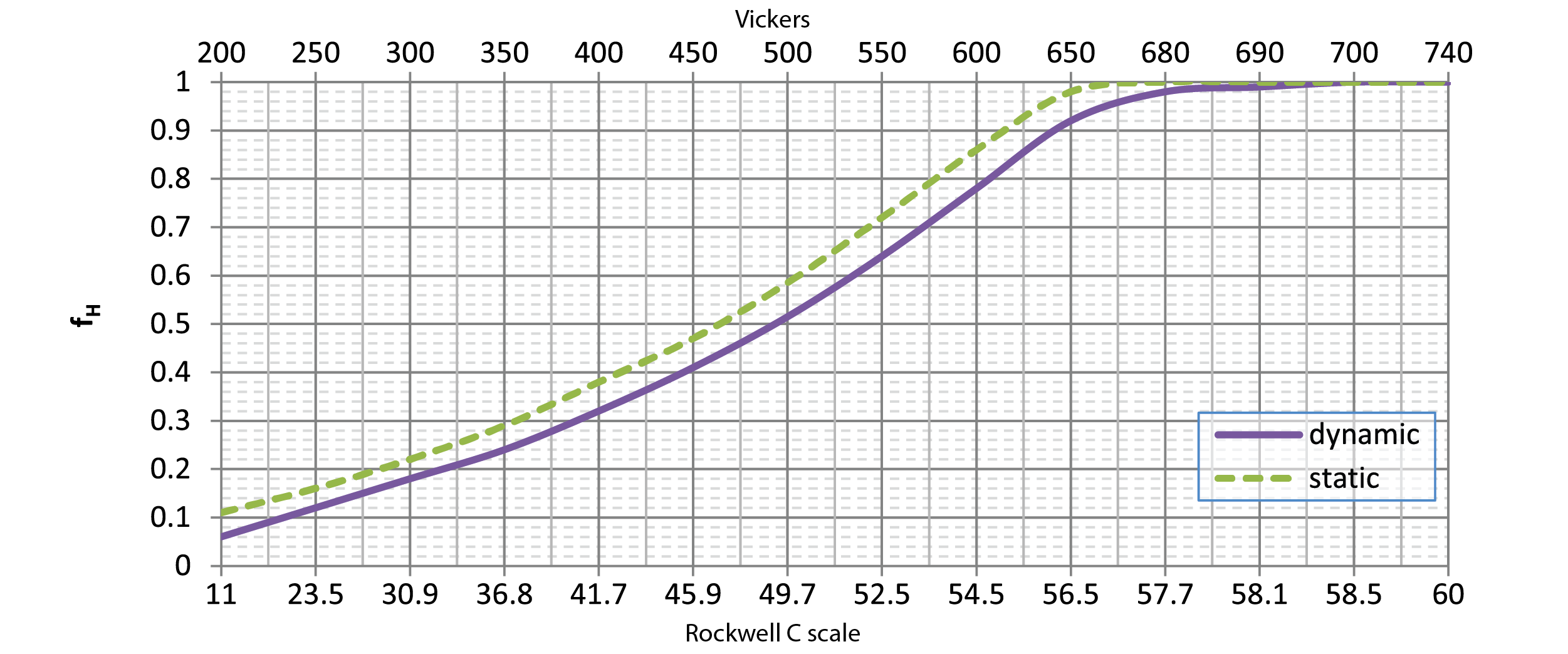
Required Lifetime (km) Factor, fL
The standard lifetime formulas listed within this catalog describe an L10 life based upon 100 km, in accordance to the applicable ISO standards. Sometimes 100 km is either excessive or shy of the target life of a machine and the required lifetime needs to be adjusted. An appropriate adjustment factor can be found using the chart.
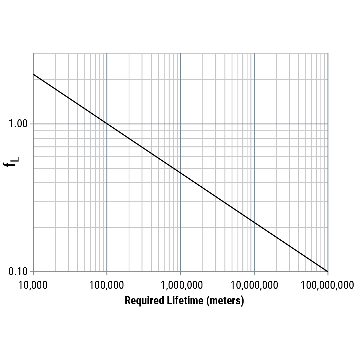
Reliability Factor, fR
| Reliability | Ln | fR |
|---|---|---|
| 50% | L50 | 5.04 |
| 60% | L40 | 3.83 |
| 70% | L30 | 2.77 |
| 80% | L20 | 1.82 |
| 90% | L10 | 1.0 |
| 95% | L5 | 0.64 |
| 96% | L4 | 0.55 |
| 97% | L3 | 0.47 |
| 98% | L2 | 0.37 |
| 99% | L1 | 0.25 |
| 99.2% | L0.8 | 0.22 |
| 99.4% | L0.6 | 0.19 |
| 99.6% | L0.4 | 0.16 |
| 99.8% | L0.2 | 0.12 |
| 99.9% | L0.1 | 0.093 |
| 99.92% | L0.08 | 0.087 |
| 99.94% | L0.06 | 0.080 |
| 99.95% | L0.05 | 0.077 |
The L10 Life Formulas are a statistical probability formula with a success rate of 90%. Sometimes an L10 life (90% success) is just not good enough and the formulas need to be modified in order to have a higher probability of success. In this case, choose the desired reliability rate and insert the fR value into the life equation.
Short Stroke Factor, fss
In the case that the travel distance is low, a short stroke reduction factor must be included. In general, this factor only applies when the stroke is less than 2x the carriage length. In the case of individual bearings, use two full revolutions of the bearing.
Eq. 15
\(\text{Stroke ratio, carriage (slider)} = \frac{\text{stroke [mm]}}{\text{carriage length [mm]}}\)
Eq. 16
\(\text{Stroke ratio, individual bearing} = \frac{\text{stroke [mm]}}{\pi \cdot D_p \, \text{[mm]}}\)
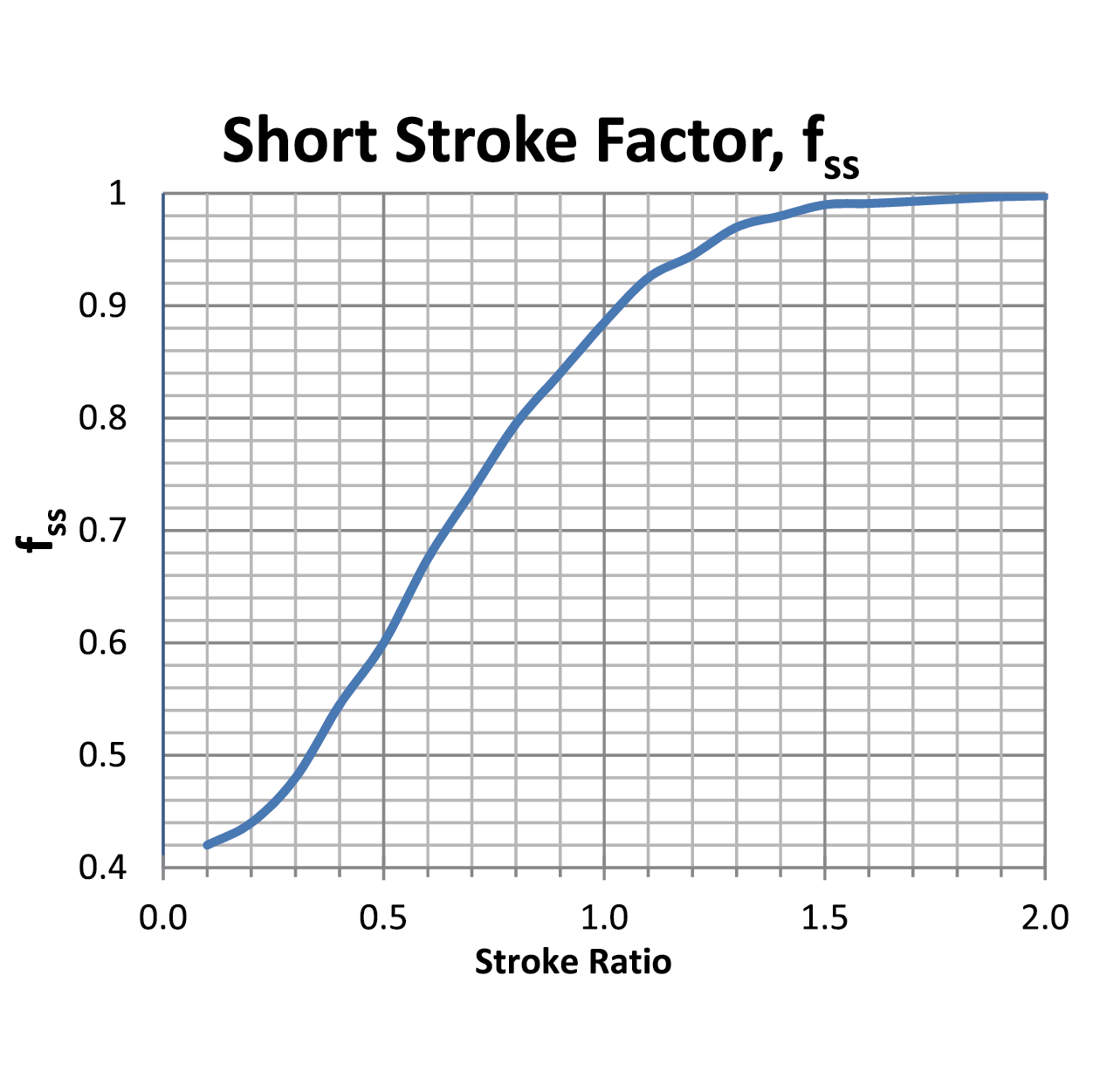
Technical • Installation

General Installation
As a general rule, all of the products within the catalog have a higher radial (Fy) than axial (Fz) load capacity. Whenever possible, designers should attempt to orient the bearings so the primary applied load is in the radial direction.
Commercial Rail
Commercial Rail is typically used in applications which require low to moderate accuracy. It is generally not necessary to use any advanced manufacturing or assembly techniques to secure this rail system into place.
Note: If an assembly plan requires Commercial Rail to be installed with dial indicators, calipers, or other sensitive measuring equipment, then likely this product has probably been over-specified for an application. Consider using a more accurate product for these applications, such as the V-Guide System, Redi-Rail, Integral-V (IVT), or Steel Rail.
Hardened Crown Roller Rail
Note: If an assembly plan requires Hardened Crown Roller rails to be installed with dial indicators, calipers, or other sensitive measuring equipment, then it is likely this product has probably been over-specified for an application. Consider using a more accurate product in these applications, such as the V-Guide System, Integral-V (IVT), Redi-Rail, or Flexible Steel Rail.
Redi-Rail
The Redi-Rail product is very versatile and can be used in applications that require low accuracy or moderate-high accuracy. In applications that require low accuracy, no special installation, and alignment procedures are needed. In applications that require moderate to high accuracy, use advanced assembly techniques similar to those used for installing profile rail guideways.
Note: Refer to the PRT (Profile Rail Technology) catalog for more detailed information related to advanced assembly techniques.
Hevi-Rail
Hevi-Rail is typically used in applications that require moderate accuracy. There are two common methods for installing Hevi-Rail: Welding & Clamp Flanges.
Welding
The preferred method of welding Hevi-Rail, Flange Plates, and Hevi-Rail Clamp Flanges is MIG Welding. Please follow the guidelines listed below when MIG welding Hevi-Rail, Flange Plates and Hevi-Rail Clamp Flanges.
- Use a metal brush or grinder to remove rust or paint from surface to be welded.
- Bevel joint edges on metals thicker than 3/8" to ensure the weld fully penetrates to the base of the metal. (HVR-2, HVR-3, HVR-4, HVR-5 HVR-6, HVRI-08, HVRI-09, HVRI-10, and HVRI-11).
- Ensure that grounding clamp is engaged in clean metal.
- When welding HVR-S, HVR-0, HVR-1, and HVRI-07 sections of Hevi-Rail it is recommended to use 0.03" diameter wire. A preferable grade wire for mild steel is ER70S-3.
- When welding thick sections of Hevi-Rail, it is recommended to use 0.035"–0.045" ER70S-3 wire. Weld at a higher heat level to obtain a deep penetration. This is recommended for HVR-2, HVR-3, HVR-4, HVR-5 HVR-6, HVRI-08, HVRI-09, HVRI-10, and HVRI-11.
- A 75% Argon/25% Carbon Dioxide mix is a preferable general purpose shielding gas when welding mild steels like Hevi-Rail.
- Know your load calculations, when in doubt meet with your structural or mechanical engineer.
- Destructive testing facilities are recommended for testing weld strength. Periodic destructive testing ensures that the welding equipment and welding practices are yielding safe and strong welds.
- Never weld a mild steel Hevi-Rail product to a dissimilar metal such as cast iron or stainless steel.
Clamp Flanges
When using bolts to hold a Clamp Flange to Hevi-Rail HVR-1, HVR-2, HVR-3, HVR-4, HVR-5, or HVR-6, it is recommend to drill a detent in the top of the rail where the screw seats. Many customers use a drill point smaller than the minor diameter of the tap diameter to put a point in the rail. This is preferred in systems that have vibrations and harmonics in its environment. Some customers use bolts to align and assemble the system, then weld the clamp to the rail.
V-Guide
V-Rail is typically used in applications that require low to moderate accuracy. The installation accuracy is primarily limited by the accuracy of the mounting surface. It is possible to successfully install V-Rail onto as-extruded bars and plates, or to rolled metal bars and plates. These materials typically do not have very tight dimensional, parallelism, flatness, and straightness tolerances. The loose tolerances add to the overall tolerance stack-up, which reduces the installation accuracy.
A higher grade of accuracy can be achieved by machining the mounting plate, typically through a milling or grinding process. It is possible to achieve an accuracy rating as high as ± 0.025 mm (± 0.001 in.) using machine tool design and assembly techniques. In this case, the mounting surface must be meticulously prepared, and reference edge or dowel pins should be used for alignment purposes.
Note: Integral-V (IVT) products eliminate this alignment process. If an application requires two parallel rails, PBC Linear highly recommends the consideration of the IVT products. Customers have reported significant Total Installed Cost (TIC) savings that have been achieved through the use of IVT products.
General Notes
Handling
Proper handling of PBC Linear products is critical to ensure specified product performance, product life, and to prevent accidental injury. Some products come from the factory with a clearance type preload. These carriages will freely slide if the rail is not kept horizontal. Special attention must be paid when installing the rail overhead or in a vertical orientation.
Special care must also be given to long length units. Single point lifting some products may cause enough bend as to result in permanent, plastic deformation to the railway. Always use suitable lifting equipment that provides enough support to minimize deflection.
Storage
Proper storage is critical in order to maintain an adequate product shelf life. If immediate installation is not possible or practical, it is best to store the product within the package provided by (or designated by) PBC Linear. The product and package should be stored in a horizontal orientation and environmental extremes (high temperature, low temperature, and high humidity) should be avoided. It may be necessary to lubricate steel components during prolonged storage in order to prevent corrosion.
Securing Fasteners
PBC Linear makes no specific recommendation as to whether or not thread-locking fluid (i.e. Loctite®), lock nuts, lock washers, etc., should be used within a given application. Sound engineering fundamentals and company policies should dictate the use of anti-vibration components and technology. Some common reference materials include, but are not limited to:
- Your company’s policies and/or engineering specifications
- Marks’s Standard Handbook for Mechanical Engineers, published by McGraw-Hill (English)
- Machinery’s Handbook, published by Industrial Press (English)
- Roloff/Matek Maschinenelemente, published by Vieweg (German)
Fastener Quantity
It may not be necessary to use a fastener within every supplied fixing hole. This is especially true for applications carrying a light load (high factor of safety). Engineering statics equations can be used to determine the amount of deflection within a rail if not all fixing holes are used. Modern tools, such as FEA, can also be used to speed up this process.
Welding
The recommendations and guidelines listed herein are recommendations only. Always follow your specific company’s policies, welding equipment manufacturer’s instructions, guidelines established by national standards agencies (i.e. ANSI/ DIN) and city/state/federal laws or civil guidelines related to proper welding practices. Improper application or installation of PBC Linear products can result in property damage, death, or serious bodily injury.
Note: Improper installation of carriages with spring-loaded lubricators can permanently damage the lubricator material. Damage caused by improper installation is not covered by PBC Linear warranty.
Initial Lubrication
After installation, follow the initial lubrication instructions located within this catalog or at pbclinear.com. All products are shipped with a preservative material, which should not be considered a true performance lubricant. Lubricant should be added before initial use.
Painting/Powder Coating
Most PBC Linear products can be painted or powder coated after installation to match the aesthetic appearance of the parent structure. It is highly recommended that the bearing’s raceway be masked during this process. These coatings will typically not withstand the pressure of a typical operation and will flake off. These flakes will act as bumps causing the rollers to experience unplanned vibration. This can cause an unexpected shortening of the life of the rollers/carriage.
Technical • Lubrication
Roller Lubrication
All smaller rollers (in the Redi-Rail, IVT, V-Guide, Commercial Rail, Hardened Crown Roller families, and smaller diameter Hevi-Rail bearings) are lubricated internally for long life. No additional lubrication is necessary. The rollers are sealed (or shielded) against the operating environment to prevent egress of lubricant, and prevent ingress of contaminants. Some larger rollers (in the Hevi-Rail family) are supplied with a grease access point and can be re-lubricated using a zerk fitting.
Raceway/Guideway Lubrication
To ensure long life, it is necessary to have a thin film of lubrication on the Raceway/Railway at all times. When properly applied, lubrication:
- Reduces wear
- Reduces stress on the contact surfaces
- Reduces friction (and therefore heat buildup)
- Allows for operation at specifications in this catalog (de-rating is required for un-lubricated applications)
- Helps protect the metal surfaces against corrosion (rust and fretting corrosion)
Lubrication Type
Technical, environmental, ecological, and economic factors will determine whether oil or grease should be used in an application. One of the most significant factors in the lubrication selected is the environmental conditions. If extreme conditions are expected, it is highly recommended that a representative from a lubrication company is consulted. This includes heavy contamination when the expected particle size is smaller than 0.1 mm (0.005 in.) as small particles can more easily bypass seals and wipers.
⚠ CAUTION
The compatibility of lubricants must always be checked! This check should be done under both static and dynamic conditions and within the operating environment. Some lubricants may have unexpected, negative reactions with the plastics, elastomers or non-ferrous metals within the products. It is possible to draw upon previous and practical experience or guidelines from the lubricant manufacturer. When in doubt, consult the lubricant manufacturer.
Initial Lubrication (during installation)
PBC Linear Guides and Raceways are shipped with a preservative lubrication applied to the raceway. During installation, it is necessary to apply additional lubrication. Provided there are no application conflicts, PBC Linear recommends high quality lithium soap grease as the initial lubricant. This grease should be applied to the entire raceway, not just the portion used during normal operation. Oil or grease may be used for re-lubrication.
Note: Coated/Plated rails, Commercial Rail, Hardened Crown Roller, and HeviRail rails are typically shipped without any preservative lubrication. See the Hevi-Rail section for more details: sandblast and lightly oiled option is available for Hevi-Rail.
Periodic Lubrication/Maintenance
The lubrication interval is dependent on many operating and environmental conditions, such as load, stroke, velocity, acceleration, mounting position/orientation, type of lubrication used, temperature, humidity, UV exposure, etc. The actual lubrication interval should be determined by tests conducted under actual application conditions.
While the actual lubrication intervals are application specific and determined only through testing, the following guidelines can typically be used as a starting reference point under normal conditions:
- Re-lubrication every 1,000 km; 50,000 cycles or six months (whichever occurs first).
Oil Filled Polymer Lubricator
Some PBC Linear products offer a high quality polymer lubricator. PBC Linear uses an advanced, oil filled porous polymer, which has been tested to show better performance and longer life than similar wiper/lubricators made of oil or grease filled felt. In some applications, this special lubricator will last the life of the application without additional re-lubrication.
This lubricant within the polymer is NSF Registered for both H1 & H2 applications (Direct and Indirect contact with food). It can also be used for wash down and industrial applications. The lubrication within the polymer contains corrosion inhibitors, anti-oxidants, and extreme pressure (E.P.) additives. The table below shows some specific properties for the lubricant.
Properties for Lubrication in Advanced Oil-Filled Plastic
| Upper Temp Limit | Lower Temp Limit | Specific Gravity | Viscosity at 40°C cSt | Viscosity at 100°C CST |
|---|---|---|---|---|
| 99° (210°F) | -40° (-40°F) | 0.86 | 150 | 16.5 |
Used Lubricants
Used lubricants should be disposed of using environmentally-friendly methods. Most lubricant manufacturers have guidelines regarding their allowable storage, use, and disposal. In addition, some countries have regulations regarding storage, use, and disposal of lubricants for occupational safety and/or environmental protection. Furthermore, some companies may have adopted internationally accepted quality and standards policies (i.e. ISO14001), which will further regulate the use of lubricants within an application.
These guidelines and regulations must be followed. Care should be exercised as to not specify a lubricant which is forbidden.
Lubrication Failure
Contamination and lack of lubrication are the two primary causes of (ball based) linear guide failures. Lack of lubrication will cause fretting corrosion, which can cause permanent system damage and eventually lead to system failure. As it applies to this product, fretting corrosion is a form of damage caused as a combination of corrosion and abrasive wear. Fretting corrosion can typically be seen as a reddish discoloration on either mating raceway (track or roller). Fretting corrosion can sometimes be confused with rust. Both are signs that additional lubrication is necessary and the re-lubrication period must be decreased.
Operation in an Un-Lubricated State
While not recommended, it is possible to run most systems without lubrication; however, there will be significant reductions to maximum load, maximum speed, and expected life. The table below shows that a typical un-lubricated system will have a significantly reduced maximum load and a reduced maximum speed when compared to a properly lubricated system.
Typical Reductions for Max Load & Speed for Un-Lubricated Systems
| Product | Lubricated | Un-Lubricated | Reduction | ||
|---|---|---|---|---|---|
| A | Max Load | kg | 100 | 25 | 75% |
| Max Speed | m/s | 2 | 1.5 | 25% | |
In addition to significant reductions in maximum load and speed, un-lubricated systems will also experience an extreme reduction in expected life. The table below shows the expected life for both a lubricated and un-lubricated system for two different products with two different applied loads. The approximate reduction in lifetime has also been calculated.
Typical Life Reductions for Un-Lubricated Systems
| Product | Lubricated | Un-Lubricated | Reduction | ||
|---|---|---|---|---|---|
| B | Applied Load 1 | kg | 45.4 | 45.4 | – |
| Life 1 | m | 5,410,200 | 88,900 | ≈ 98% | |
| Applied Load 2 | kg | 22.7 | 22.7 | – | |
| Life 2 | m | 22,860,000 | 533,400 | ≈ 98% | |
| C | Applied Load 3 | kg | 45.4 | 45.4 | – |
| Life 3 | m | 50,800,000 | 863,600 | ≈ 98% | |
| Applied Load 4 | kg | 90.7 | 90.7 | – | |
| Life 4 | m | 8,382,000 | 152,400 | ≈ 98% | |
Note: Actual performance will vary depending upon specific application conditions. PBC Linear has removed the actual product name from the examples listed above as the results may not be repeatable, depending upon specific application conditions. While these values are typical, specific reductions should be determined by tests conducted under actual application conditions.
Technical • General
Operating Temperature
The Cam Roller products shown in the catalog have a wide operating temperature limit. All of the products within this catalog can be used within the following range: -20°C to +80°C (-4°F to 176°F). For applications outside of this range, first refer to the specifications for individual products. If a wider range is still needed, please contact our applications engineering group using the contact information below.
The temperature range for these products is limited by the lubricant, engineered polymer wipers, and composite cover materials. In most cases, changing the lubricant or the engineered polymer will extend the operating temperature limit for the product.
Velocity & Acceleration
For maximum velocities, check the product specifications. The maximum velocities will range from 0.76 m/s up to 12 m/s. Higher speeds may be possible, but may not be sustainable. Please contact our applications engineering group for sustained speeds above 12 m/s (33 ft/s).
Unless otherwise noted, the maximum possible acceleration of all CRT products is approximately 5 G’s (50 m/s2, 160 ft/ s2). Higher accelerations are possible, but may not be sustainable. Please contact our applications engineering group for sustained accelerations above 5 G’s.
Safety guidelines
Product Safety
PBC Linear products are designed and manufactured to the most current level of technology and research. If the bearing (or linear guide) arrangement is designed, handled, installed, and maintained correctly, then they do not give rise to any known or direct hazards. Misapplication, improper handling, improper installation, or improper maintenance may lead to premature product failure, which may have unintended consequences.
Read & Follow Instructions
This publication describes standard products. Since these are used in numerous applications, PBC Linear cannot make a judgment as to whether any malfunctions will cause harm to persons or property. It is always, and fundamentally, the responsibility of the designer and user to ensure that all specifications are observed, and that all necessary safety information is communicated to the end user. This applies in particular to applications in which product failure and/or malfunction may constitute a hazard to human beings.
Symbols
This publication uses several hazard, warning and notification symbols which are defined in accordance to ANSI Z535.6-2006.
Notifications
© PBC Linear 2014. All rights reserved. No part of this publication may be reproduced, stored in a retrieval system, or transmitted in any form or by any means without the prior written permission of PBC Linear
The data and specifications in this publication have been carefully compiled and are believed to be accurate and correct. However, it is the responsibility of the user to determine and ensure the suitability of PBC Linear products for a specific application. PBC Linear makes no warranty, expressed or implied, regarding the non-infringement, merchantability, or fitness for a particular purpose of the products. No liability is assumed with respect to the use or misuse of the information contained herein. The only obligation on part of PBC Linear will be to repair or replace without charge, any defective components if returned promptly. No liability is assumed beyond such replacement. The appearance, specifications, and other information are subject to change without notice to improve reliability, function, performance, etc.
PBC Linear shall not be responsible for special, indirect or consequential damages, loss of profits or commercial loss in any way connected with the products, whether such claim is based on contract, warranty, negligence, or strict liability.
Trademarks & Copyrights: Product and System names are service marks, trademarks, or registered trademarks of their respective companies. Their use within this publication is without intent to infringe. This notice is accurate as of the date of publication. Visit pbclinear.com for the most current version of this notice, as well as for the most current product information.
Contact Information
If you need to contact our applications engineering group, please use one of the following methods:
Phone: +1.800.962.8979 (inside USA)
Phone: +1.815.389.5600 (outside USA)
Email: application.engineering@pbclinear.com