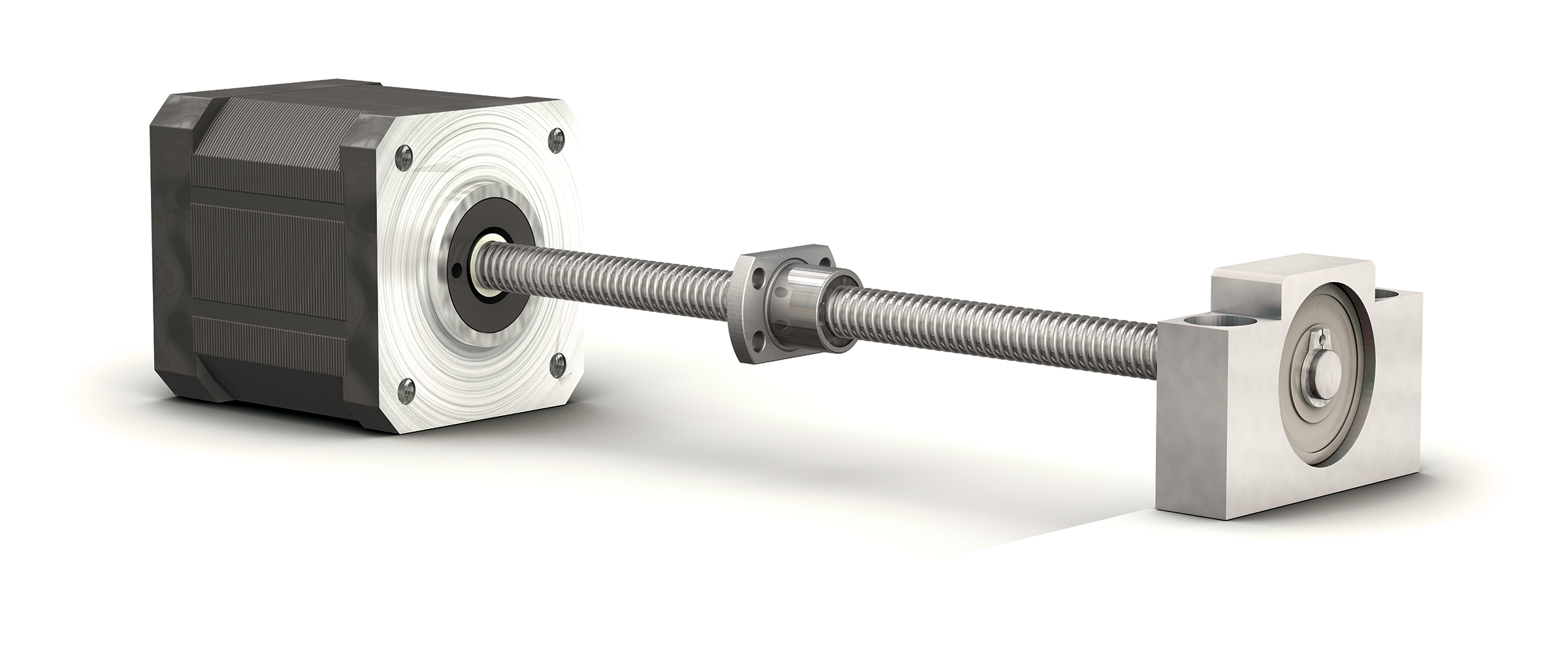
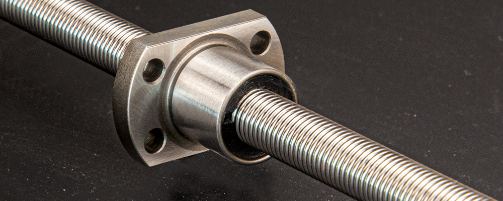
Ball Screw Assemblies
Miniature ball screw assemblies from PBC Linear have a range of leads with small
screw diameters for high precision linear motion. Our ball screws are precision
rolled to achieve lead accuracy and consistency over the full length of the screw,
making them a critical asset to laboratory machines, medical devices, and
mechatronic applications.
Ball screws from PBC Linear are manufactured in
America, avoiding the long lead times associated with overseas shipping.
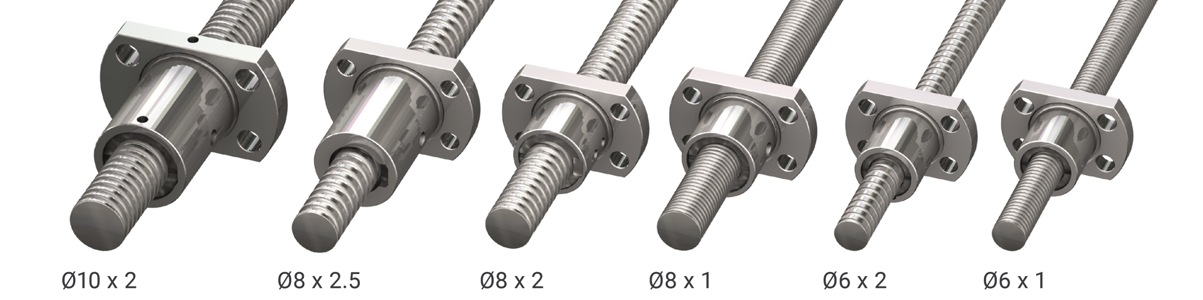
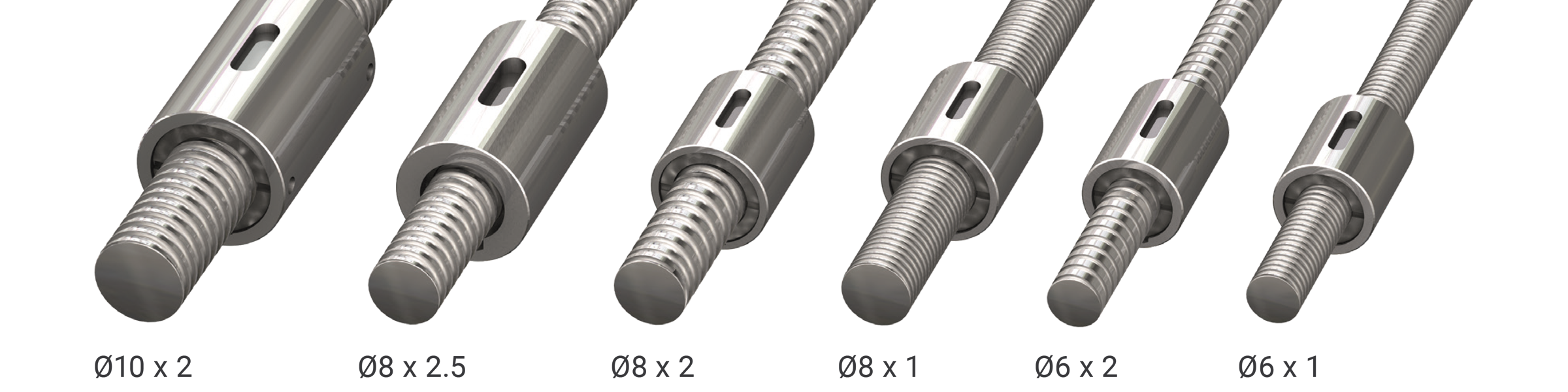
Available Sizes
- 6 metric sizes, measured in diameters x leads:
- 6 x 1
- 6 x 2
- 8 x 1
- 8 x 2
- 8 x 2.5
- 10 x 2
- Standard and special machined journals available
- End support blocks and bearings available
- Grade 5, 7, or 10 accuracy available
Contact an Application Engineer for ordering a specific grade at
application.engineering@pbclinear.com
Compact Nut
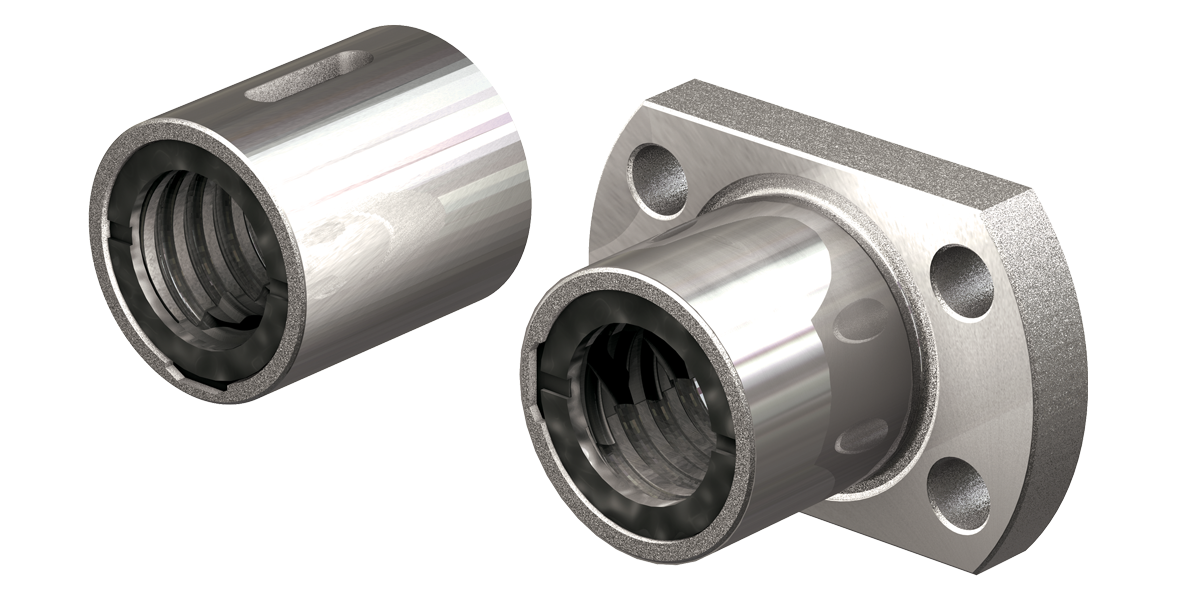
Our compact nut designs utilize internal returns to minimize the nut size and provide quiet motion.
Standard Features:- Flanged and cylindrical nut configurations
- Maximum of 0.05 mm backlash
- High axial load capacities
- Contact PBC Application Engineering about reduced backlash options.
Metrology & Inspection
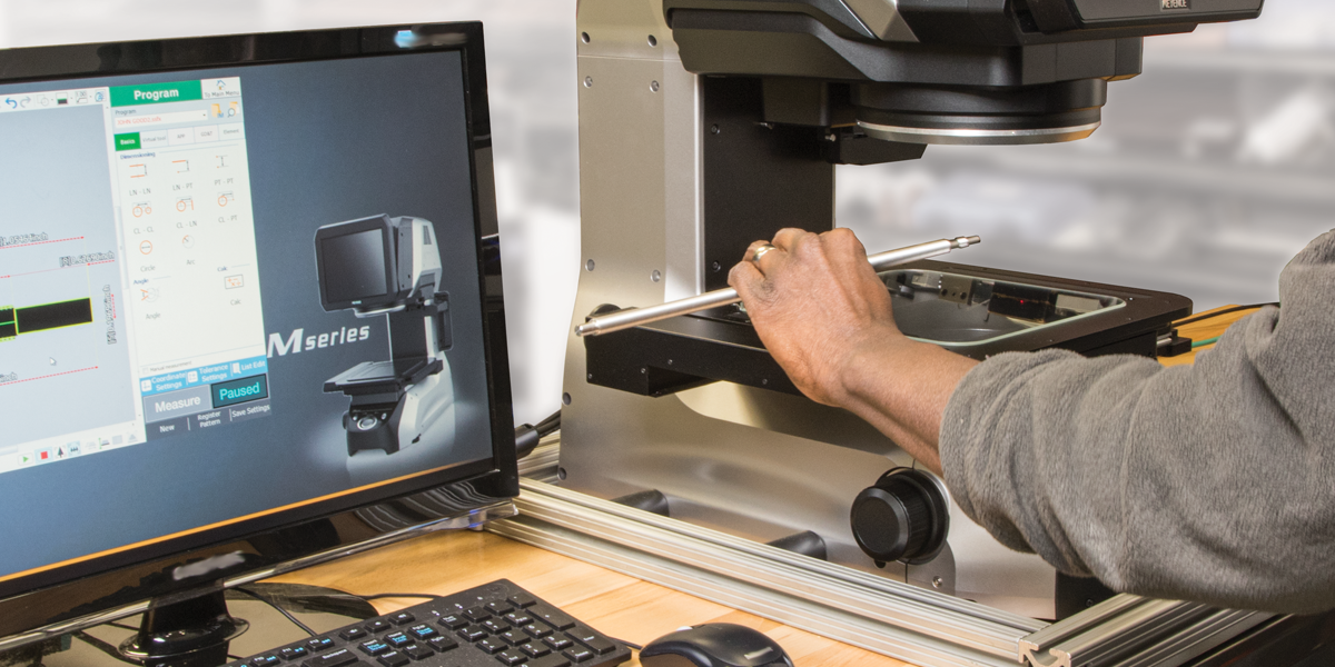
Our commitment to thorough testing is applied to our line of ball screw assemblies.
Metrology devices include:- Keyence optical comparator
- Mitutoyo thread form tracer
- Custom dynamic lead checker
Ball Screw Design Considerations
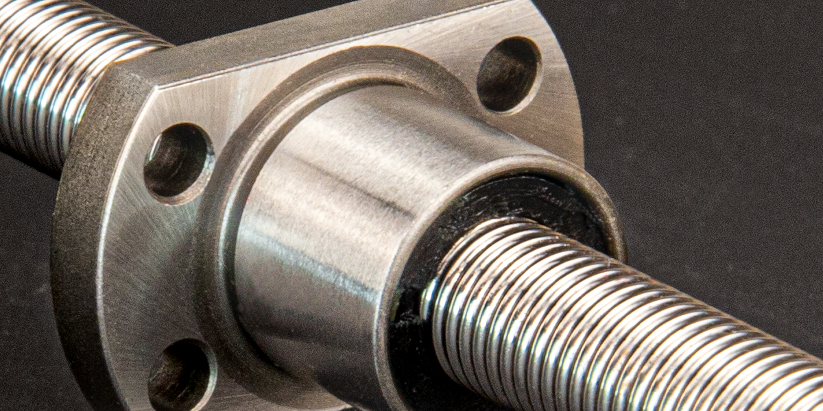
Wipers & Contamination Protection
Wipers are located at each end of the nut to help prevent the ingress of debris and
particulates that could damage the internal balls and affect the ball screw and nut
performance.
The wipers are designed to provide tight clearances that
maximize contamination protection without adding drag or increased friction to the
assembly.
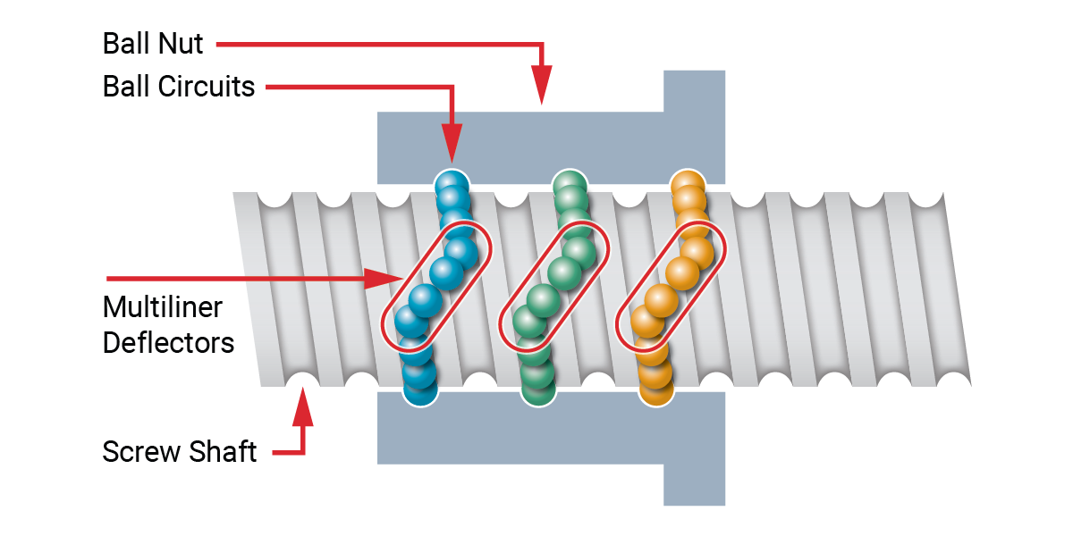
Internal Ball Screw Return System
Ball screw nuts use an internal ball return that guides each turn of balls back to the same threads creating ball circuits within the nuts.
Lubrication
Nuts and screws are shipped with only a light anti-rust protective coating applied.
This anti-rust coating should be removed with a clean solvent wash and then a
lubricant applied that is specific to your application and maintenance
preferences.
Common, general-use lubricants would be a lithium based NLGI 2
grease with an EP additive (Example: Mobil Mobilux EP 2) or an oil such as Mobil DTE
heavy medium oil.
Miniature Ball Screw Applications

Defense
Ball screws meet the required precision and accuracy for various controls and guidance systems. Light weight and compact, ball screws are ideal for tight spaces and provide predictable reliability in critical applications.
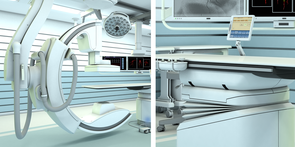
Medical
High load capacity in a small footprint (load density) is a requirement for many medical applications. Ball screws are ideal for medical applications where clean, quiet and smooth operation is critical.

Lab Automation
Testing and automation equipment requires high performance components capable of accurate and repeatable positioning.
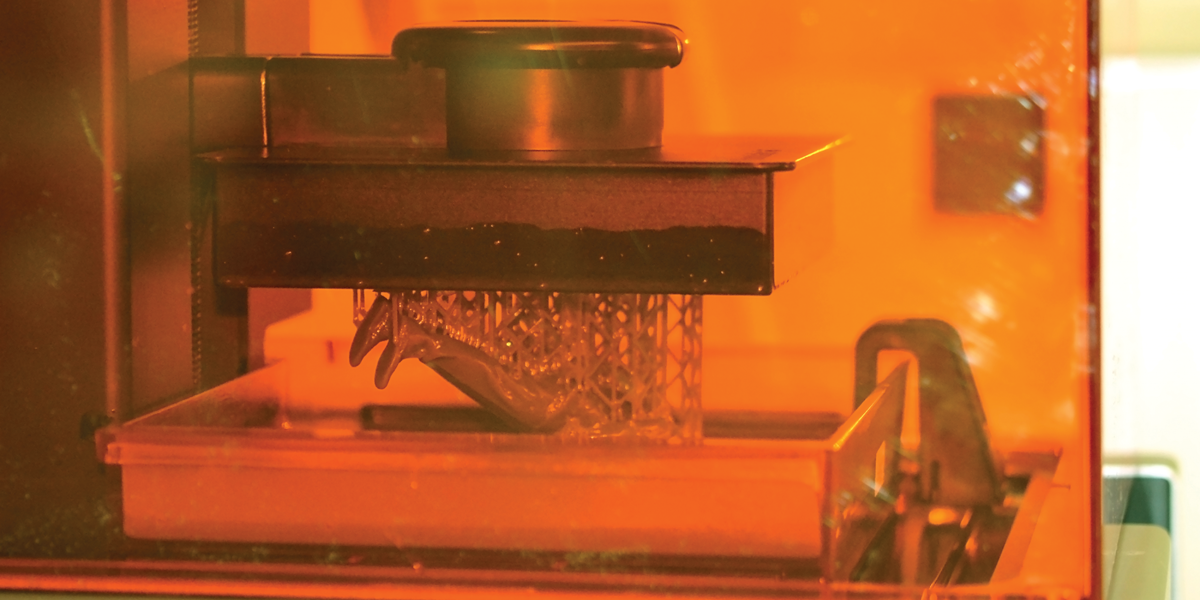
3D Printing
Premium 3D printing equipment requires high accuracy ball screw assemblies built with minimal backlash to produce repeatable quality parts.
American Made
USA Made & Tested
Our ball screw production process offers shorter lead times, avoiding costly downtimes and delays getting to market! Standard ball screws and nuts ship assembled together, but can be ordered separately.
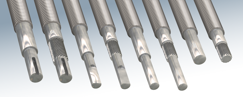
Machined End Customization
Contact PBC Linear about custom machining options available at sales@pbclinear.com or call +1.815.389.5600.
Solutions to Fit Your Application
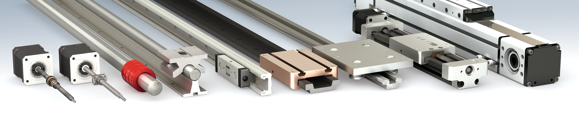
| Lead Screw | Ball Screw | Simplicity Bearings |
Roller Pillow Block |
Cam Roller | Glide Surface | Integral-V | Mechatronics Systems |
|
|---|---|---|---|---|---|---|---|---|
| Inexpensive | ● | ● | ● | ● | ● | ● | ● | ● |
| Low Maintenance | ● | ● | ● | ● | ● | ● | ||
| Compact Size | ● | ● | ● | ● | ||||
| Low Noise | ● | ● | ● | |||||
| Multiple Configurations | ● | ● | ● | ● | ● | ● | ● | ● |
| Washdown Applications | ● | ● | ● | ● | ||||
| Custom Design Support | ● | ● | ● | ● | ● | ● | ● | ● |
| Moderate to High Speed | ● | ● | ● | ● | ● | ● | ● | ● |
| Vacuum & Cleanroom Applications | ● | ●** | ● | ● | ● | |||
| Food Processing | ● | ●** | ● | ● | ● | |||
| Ease of Installation | ● | ● | ● | ● | ● |
** Only with special lubricants
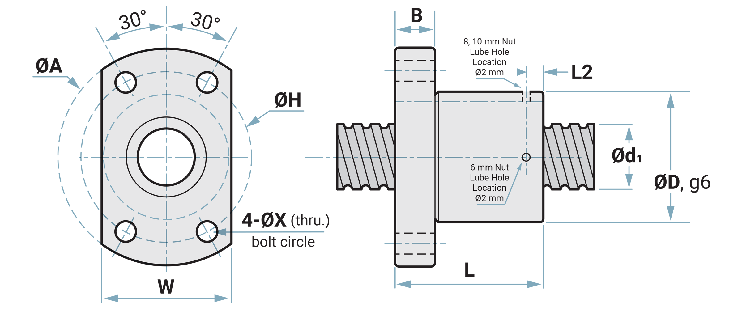
Flange Ball Screws and Nut Sets
| Dia. x Lead mm |
ØD mm |
ØA mm |
B mm |
L mm |
L2 mm |
ØH mm |
W mm |
ØX mm |
|---|---|---|---|---|---|---|---|---|
| 6 x 1 | 12 | 24 | 3.5 | 15 | 2.4 | 18 | 16 | 3.4 |
| 6 x 2 | 12 | 24 | 4.0 | 17 | 2.4 | 18 | 16 | 3.4 |
| 8 x 1 | 14 | 27 | 4.0 | 16 | 3.2 | 21 | 18 | 3.4 |
| 8 x 2 | 14 | 27 | 4.0 | 16 | 2.1 | 21 | 18 | 3.4 |
| 8 x 2.5 | 16 | 29 | 4.0 | 26 | 4.8 | 23 | 20 | 3.4 |
| 10 x 2 | 18 | 35 | 5.0 | 28 | 5.3 | 27 | 22 | 4.5 |
| Dia. x Lead mm |
Static Coa(kN) |
Dynamic Ca(kN) |
|---|---|---|
| 6 x 1 | 0.97 | 0.74 |
| 6 x 2 | 1.14 | 1.05 |
| 8 x 1 | 1.34 | 0.90 |
| 8 x 2 | 1.70 | 1.32 |
| 8 x 2.5 | 1.70 | 1.32 |
| 10 x 2 | 2.18 | 1.49 |
| Dia. x Lead mm |
Screw OD d1 (mm) |
Screw Root Ø d2 (mm) |
Lead Ph (mm) |
Ball Diameter Dw (mm) |
Starts x Circuits |
|---|---|---|---|---|---|
| 6 x 1 | 5.95 | 5.37 | 1 | 0.8 | 1 x 3 |
| 6 x 2 | 5.95 | 5.13 | 2 | 1.2 | 1 x 3 |
| 8 x 1 | 7.95 | 7.29 | 1 | 0.8 | 1 x 4 |
| 8 x 2 | 7.95 | 7.08 | 2 | 1.2 | 1 x 3 |
| 8 x 2.5 | 7.95 | 7.07 | 2.5 | 1.2 | 1 x 3 |
| 10 x 2 | 9.95 | 9.09 | 2 | 1.2 | 1 x 3 |
The static and dynamic load ratings of PBC Linear balls crews were determined by
the ISO 3408 standard calculations.
The dynamic load rating, Ca,
is the load at which 90% of properly lubricated identical ball screws will reach
1 x 10⁶ revolutions.
The static load rating, Coa,
is an axial static load which will produce a permanent deformation at contact
points of the steel balls to ball grooves equal to 0.01% of the ball diameter.
Cylindrical Ball Screws and Nut Sets
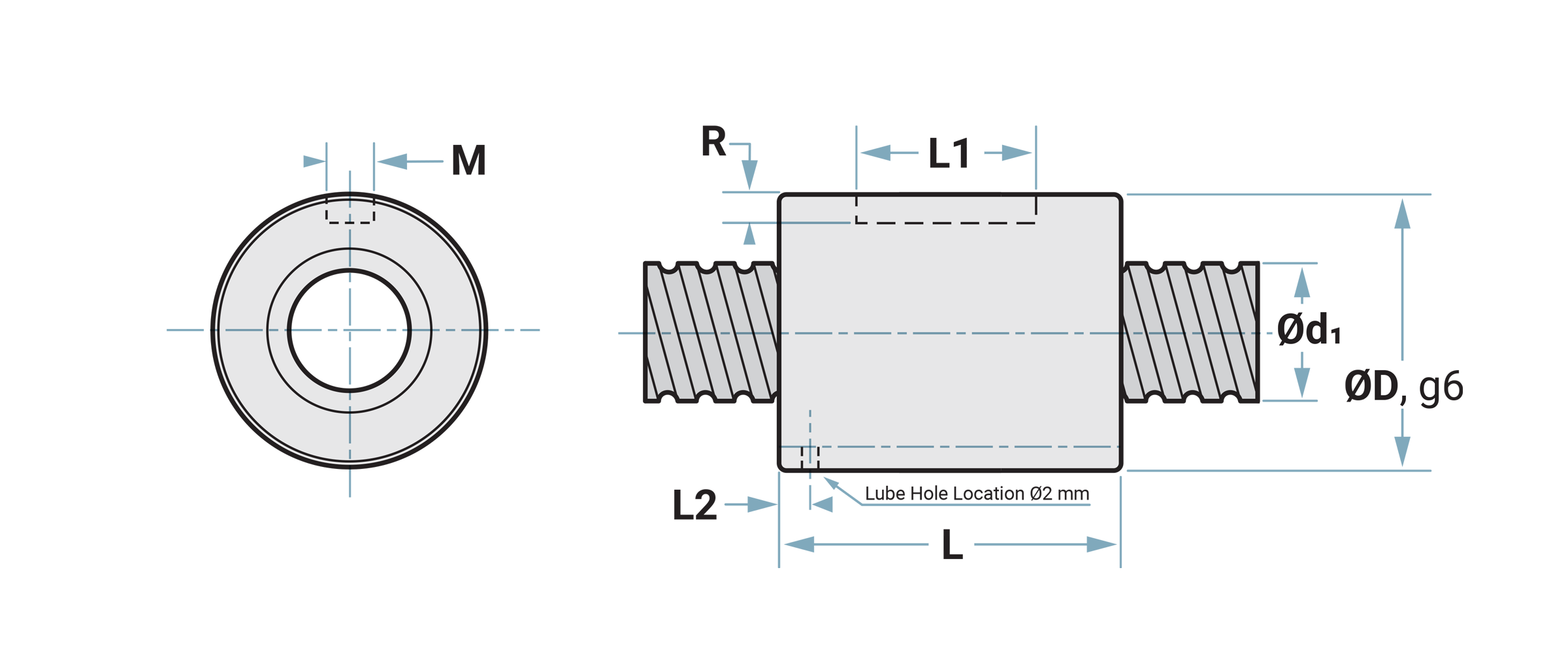
| Dia. x Lead mm |
ØD mm |
L mm |
L1 mm |
L2 mm |
M x R (P9) mm |
|---|---|---|---|---|---|
| 6 x 1 | 12 | 15 | 8 | 2.4 | 2 x 1.2 |
| 6 x 2 | 12 | 17 | 8 | 2.4 | 2 x 1.2 |
| 8 x 1 | 14 | 16 | 8 | 3.4 | 2 x 1.2 |
| 8 x 2 | 14 | 16 | 8 | 2.1 | 2 x 1.2 |
| 8 x 2.5 | 16 | 26 | 10 | 4.8 | 3 x 2 |
| 10 x 2 | 18 | 28 | 10 | 5.3 | 3 x 1.2 |
| Dia. x Lead mm |
Static Coa(kN) |
Dynamic Ca(kN) |
|---|---|---|
| 6 x 1 | 0.97 | 0.74 |
| 6 x 2 | 1.14 | 1.05 |
| 8 x 1 | 1.34 | 0.90 |
| 8 x 2 | 1.70 | 1.32 |
| 8 x 2.5 | 1.70 | 1.32 |
| 10 x 2 | 2.18 | 1.49 |
| Dia. x Lead mm |
Screw OD d1 (mm) |
Screw Root Ø d2 (mm) |
Lead Ph (mm) |
Ball Diameter Dw (mm) |
Starts x Circuits |
|---|---|---|---|---|---|
| 6 x 1 | 5.95 | 5.37 | 1 | 0.8 | 1 x 3 |
| 6 x 2 | 5.95 | 5.13 | 2 | 1.2 | 1 x 3 |
| 8 x 1 | 7.95 | 7.29 | 1 | 0.8 | 1 x 4 |
| 8 x 2 | 7.95 | 7.08 | 2 | 1.2 | 1 x 3 |
| 8 x 2.5 | 7.95 | 7.07 | 2.5 | 1.2 | 1 x 3 |
| 10 x 2 | 9.95 | 9.09 | 2 | 1.2 | 1 x 3 |
The static and dynamic load ratings of PBC Linear balls crews were determined by
the ISO 3408 standard calculations.
The dynamic load rating, Ca,
is the load at which 90% of properly lubricated identical ball screws will reach
1 x 10⁶ revolutions.
The static load rating, Coa,
is an axial static load which will produce a permanent deformation at contact
points of the steel balls to ball grooves equal to 0.01% of the ball diameter.
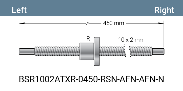
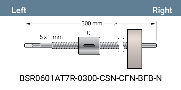
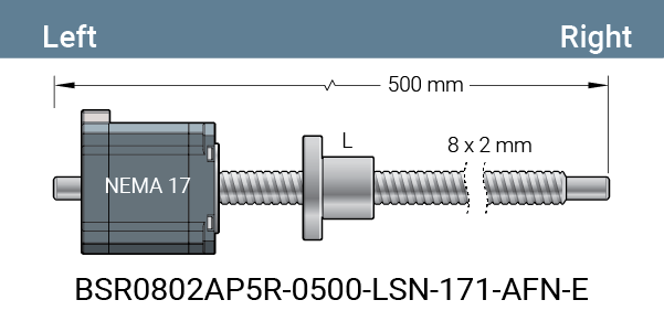
Part Number Configurator
| Type | Thread Dir. |
Diameter and Lead |
Accuracy Class |
Screw Type |
Screw Length | Nut | Backlash | Not Used | Left End | Right End | Special | ||||||||||||||||||||||||||||||||||||||||||||||||||||||||||||||||||||||||||||||||||||||||||||||||||||||||||||||||||
| BS | R | 00000 | TS | RU | - | 0000 | - | L | - | S | - | N | - | 000 | - | AFA | - | E | |||||||||||||||||||||||||||||||||||||||||||||||||||||||||||||||||||||||||||||||||||||||||||||||||||||||||||
TypeBS - Ball Screw Thread DirectionR - Right Diameter and LeadLead is the axial distance the nut advances in one revolution of the screw. The lead is equal to the pitch times the number of starts. Pitch • starts = lead
Accuracy Class*TX - Grade 10, Transport T7 - Grade 7, Transport T5 - Grade 5, Transport P5 - Grade 5, Positioning *Reference ISO 3408-3 for more details about ball screw grades Screw TypeRU - Rolled Screw Length0000 - 4 Digits: Metric Type of NutL - Flanged on Left R - Flanged on Right C - Cylindrical BacklashS - Standard (0.05 mm max) UnusedN - Not used Left End Journal
Note: Floating option bearing blocks not available for 6 mm ball screws Standard Ball Screw assemblies come assembled. Also available as unassembled. Journal tolerances correspond to the ball screw grade accuracy. Contact an Application Engineer for special journals Right End Journal
Note: Floating option bearing blocks not available for 6 mm ball screws Standard Ball Screw assemblies come assembled. Also available as unassembled. Journal tolerances correspond to the ball screw grade accuracy. Contact an Application Engineer for special journals SpecialE - Encoder Ready N - No Option |
|||||||||||||||||||||||||||||||||||||||||||||||||||||||||||||||||||||||||||||||||||||||||||||||||||||||||||||||||||||||||||||
Machined Ends for Bearing Blocks
Fixed Journal Ends
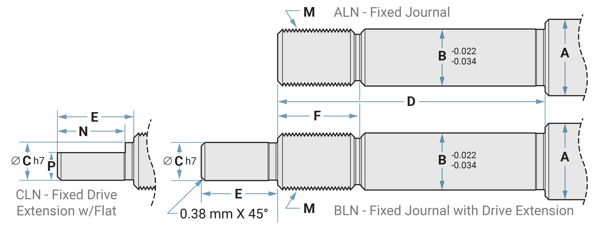
End Block |
A mm |
B mm |
C mm |
D mm |
E mm |
F mm |
M |
N mm |
P mm |
|---|---|---|---|---|---|---|---|---|---|
| EK05 FK05 | 6 | 5 | 4 | 23 | 6 | 7 | M5 x 0.50-6g | 5 | 3.5 |
| EK06 FK06 | 8 | 6 | 4 | 28 | 8 | 8 | M6 x 0.75-6g | 7 | 3.5 |
| EK08 FK08 | 10 | 8 | 6 | 32 | 9 | 10 | M8 x 1.00-6g | 8 | 5.5 |
Floating Journal Ends
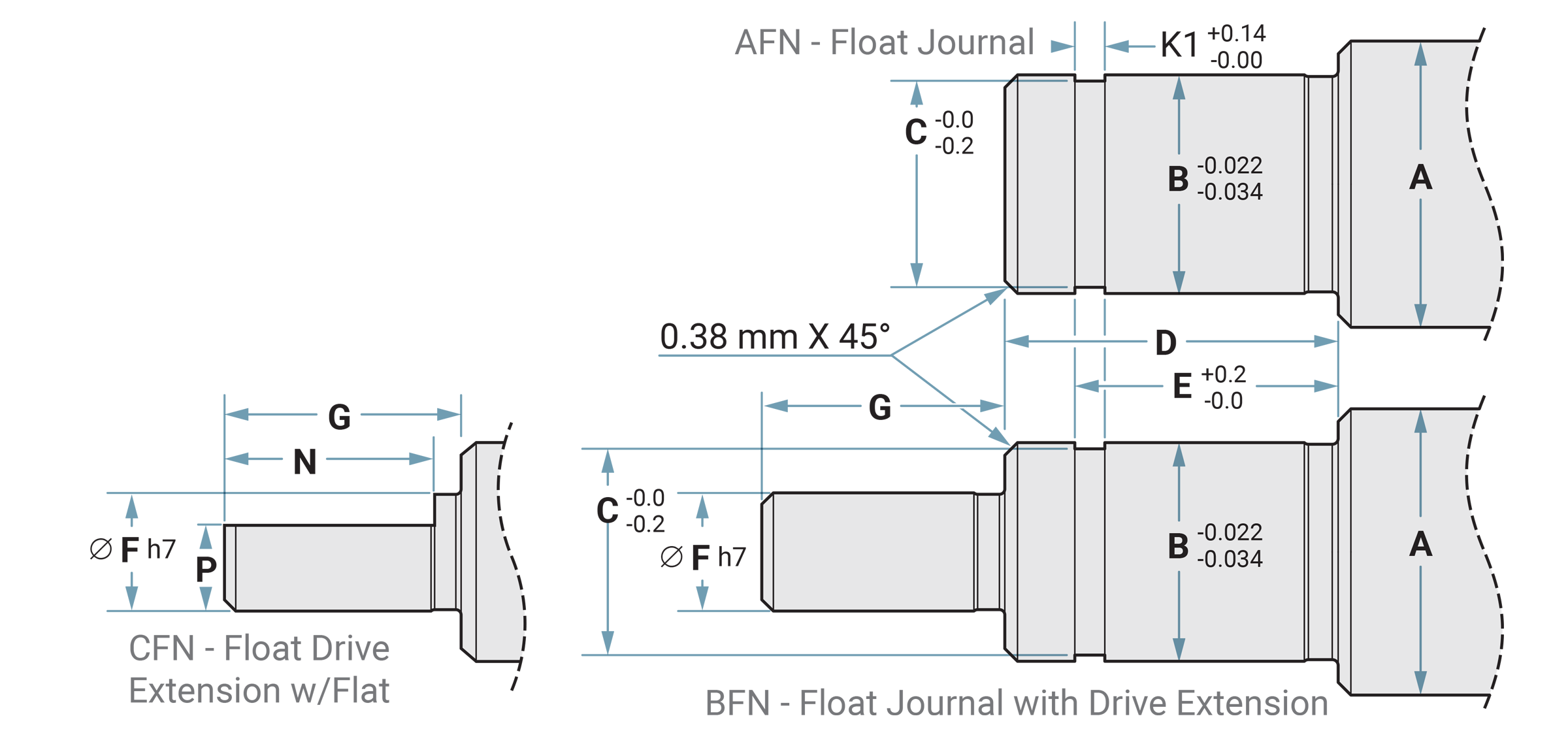
End Block |
A mm |
B mm |
C mm |
D mm |
E mm |
K1 mm |
F mm |
G mm |
N mm |
P mm |
|---|---|---|---|---|---|---|---|---|---|---|
| EF06* EF08 FF06 | 8 | 6 | 5.7 | 9 | 6.8 | 0.8 | 4 | 8 | 7 | 3.5 |
| EF10 FF10 | 10 | 8 | 7.6 | 10 | 7.9 | 0.9 | 6 | 9 | 9 | 5.5 |
*Optional smaller size end block option, see page 11 for sizing of EF06. Must specify EF06 over standard EF08 end block if choosen.
Fixed Bearing Blocks
EK Base Mount Fixed Bearing Blocks
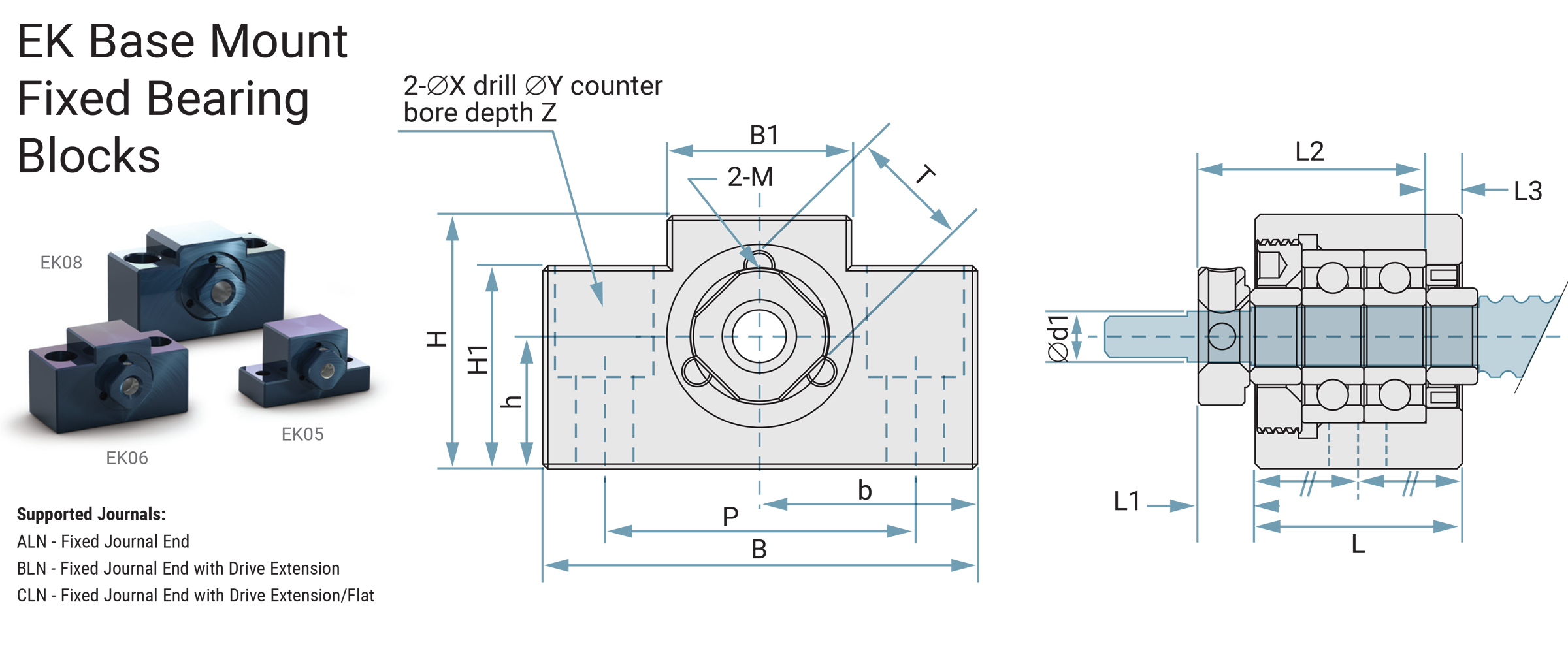
Model # / Part # |
d1 Jour Ø |
L mm |
L1 mm |
L2 mm |
L3 mm |
B ±0.02 |
H ±0.02 |
b mm |
h mm |
B1 mm |
H1 mm |
P mm |
X mm |
Y mm |
Z mm |
M mm |
T mm |
Weight Kg |
|---|---|---|---|---|---|---|---|---|---|---|---|---|---|---|---|---|---|---|
| BSBLEB-05MMP / EK05 | 5 | 16.5 | 5.5 | 18.5 | 3.5 | 36 | 21 | 18 | 11 | 20 | 8 | 28 | 4.5 | - | - | M3 | 11 | 0.1 |
| BSBLEB-06MMP / EK06 | 6 | 20 | 5.5 | 22 | 3.5 | 42 | 25 | 21 | 13 | 18 | 20 | 30 | 5.5 | 9.5 | 11 | M3 | 12 | 0.15 |
| BSBLEB-08MMP / EK08 | 8 | 23 | 7 | 26 | 4 | 52 | 32 | 26 | 17 | 25 | 26 | 38 | 6.6 | 11 | 12 | M3 | 14 | 0.26 |
FK Axial Mount Fixed Bearing Blocks
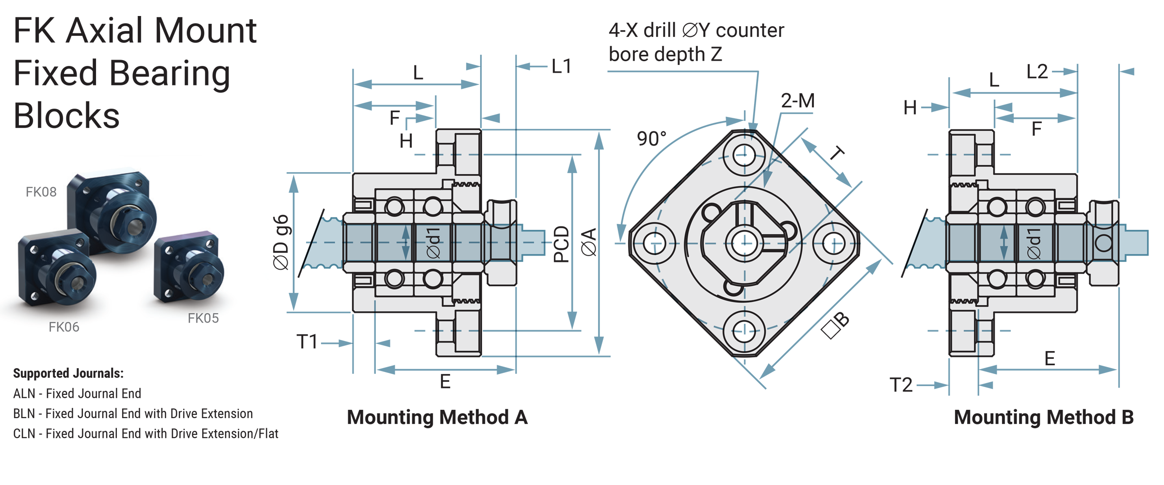
Model # / Part # |
d1 Jour Ø |
L mm |
H mm |
E mm |
Dg6 |
A mm |
PCD mm |
B mm |
L1 mm |
T1 mm |
L2 mm |
T2 mm |
X mm |
Y mm |
Z mm |
M mm |
T mm |
Weight Kg |
|---|---|---|---|---|---|---|---|---|---|---|---|---|---|---|---|---|---|---|
| BSALEB-05MMP / FK05 | 5 | 16.5 | 6 | 18.5 | 20 | 34 | 26 | 26 | 5.5 | 3.5 | 5 | 3 | 3.4 | 6.5 | 3.5 | M3 | 11 | 0.08 |
| BSALEB-06MMP / FK06 | 6 | 20 | 7 | 22 | 22 | 36 | 28 | 26 | 5.5 | 3.5 | 6.5 | 4.5 | 3.4 | 6.5 | 4 | M3 | 12 | 0.1 |
| BSALEB-08MMP / FK08 | 8 | 23 | 9 | 26 | 28 | 43 | 35 | 35 | 7 | 4 | 8 | 5 | 3.4 | 6.5 | 4 | M3 | 14 | 0.15 |
Floating Bearing Blocks
EF Base Mount Floating Bearing Blocks
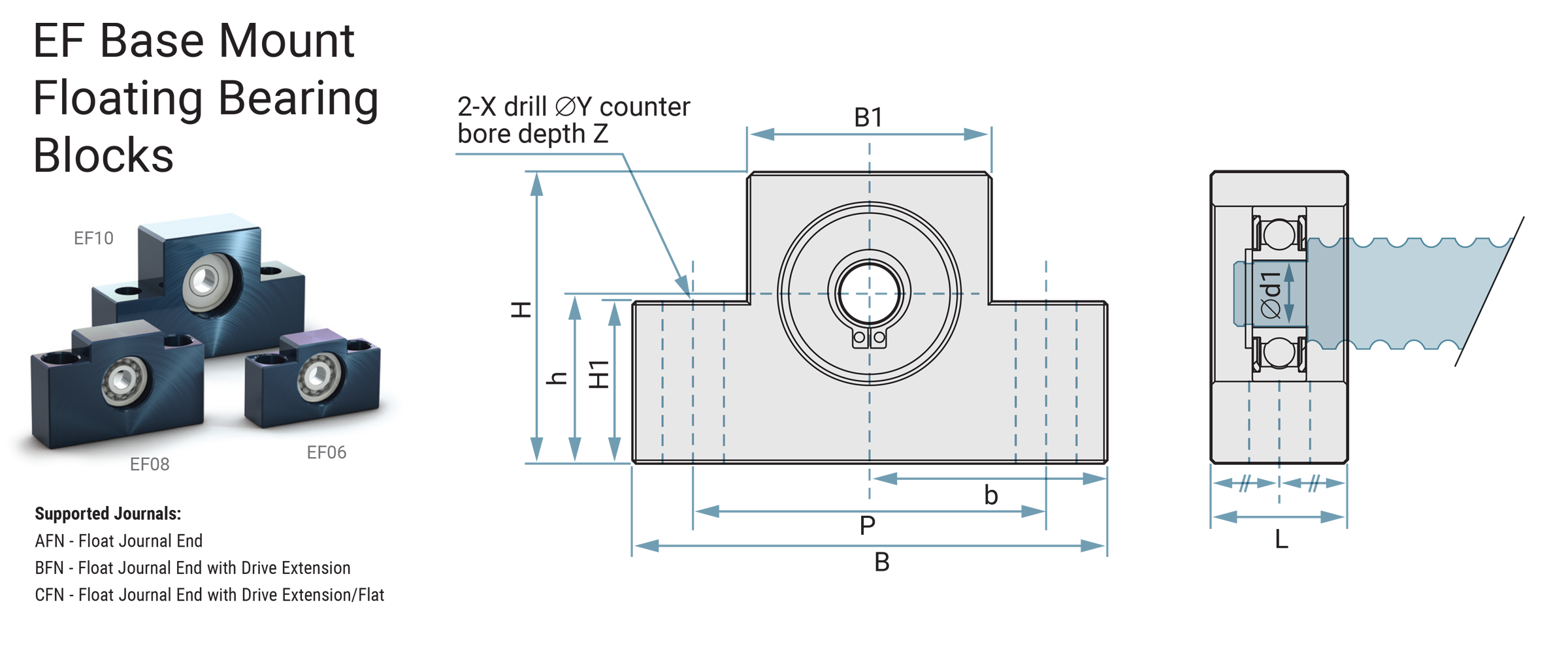
| Model # / Part # |
d1 Jour Ø |
L mm |
B mm |
H mm |
b ±0.02 |
h ±0.02 |
B1 mm |
H1 mm |
P mm |
X mm |
Y mm |
Z mm |
Bearing |
Snap Ring |
Weight Kg |
|---|---|---|---|---|---|---|---|---|---|---|---|---|---|---|---|
| BSBFEB-06MMP / EF06 | 6 | 12 | 42 | 25 | 21 | 13 | 18 | 20 | 30 | 5.5 | 9.5 | 11 | 606ZZ | S 06 | 0.1 |
| BSBFEB-08MMP / EF08 | 6 | 14 | 52 | 32 | 26 | 17 | 25 | 26 | 38 | 6.6 | 11 | 12 | 606ZZ | S 06 | 0.15 |
| BSBFEB-10MMP / EF10 | 8 | 20 | 70 | 43 | 36 | 25 | 36 | 24 | 52 | 9 | - | - | 608ZZ | S 08 | 0.33 |
FF Axial Mount Floating Bearing Blocks
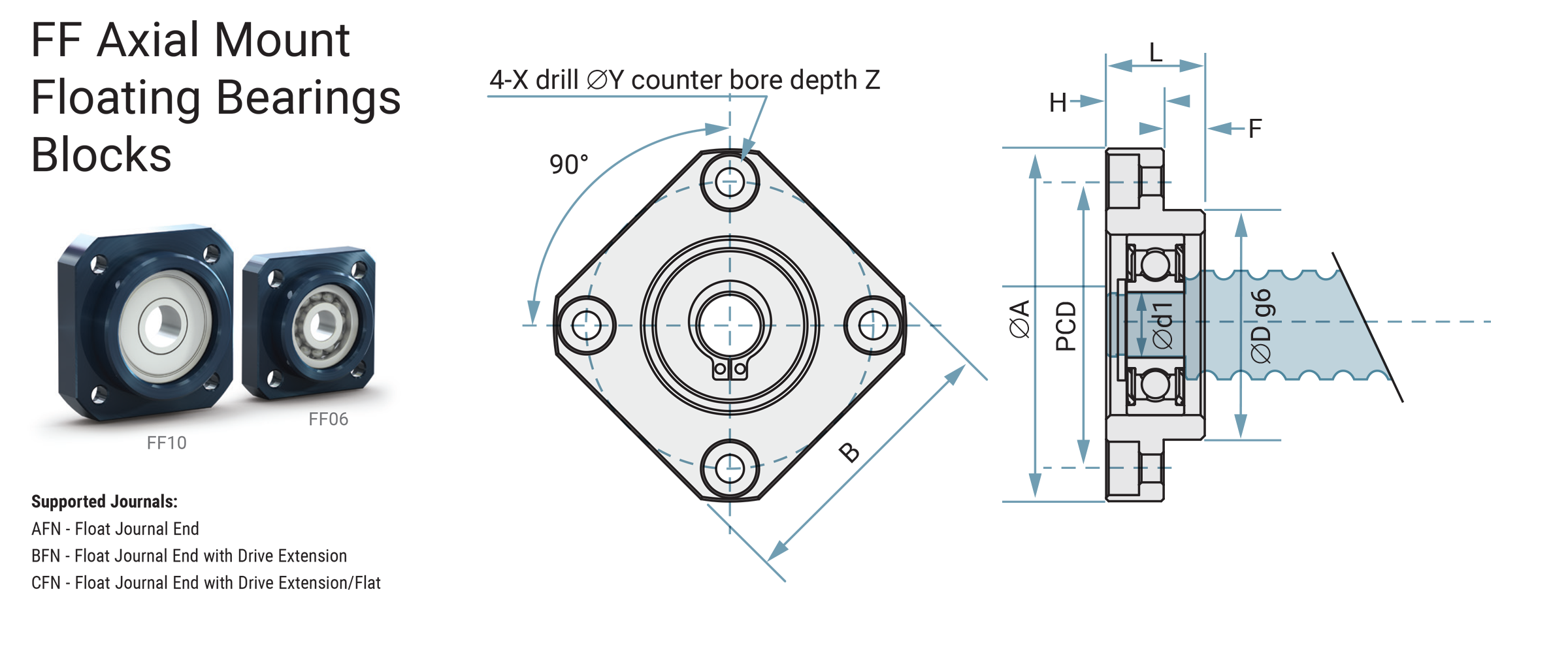
| Model # / Part # |
d1 Jour Ø |
L mm |
H mm |
F mm |
Dg6 |
A mm |
PCD mm |
B mm |
X mm |
Y mm |
Z mm |
Bearing |
Snap Ring |
Weight Kg |
|---|---|---|---|---|---|---|---|---|---|---|---|---|---|---|
| BSAFEB-06MMP / FF06 | 6 | 10 | 6 | 4 | 22 | 36 | 28 | 28 | 3.4 | 6.5 | 3.5 | 606ZZ | S 06 | 0.06 |
| BSAFEB-10MMP / FF10 | 8 | 12 | 7 | 5 | 28 | 43 | 35 | 35 | 3.4 | 6.5 | 4 | 608ZZ | S 08 | 0.1 |
Technical • Max Speed Calculations
Calculating the Maximum Speed of a Ball Screw System
The maximum speed possible for a ball screw assembly depends on the ball screw diameter, the unsupported length of the ball screw, how the ball screw is supported, the type of lubrication system (oil or grease), and the construction of the ball return system in the ball nut.
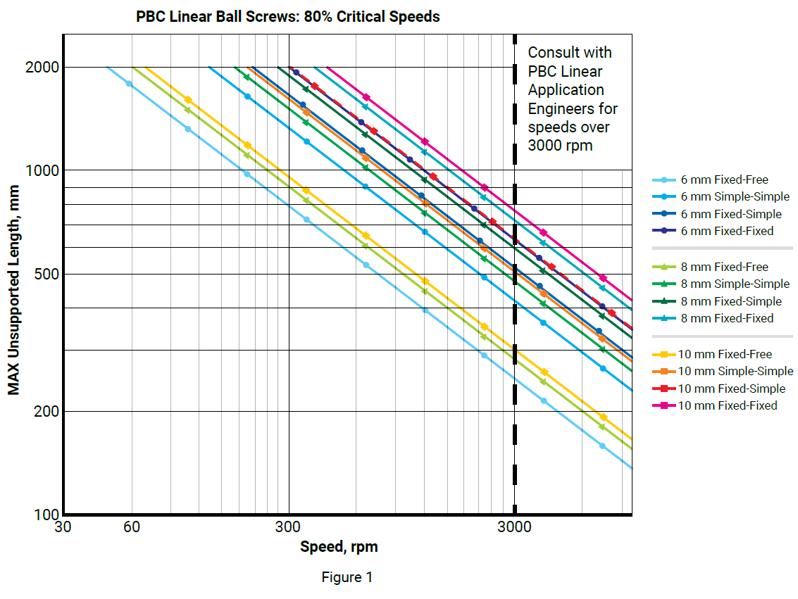
I. Critical Speed of the Ball Screw
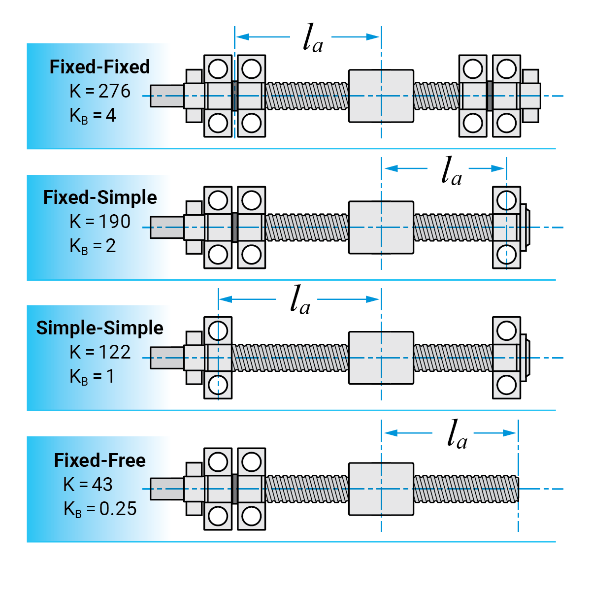
The critical speed of a ball screw is its first natural frequency. PBC Linear recommends operating below 80% of the ball screw’s critical speed. The critical speed of a ball screw is dependent on its root diameter, its unsupported length, and how its ends are supported. Fig. 1 shows the 80% critical speed values for PBC ball screws corresponding to the formula below.
\( \large\boldsymbol{n_{\text{max}} = K \cdot 10^6 \cdot \frac{d_2}{l_a^2} \cdot S.F.} \)
\( \large\boldsymbol{n_{\text{max}}} \) = maximum rotational speed (rpm)
\(
\large\boldsymbol{K} \) = factor for the type of ball screw supports (see fig.
2)
\( \large\boldsymbol{d_2} \) = screw thread root diameter (mm)
\(
\large\boldsymbol{l_a} \) = maximum unsupported length (mm) (see fig. 2)
\(
\large\boldsymbol{S.F.} \) = safety factor 0.8
II. Maximum Speed of the Ball Return System
The rotational speed characteristic for ball nuts with multiliner ball returns and rolled ball screws. If the ball screw is relatively lightly loaded and it is properly lubricated, the maximum possible speed allowed by the ball return system can be estimated by the formulas below. (Use where \( \small{D_m \cdot N \leq 50,000 } \) )
\( \large\boldsymbol{n_{\text{max}} = \frac{ D_m {\text{ }} \cdot {\text{ }} N}{d_1}} \)
\( \large\boldsymbol{n_{\text{max}}} \) = maximum rotational speed (rpm)
\(
\large\boldsymbol{D_m {\text{ }} \cdot {\text{ }} N} \) =
rotational speed characteristic of the ball return system (rpm • mm)
\(
\large\boldsymbol{d_1} \) = ball screw’s nominal (outside) diameter (mm)
Note: For maximum speeds greater than 3000 rpm, please consult with a PBC Linear Applications Engineer.
III. Maximum Traverse Speed
Once limiting nMAX is found in I (Critical Speed) or II (Maximum Speed), the maximum traverse speed can be calculated using the formula below with the lower nMAX:
\( \large\boldsymbol{V_{\text{max}} = \frac{ n_{\text{max}} \cdot {\text{ }} P_h}{60}} \)
\( \large\boldsymbol{V_{\text{max}}} \) = maximum possible traverse speed
(mm/sec)
\( \large\boldsymbol{P_h} \) = thread lead (mm)
Technical • Max Static Load Calculations
Calculating the Maximum Static Loading of a Ball Screw System
I. The maximum permissible static load, Fper
\( \large\boldsymbol{F_{\text{per}} = \frac{ C_{\text{0a}}}{f_s}} \)
\( \large\boldsymbol{F_{\text{per}}} \) = maximum permissible static load derated
for application conditions (Newtons)
\( \large\boldsymbol{f_s} \) = derate
factor based on application conditions
| Machine Type | (fs) Factor No Vibration or Impacts |
(fs) Factor With Vibration or Impacts |
|---|---|---|
| General Machinery | 1.0 to 2.0 | 2.5 to 7.0 |
| Machine Tools | 1.0 to 1.5 | 2.0 to 3.0 |
II. Permissible buckling force, FB
Ball screws should be loaded in axial compression to levels below their maximum column loading. Exceeding the maximum column loading can result in instability due to screw bending or buckling.
\( \large\boldsymbol{F_B = \frac{K_b {\text{ }} \cdot {\text{ }} d_2^4}{S_B {\text{ }} \cdot {\text{ }} l_a^4} \cdot 10^5} \)
\( \large\boldsymbol{K_B} \) = factor for end support designs (see fig.2)
\(
\large\boldsymbol{d_2} \) = thread root diameter of the ball screw (mm)
\(
\large\boldsymbol{S_B} \) = factor of safety for buckling. Normally 2 to 4
\(
\large\boldsymbol{l_a} \) = maximum screw length acted upon by axial force (mm)
Technical • Life Calculation
Calculating the Nominal Service Life L10 or Lh
The formula to calculate the service life that 90% of identical, properly lubricated ball screws are expected to reach is given below:
\( \large\boldsymbol{L_{\text{10}} = (\frac{ C_a}{F_m})^3 \cdot 10^6} \)
\( \large\boldsymbol{L_{\text{10}}} \) = service life (revolutions)
\(
\large\boldsymbol{C_a} \) = dynamic load rating (N)
\( \large\boldsymbol{F_m}
\) = average axial load (N)
\( \large\boldsymbol{L_h = \frac{ L_{\text{10}}}{n_m {\text{ }} \cdot {\text{ }} 60}} \)
\( \large\boldsymbol{L_h} \) = service life (hours)
\( \large\boldsymbol{n_m}
\) = average rotational speed (rpm)
In applications where vibration or impact loading is present, or if the application speed is very high, then the nominal life calculations can be adjusted as follows:
\( \large\boldsymbol{L_{\text{10}} = (\frac{ C_a}{f_w {\text{ }} \cdot {\text{ }} F_m})^3 \cdot 10^6} \)
| Vibration or Impact | Load Drate Factor (fw) |
|---|---|
| Minor | 1.0 to 1.2 |
| Low | 1.2 to 1.5 |
| Moderate | 1.5 to 2.0 |
| High | 2.0 to 3.5 |
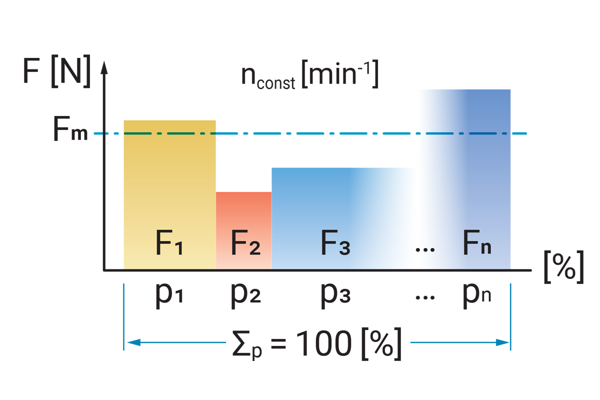
I. Average axial load \( F_m \) for constant rotational speed and varying axial load
\( \large\boldsymbol{F_m = \sqrt[3]{F_1^3 \cdot \frac{P_1}{100} \text{ + } F_2^3 \cdot \frac{P_2}{100} \text{ +} \text{ ... } \text{+ } F_n^3 \cdot \frac{P_n}{100}}} \)
\( \large\boldsymbol{F_{\text{1,2,...,n}}} \) = load per cycle unit (N)
\(
\large\boldsymbol{P_{\text{1,2,...,n}}} \) = cycles (%)
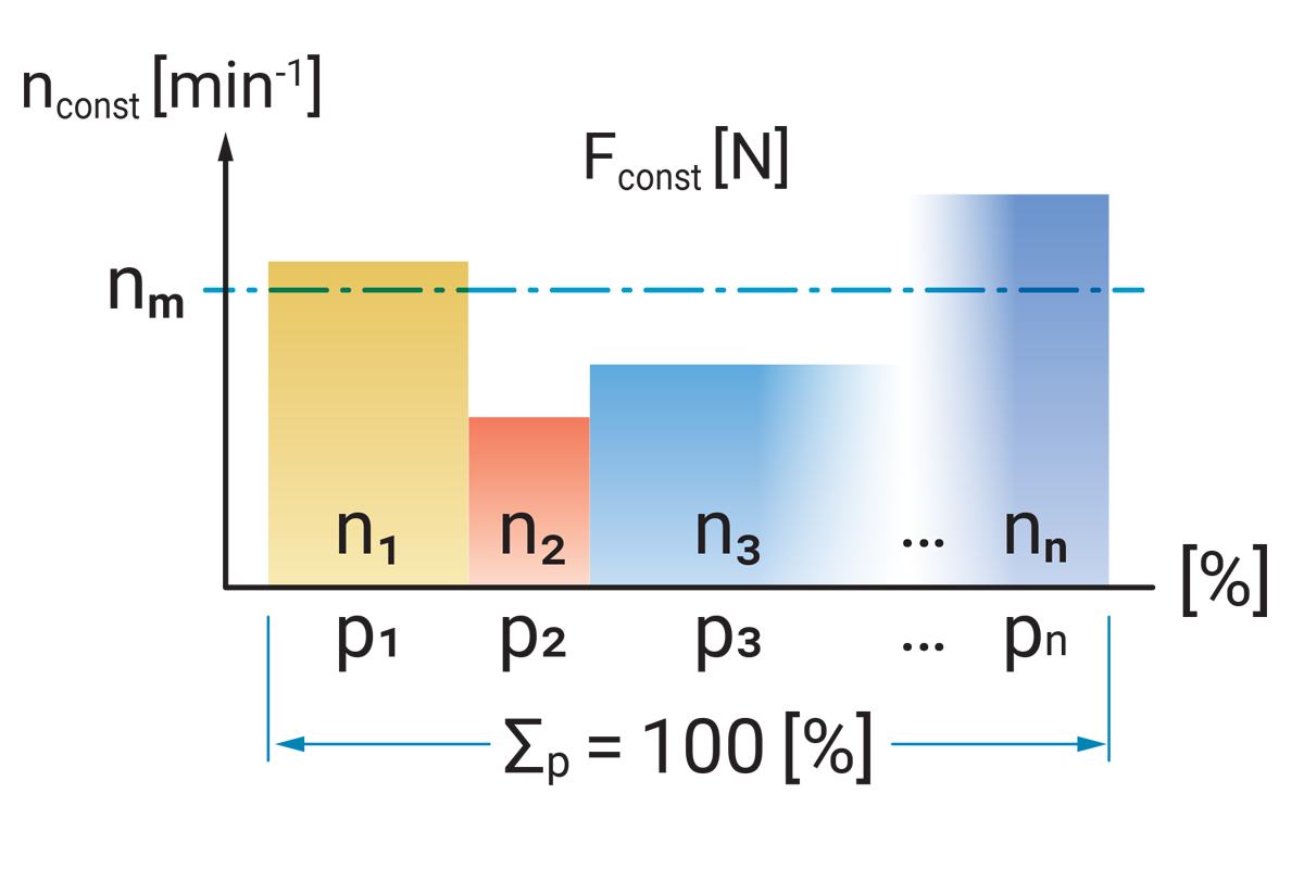
II. Average rotational speed at constant axial load \( F_{\text{const}} \) and variable rotational speed
\( \large\boldsymbol{n_m =n_1 \cdot \frac{P_1}{100} \text{ + } n_2 \cdot \frac{P_2}{100} \text{ +} \text{ ... } \text{+ } n_n \cdot \frac{P_n}{100}} \)
\( \large\boldsymbol{n_{\text{1,2,...,n}}} \) = rotational speed per cycle unit
(rpm)
\( \large\boldsymbol{P_{\text{1,2,...,n}}} \) = cycles (%)
Technical • Ball Screw Grading
Positioning or Transport Ball Screws
Ref: ISO 3408-3
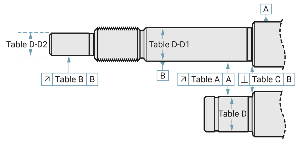
| ISO Reference | Grade 3 μm |
Grade 5 μm |
Grade 7 μm |
Grade 10 μm |
|
|---|---|---|---|---|---|
| Table A | ISO 3408-3 E6.1 | 12 | 20 | 40 | 63 |
| Table B | ISO 3408-3 E7.2 | 8 | 10 | - | - |
| Table C | ISO 3408-3 E8.2 | 4 | 5 | - | - |
| Table D | Journal Ø | Ground -8/-15 (h7) |
Ground -8/-15 (h7) |
Turned -22/-34 (h7) |
Turned -22/-34 (h7) |
Positioning or Transport Ball Screws
Ref: ISO 3408-3 E3
Checking of the travel variation V300 within an axial travel of 300 mm:
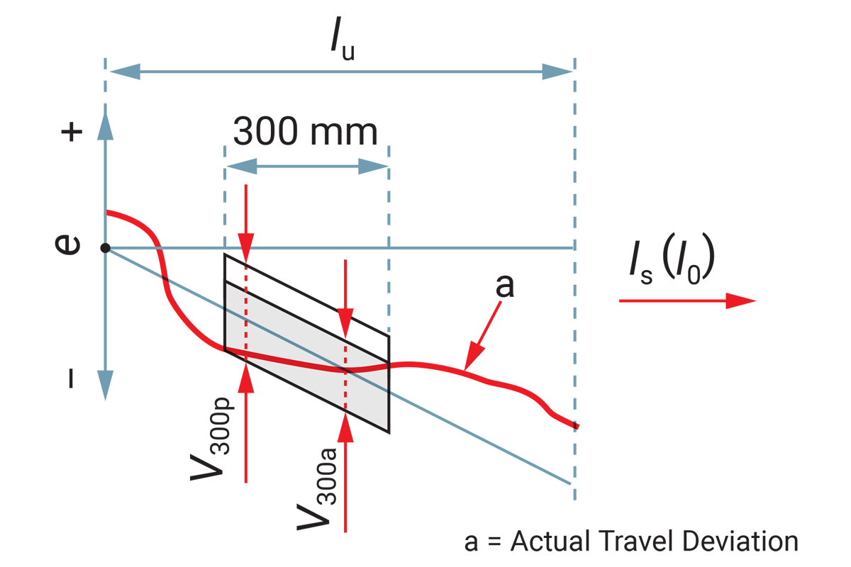
| Standard Tolerance | V300 μm |
|---|---|
| Grade 3 | 12 |
| Grade 5 | 23 |
| Grade 7 | 52a |
| Grade 10 | 210a |
a = Only for transport ball screws
Positioning Ball Screws
Ref: ISO 3408-3 E4
Checking of the travel variation V2πt within 2π rad:
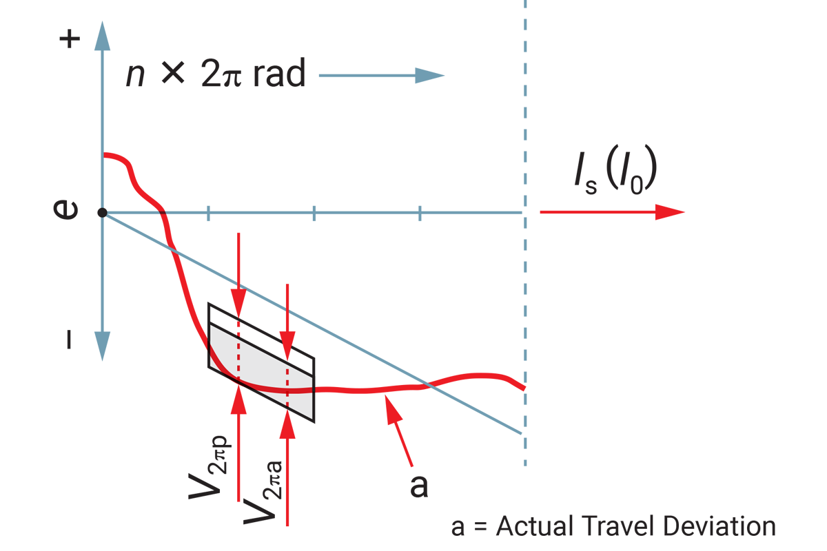
| Standard Tolerance | V2π μm |
|---|---|
| Grade 3 | 6 |
| Grade 5 | 8 |